Towers of Power 1: IMSI, IMEI, Built to Last

Starting in Towers of Power, our initial assignments were to setup an Ubuntu environment in VirtualBox (done!), find our IMSI and IMEI numbers for our phones, and read the first two chapters of “Built to Last” by Jim Collins.


My experience with finding my IMSI and IMEI numbers was interesting. First, Googling what they are. The IMSI is your phone’s International Mobile Subscriber Identity, and the IMEI is the International Mobile Equipment Identity. My understanding is that the IMSI is based around the SIM while the IMEI is based around the device itself.

The IMEI can be found in an Android system by going into the Settings>About Phone>Status>SIM Status. There is also the option to dial the number *#06# in the dialer and then the number pops up.

But I couldn’t find the IMSI. Googling around seemed to indicate that some Android phones have it in the settings, while others don’t. Some people claimed that the number printed on your SIM card was your IMSI and others disagreed. Then in Googling, I saw that there were plenty of Android apps that could tell you your IMSI… but I got paranoid. You aren’t supposed to give that information away, and I was having trouble trusting any of the apps not to harvest my data.

I wound up calling T-Mobile customer support, who informed me that my IMSI is the same as my IMEI. I’m partly skeptical of this answer as being something a customer service rep might say just to get someone off the line, so I’m going to follow up on this with Dhruv and Edwin.


“Built to Last” was interesting, and having us stop at the end of chapter two felt a little bit like a cliffhanger, so I will be coming back to it when I have the time. I’m not necessarily the most business oriented person. And when I am it is more about having an idea for something I would want to make and then perhaps building a business model around it. This isn’t the ethos of “Built to Last”, nor of many of the tech/app economy types we usually get exposed to. But I did come to appreciate what Collins was positing.

I kept thinking of the word “sustainability” and how it has so much more meaning than in an ecological sense. How do you have organizational sustainability? In some of his examples of “clock makers, not time tellers” he talks about the United States and the intentions of the founding fathers to build a system that outlasted any one lifetime. I like this idea in an of itself, but also the realization that this organizational sustainability doesn’t need to be solely business oriented.

If you wish to obtain a more abstract goal, value, or set of beliefs; that often isn’t just about reaching it once and then proclaiming victory. It is a thing that needs to be reproduced and maintained continually. Clock making, not time telling. Teaching to fish instead of giving fish. Seems like a worthwhile art to study. And not only is it practical in that sense, but I appreciated the idea of having these core values be grounding in a way. Nice to think of being able to meditate on a strong and simple belief when navigating hectic terrain.

ICM Final: The Impulse and the Response

For my final project in Intro to Computational Media, I decided to focus on the p5 Sound library’s convolution reverb functionality. Reference for that object can be found here. Technically, I have been interested in p5’s ability to handle sound in the browser. Conceptually, I have been interested in convolution reverb as a medium for artistic messaging. In terms of my broader practice, I was excited to not only produce work in a collaborative manner but also create a tool for artists to use.


The result is a two part final. One, is a piece titled “The Impulse and the Response”. Two, is a browser based tool to be given to artists in order to create more pieces of a similar nature as this one.

“The Impulse and the Response”

This piece consists of two interactive sound pieces to be played in the browser alongside explanatory text. Two artists, Édgar J. Ulloa and Daniela Benitez, provided audio performances. A slider is available to change the amount of reverb that affects the audio that is playing. The reverb is a re-creation of the sonic qualities of the inside of the Statue of Liberty. In collaboration, my prompt to the artists was, “If you could do a sound performance inside of the Statue of Liberty, what would it be?”

Screenshot of “The Impulse and the Response”

Traditionally, convolution reverb is used to easily recreate reverbs of sonically pleasing spaces. Even experimentally, non-traditional use of convolution reverb focuses on innovative sound design results. I was interested in the potential for political or social commentary. Both of my collaborators describe themselves as affected by the United State’s immigration policy, social attitudes towards immigration policy, and the general climate of xenophobia. They wished to make pieces addressing these issues.

Giving them the opportunity to virtually inhabit this symbolic space not only gives potential to critique the space and it’s multi-dimensional symbolism, but uses the act of recreation of the space and it’s virtualization to match the physical, psychological, and political state of flux that many immigrants can face.

Challenges

The artistic metaphor completely relies on the technical understanding of how a convolution reverb works. However, most official definitions of convolution reverb err on the technical side and as a result are not always helpful descriptions to the average person. With this in mind, I decided that a brief but thorough artist’s statement that explains convolution reverb was essential. With that in mind, I will link to the piece here so that you can read about convolution reverb and it’s relevance to the piece in detail.

The Impulse and the Response

First approaches

My initial idea was about the general potential of convolution reverb as an artistic message. I had less thought about the possibilities of recreating spaces, but more of putting audio “through” another sound. Since convolution reverb works by loading other sounds, called impulse responses, to create reverberations, you can put any sound into it for unexpected results. The sound of the arctic shelf cracking and falling into the ocean could be used as an impulse response in a sound piece about global warming, for example.

My first presentation on the idea revolved around police shootings. Loud pops and bangs are used to create traditional impulse responses, and on the professional level may be done with starter pistols. I had mocked up an interface for a piece that would use audio from the shooting of Keith Lamont Scott as the impulse response for a convolution reverb. The user would be prompted to read news articles about the shooting.

The general approach was to use convolution reverb to achieve a kind of empathy that may not be available in other forms of media. Having your voice brought into this “space” created by the reverb may more easily prompt you to think about yourself in that space. After discussion the general concept with Allison Parrish, it was apparent that there was the potential for very problematic usage of this approach. Not only in the procuring of media as appropriation, but the general feeling of a serious and fatal issue boiled down into a “sound toy” that you play with.

Allison’s advice to hold the technology and the message in separate spaces while meditating on potential concepts was invaluable, and lead me to the current incarnation of the project. I feel that what I have is a much more positive approach while still having a strong social message, and is empowering to artists. This revolves around the second part of my project.

Convolution Reverb Online

At the bottom of the piece is a link where you can create similar pieces of your own. The broader vision for this is that I can provide this link to Édgar, Daniela, and other potential collaborators so that they can create their own versions of this kind of piece without having to rely on sound engineers or programmers.

Here is a screenshot of an initial prototype:

In trying to achieve a user friendly user experience, I learned much about Javascript , p5, and browser capabilities in general. This has been very enlightening, and I am very glad I could work on practical Javascript usage in this project. Some decisions while not practical, offered good practice; like trying to program as much of the UI as I could inside of Javascript instead of pre-made HTML. Other learning points were great research; iOS does not allow Javascript access to the microphone. Not just Safari, but iOS as a system. And I wound up writing some code I imagine myself coming back to over and over, like file uploads that can use system menus as well as drag and drop functionality.

Screenshot of Convolution Reverb Online tool

Source Code for Convolution Reverb Online

The Experience

While there are things to revisit on this project in terms of design, layout, and code cleanliness, I am really happy with the results. It has been a while since I tried to use solely Javascript for interactive work, and being able to immerse myself in p5 has been a great re-introduction to what the browser is capable of. And more so, the ethos of p5 was fully felt. I was able to program something novel and expressive without the syntax and technical aspects getting in the way. My classmates’ wonderful feedback, and Allison Parrish’s guidance was so important and appreciated. I’m proud of the end result, and am motivated to continue exploring programming as an artistic skill. It also seems that this project will have a life after this class, which I am very excited about further developing.

PComp: Final Project Update

This past week we had a play testing session with one of the other Physical Computing sections. 

It was good to see people who hadn’t heard of my project before approach it for the first time. Also, it seems that the people with musical performance and production experience almost immediately understood the usage and potential. Very encouraging.

I’ve been a bit obsessed with having a low profile and slick fabrication of the Mic Cuff. The grip and feel of it is as much a functional interface question as it is about the aesthetic appeal. I went out on a limb with an idea, trying to work with bent acrylic.

I had done some measurements and cut a couple rectangles to work with. But I needed to practice on a scrap piece first and see how this might work.

Definitely takes a while to understand the feel of bending acrylic, but I got something functional. And I was pretty happy with the sturdiness.

Moving onto the main piece.

Not too bad. Felt good in the hand. The next step was figuring out how to mount onto the surface effectively. Keep in mind, the inside of the cuff has to be smooth in order to accommodate the mic.

In order to make it as light and as uncluttered as possible, I decided to move the board off of the cuff. Wires will go to a separate controller, which will then plug into the computer via USB.

Moving onto my button mounting concept

I want to use cork as a way to mount the buttons. The protoboard, while providing a space and security for soldering, can also serve as a kind of “slot” system for inserting the buttons. Cork provides a kind of tacticle/ergonomic “landing pad” for fingers and finger tips to grip the mic.

I played around with a few different approaches.

Cracking can potentially be an issue, but I found a solution that so far has felt fairly secure.

Then I further sculpted the cork to create more of a natural grip.

As of right now, I have mounted the pieces with double sided tape. Fairly secure but seems to be remove-able and not irrevocably permanent.

The grip feels good in the hand, and I am actually surprised this works as well as it does. I’ve ordered some terminal blocks off of Adafruit so I can attach the wires to the Teensy without having to permanently attach them (in case I need to trouble shoot) but keeping it sturdy and secure (so I hopefully don’t have to trouble shoot).

Feeling good about the physical progress. I’m going to continue refining the software while I wait for my order to come in.

Intro to Fab 6: Mounting Motors

Our last assignment for class was working with motors: attaching them to things, and attaching things to them. There is a class at ITP called “If it moves, it breaks”, and I certainly now know why. Getting things to move can be a huge pain, even in my simple attempt.

In our second assignment, we were asked to make multiples of something. I had originally set out to make a kind of a musical instrument involving motors. At the end, I had everything I needed… besides something attached to the motors that could spin around and hit things to make sound. I knew we would be returning to motors later on in the semester, so I was happy to come back to the concept.

A different previous project also inspired me, which lead me to use cork again as a material. I went out and bought some materials and got started.

First was the screw block terminal, in order to get out the inner shaft couplers. I didn’t realize how easy it would be to damage the inner components by sanding too much.

However, learning my lesson, I got into a groove and took out multiple shaft couplers. They fit on my DC motor nicely.

I wanted to have some kind of soft, flexible percussive element screwed in securely to the other side of the shaft coupler. I clipped the metal pin to one side of a jumper cable and then secured the other end into the coupler.

Then I turned on the motor:

And it immediately twisted up on itself. I thought maybe it was spinning too fast, so I tried to slow down the speed, straightened it out, and then hit it again.

It spun so fast that the plastic contact wore out in a second and sent the cable flying. Not the type of percussive effect I originally had in mind.

Maybe come back to that later, and moved on to mounting the motor.

I still my cork from the fastening project, so I decided I would use the pipes from that and mount the motor to the cork. I hit it with the band saw…

And then tried the other cut, and realized there were space issues on the band saw. I really wanted to keep the band saw fence so I could get somewhat straight results, so I flipped the cork and cut.

I had gone to the hardware store and gotten the metal bands with circles in them. We didn’t have any snips in the shop that could cut them, but the nibbler came through to save the day.

Then shaping the form of the band. Not as easy as it looks. The stiffness didn’t allow for very elegant shaping, but it did feel extremely sturdy.

Now back to my original issue:

I created a 90 degree hinge for the couplers. (The straight male to male headers had more distance than the pre-bent 90 degree headers). Then I mounted both, thinking that perhaps giving the thread it’s own straight direction away from the axle, it might not get tangled on itself.

Plus a little bit of weight at the end. But nothing too heavy, so it was less of a weapon and more of an instrument. I had kept these foam balls I had bought for the original multiples project. Hot glue and some tape to prevent the foam from chipping and making dust everywhere (it’s a kind of… crispy? foam that flakes off).

And the test:

Yeesh. It looks to me like I will either need more distance from the shaft or a mounted wheel to achieve the effect I am going for. I’ve also considered flexible, but a bit more firm material than something like string. Maybe fishing line or a semi-rigid wire? I’m going to continue to hunt for the appropriate materials and try a few things out. But for now, some photos of what I have:

12-14-16, I’m adding some extra progress

I went to the hardware store and got some thin but stiff wire. Something light, but could stay somewhat rigid.

It was stiff enough to hold a (somewhat) 90 degree angle. It was actually nice to be able to bend it, as it gives the ultimate purpose of making noise a little more flexibility. I reused the ball and hot glued to secure.

But in order to give it a somewhat more finished look, I used the denim I had to create a soft type of mallet head. This is temporarily secured with a rubber band. I imagine in the future being able to wrap different materials around the ball in order to create different sound qualities.

The first arm length seemed to be a little too long, so took out the wire and shortened it.

Better, but not quite cutting it.

Starting to get a good effect, but running out of room.

I think I’m going to continue experimenting with different tips. The speed of the motor on it’s own seems so powerful, but when you put any kind of load on it, it slows down dramatically. I’m thinking of perhaps doing a simple rubber coating of the tip to make it as light as possible without leaving a sharp edge. There are a few other avenues I could take, and I’m excited to come up with more ideas.

Intro to Fab 4: Materials and Fasteners

We have been pushed away from acrylic and plywood and towards… well, anything else! This week’s assignment is materials and fasteners. Exploring the broader world of materials and their benefits (and drawbacks) is important. And knowing how to attach them together wouldn’t be bad, either. But I was also really happy to see Ben’s emphasis on how fasteners can be emphasized rather than hidden. Sometimes you want to “celebrate the fastener”. Really inspired by this assignment.

img_20161201_182541

I wanted to work with cork. Cork boards are one of my design go-to’s for personal spaces, as it allows me to attach and remove things at will. I like that re-usable and flexible aspect of being able to stick things into cork. Being able to change what is on my wall quickly, trying something out but take it down if I want without damaging a wall, it is great. That might be justifying my commitment issues, but that is the topic for a different blog post.

And despite it’s re-useability, it doesn’t (have to) look cheap. The raw texture of it appeals to me, and the cork I got was a yoga block from REI so it looked better than some of the flat cork board material I have gotten from Staples in the past.

I wanted to use brass elements, as I haven’t really done much with metal yet. At the hardware store I got the last four of 5/8″ pieces of brass plumping pipes, and some decorative fasteners I thought might match.


img_20161201_182859img_20161201_182903

I wanted to see how soft the cork was to work with. It was light, but felt dense at the same time. Pressing one of the brass pipes into it, with a decent amount of force, left a mark. If I really pushed or used a hammer, I could probably force it into the cork.

img_20161201_183841

But I wasn’t going to take that approach. The 5/8″ spade drill bit was perfectly just smaller than the tube, which I wanted to mount into the cork. The sizing made me optimistic for a friction fit.

img_20161201_185800 img_20161201_190013 img_20161201_190150 img_20161201_190334 img_20161201_190344

With some generous advice from the shop staff (again! I’m growing to love them), I setup the cork block to be cut down the middle. We weren’t sure what to expect, but it cut like butter. Very minimal amount of dust, and you would barely be able to tell that it was cut at all from a distance if they were held together. And then they smoothly rub together with no friction. They were fun to just kind of touch and play around with like a toy. I’m looking for excuses to use cork in the future because it is so fun to cut in this way.

img_20161201_190433 img_20161201_190725 img_20161201_193128 img_20161201_193321 img_20161201_193443 img_20161201_193529

I figured out where I wanted to mount my pipes, marked both pieces appropriately, and setup the drill press. I figured out how much depth I wanted to achieve, and made a placement jig so that I could quickly drill the holes in a consistent manner. Coring out the cork was easy, but very messy. LOTS of cork dust. I tested the pipe, and at first was afraid the hole might be a little *too* small. But that turned out to be perfect. Great enough for a friction fit, but I could pull it back out if I needed.

img_20161201_194901 img_20161201_195029 img_20161201_195727 img_20161201_200306 img_20161201_201628

Grrrrrr! The stickers on the pipes could not be any stickier or harder to peel off. Once I finally did get them off by using the shop sink, there was still adhesive on the surface. I took some isopropyl alcohol and rubbed the gunk off of them, which took longer than I thought.

img_20161201_201638 img_20161201_202109 img_20161201_202117

Fasteners. I had gotten little golden colored hooks that had threaded screws as their base. Marking out the middle of one of the cork pieces, I put the hook in the center of it.

img_20161201_202131 img_20161201_202143 img_20161201_202155

After that, I hung the metal carabiner/key holder on the hook. That this point, I thought that I had something compelling looking. I have consciously not told you what I was making up until this point, because I wasn’t entirely sure what it was that I had in my head when I started. I’m imagining many potential uses for this basic form. Maybe hanging a small succulent to dangle in the middle, or a small light source. Or maybe it is just a really fancy key holder.

The real point of it is that you can tack things into it and change it’s appearance and functionality. With this in mind, I moved onto my next step and next material.img_20161201_202921 img_20161201_203209 img_20161201_204130

I had a pair of jeans that had been torn very badly at the knees and were only getting worse. I decided to gift myself a new pair of jean shorts and get some material for my homework at the same time. I used a seam ripper from the soft lab and flattened out both pieces.

img_20161201_204332 img_20161201_204337 img_20161201_204440 img_20161201_204443 img_20161201_204708 img_20161201_205721

I wasn’t sure which fastener I wanted to use to connect the denim to the cork. But thats ok, because its cork! I can always take them out and put in something else. I opted for the smaller nails, and left them a little elevated in order to make them more prominent and noticeable.

img_20161201_205727 img_20161201_210337 img_20161201_210316 img_20161201_210239

img_20161201_210212 img_20161201_210156

While I could push them in for the most part, at some points it was way more difficult so I used a mallet. I also decided I liked the inside of the denim better than the outside, so I undid everything and flipped it (thanks again, cork!).

img_20161201_210623 img_20161201_210640 img_20161201_210647 img_20161201_210726

I then hung a portable speaker in the middle. It can open up and hold a phone inside of it. This was one of my initial ideas, that I could kind of create a speaker enclosure that looks pretty by making something that wraps around a pre-existing speaker.

When first looking for materials, I had the “cork + warm metal” material palette going. But I was afraid it was going to get a little too steampunk-y. But again, the fact that you can stick anything into the cork helps with the potential versatility a lot. Yuèpíng was nice enough to let me borrow a couple of her pins to test out my customization theory.


img_20161201_212511 img_20161201_212521 img_20161201_212626 img_20161201_212639

Adding and removing the pins left minimal wear. I’m sure if this was used constantly, eventually the materials would look a little worse for wear. But for the time being, the use case worked. I’m happy with the end result… even if I’m not entirely sure what this thing is. It is sturdy enough to stand on it’s own and hold certain amounts of weight, but also temporary, flexible and re-useable. Really glad I got a chance to play with cork, and will be using it again in the future. Going to try and hunt down some affordable sources to stock up.

IDS Final: ACM Digital Library reseach

For the IDS final, I’m going to be combining with my Physical Computation final to build an interface for my Mic Cuff Controller. When searching around the ACM Digital Library site for articles, I found some interesting similar takes on what I’m trying to physically build.

The E-Mic seems to be in a similar realm. Incidentally, one of the prototype proposals on page 5 is the closest thing I’ve found to what I’ve been physically trying to implement (fig 22):

http://dl.acm.org/citation.cfm?id=1085743

And off the site, a prototype called “Project Tahoe”:

http://vhosts.eecs.umich.edu/nime2012/Proceedings/papers/202_Final_Manuscript.pdf

Though, I believe one of the more valuable discoveries in my ACM DL searches was discovered when I started broadening my search terms. I’m starting to commit more to the physical shape of my device, and I know that at least for now I want to stay somewhat focused on musical applications for it. I want an engaging, fun user testing scenario and I think musical activity will bring that about.

However, because I want to focus on a more casual user for the time being, I need to be careful about the software that is being used to demonstrate what the Mic Cuff Controller can do. With a certain amount of functional prototyping done, I am starting to focus on making user friendly software that allows for customization.

Being able to let users who may not be musically inclined play with a musical device offers certain design challenges. We want the users to be able to make changes to the state of playback, and be able to clearly implement decisions. However, an overly technical UI could be overwhelming, and may cause users to disengage. Though in trying to course correct for that, you could wind up taking away too many options and wind up with functionality that is too limited. This could also lead to users disengaging if they can’t do much with the program. My IDS final will be focusing on how to strike this balance.

I found a really interesting paper related to these ideas:

User Customization of a Word Processor

http://dl.acm.org/citation.cfm?id=238541&CFID=870155206&CFTOKEN=24252391

This is a 1996 paper from Stanley R. Page, Todd J. Johnsgard, Uhl Albert, and C. Dennis Allen about “identifying the customization changes users typically make to their word processors.” The main takeaways are that many people customize their software when given the chance, and that the researchers didn’t expect these findings. “A surprising 92% of the participants in this study did some form of customization of the software.” Additionally, the only predictive indicator of a person to customize was how often they used the program. Five categories of customization activities were identified: 1) customizing functionality, 2) customizing access to interface tools, 3) customizing access to functionality, 4) customizing visual appearance, and 5) setting general preferences. (“Findings”, p342-343)

I could go on with everything that has inspired me about this paper, but then I would just wind up re-typing the entire paper all out on this blog. Even though this research was done 20 years ago, I think this paper is a great reminder of fundamental UI principles and customization best practices. I’ve been meditating on this research and thinking of the best ways to heed it’s advice or push the ideas forward. One lead I’ve been pursuing pertains to the last paragraph:

“Finally, studying the patterns of users’ customization should help us move our adaptable systems to self adapting ones; systems that will accurately anticipate the customers’ work and respond by providing the appropriate tools and services. To this end we need to continue to study when, why, and how users tailor software to accomplish their work.” (p345)

A concept to integrate the desire for more study would be to integrate the study into the interface itself. A program that could analyze its own usage could be able to change its interface based off of that data. Or, more precisely, prompt the user with an opportunity to change the interface themselves. A simple example would be to track the amount of times the user has opened the program. If after, say, 50 times using the program, the user has still not entered an “options” menu to customize the program, then upon the 51st time opening the program prompts the user with information about the options menu and what it can do for them.

These ideas became a little more tangential from what I was originally trying to achieve with my project, but I am going to see if I can integrate them into the work. The danger would be basically re-creating Microsoft’s much hated “Clippy” word processing assistant feature. But I think there can be something between that and a complete lack of communicated information about a given interface. Given the prevalence of customization among all users, and the knowledge that more frequent users are more likely to customize, I think that some form of this approach could be interesting to try.

Even though if that particular experiment is more appropriate for another project, the paper has been a great source of research. It is good to know that users *will* customize, why they customize, and how they customize.

PComp Final Phase 2: Testing and prototyping

I’m moving along with my Physical Computation final, trying to stay on track while still taking things step by step. Benedetta keeps reminding us to start with the basics to make sure everything works before getting started with something larger. Maybe it is because I’m also doing Intro to Fabrication, but I keep thinking about end stage type decisions. It is good to reorient myself and start at the beginning.

My Teensy LC came! And it is very… teensy. Also, it came without headers and I wasn’t sure which ones to get. Benedetta suggested the combination male and female ones, but we didn’t see any specific header pairings for the Teensy on the Adafruit site. I wound up getting the Arduino ones, and then also a set of male headers as well. And I’m glad I did:

img_20161126_141106

There weren’t male and female headers that spanned the entirety of the Teensy’s pins. I saw that the two separate pieces would add up to what I needed, but I didn’t expect them to not be able to sit side by side. After this, and looking at many, many Teensy how-tos and tutorials, I noticed that everyone seems to use it with a breadboard and male headers. I wound up using the strips of male headers instead (glad I ordered more than I needed!).

img_20161126_141651

I snapped off the last two pins on each row and soldered everything together.

img_20161126_142042 img_20161126_150001

You’ll notice that there are pins on the end that don’t have headers in them. This was also done by example, seeing what other people were doing online with posted tutorials. I had access to the ground, source, and pins that I wanted, so I figured I would let it go for now. Plus, it lets me straddle the middle of the board.

img_20161126_151159 img_20161126_151410

Took me a bit to get into the groove, but I got everything together. Perhaps not the prettiest… there are some burn marks here and there. But it works! Here is the blink example from the teensy library (slow blinks normal, fast blinks when pressed).

I spent a fair bit of time getting all of the Teensy software on my computer and working correctly. Wouldn’t say it is hard, but perhaps a little “fussy” depending on your luck. The most recent Arduino IDE isn’t compatible with the Teensy libraries yet, so I had to roll back my Arduino IDE version. Once I figured out that, there were some issues with loading programs onto the board. The error messages are different with the Teensy, and there can be extra steps when programming it. It was giving me problems. Going step by step, piece by piece, I figured it out. I had used a micro USB cable I had lying around… and it seems that it only transmits power. NO DATA.

Once I swapped it for a functional one, I was able to upload to the board and got that blink sketch going. You’ll note that I’m not using any resistors on my breadboard. The Teensy button examples state that every digital i/o has a pullup resistor and that you can use an active low i/o implementation with the board. Feeling good about that, I continued with further experimentation and got the Teensy to output MIDI and send it to a testing Max MSP patch that I setup. I used an existing MIDI controller I had to make sure things were working, and then threw the Teensy into the mix:

After my headaches with data-less USB (and I mean…really? Just… why??), I received an all new appreciation for functioning hardware. There is a little fussiness with detecting the MIDI events in the software, but I’m confident that I can optimize that just fine when the time comes.

Next I will be getting more buttons going, streamline the wiring and working on a decent temporary mounting solution so I can get some initial functional playtesting going. I’ll be updating next with a more detailed timeline for the next couple weeks.

Intro to Fab: Enclosures

This week we were tasked with making enclosures. Since we’ve also been ramping up towards the end of Intro to Physical Computing, this assignment coincided with making some next-step proof of concept builds for my final project in that class.

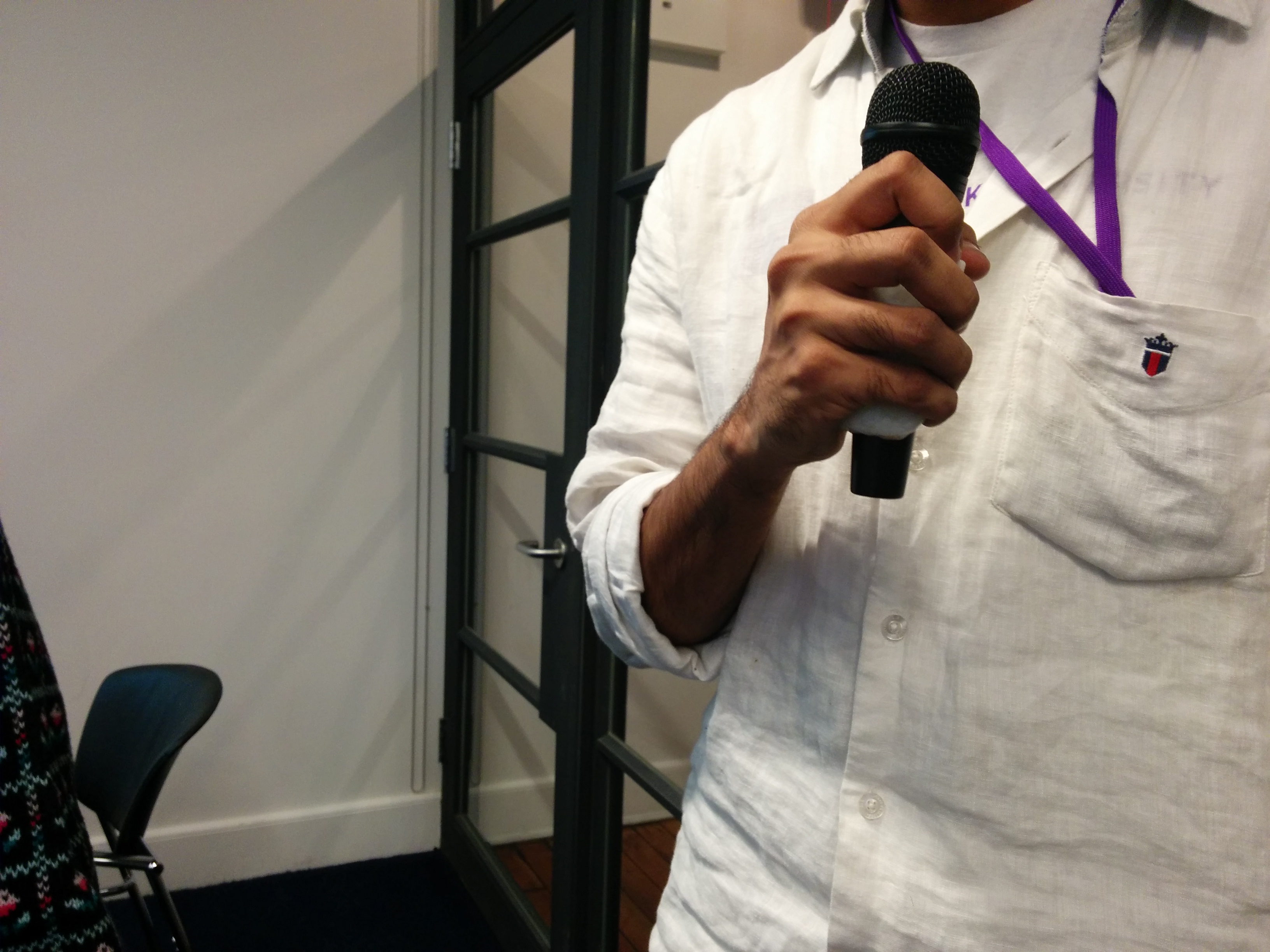
I asked Ben for some advice, and was convinced to start out more basic. My initial instinct was to try and create a curved shaped enclosure right off the bat, but it makes more sense to start simple. Using a normal pre-made enclosure and then attaching it to a microphone clip seemed to be a good first step.

img_20161117_163225

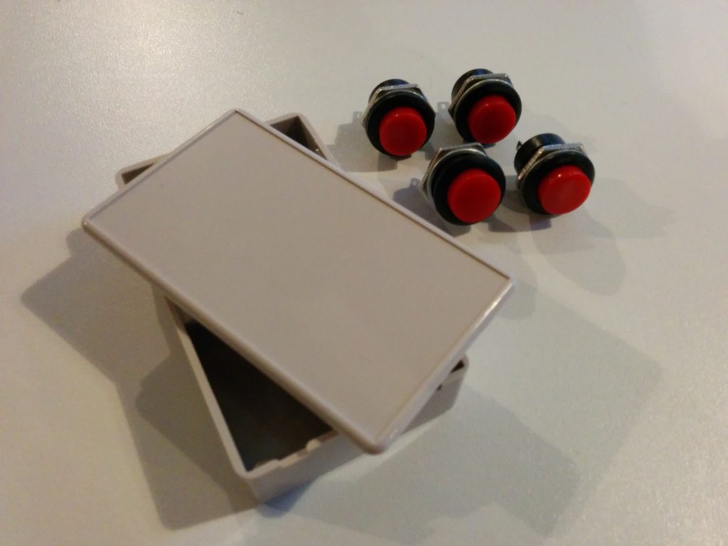
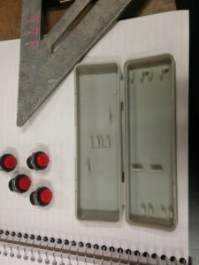
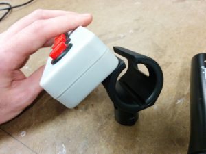
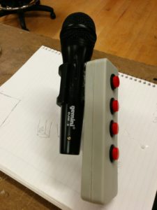
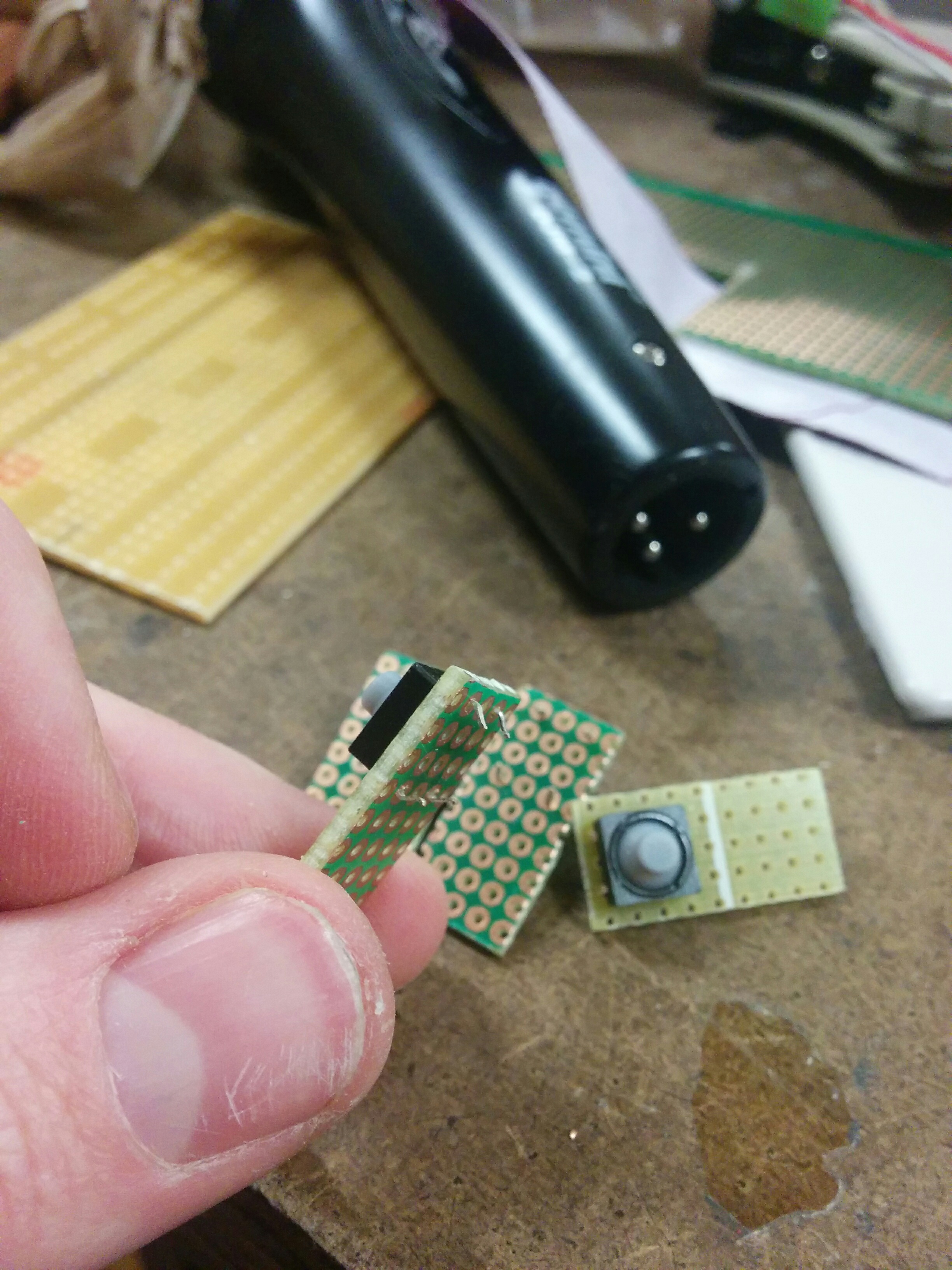
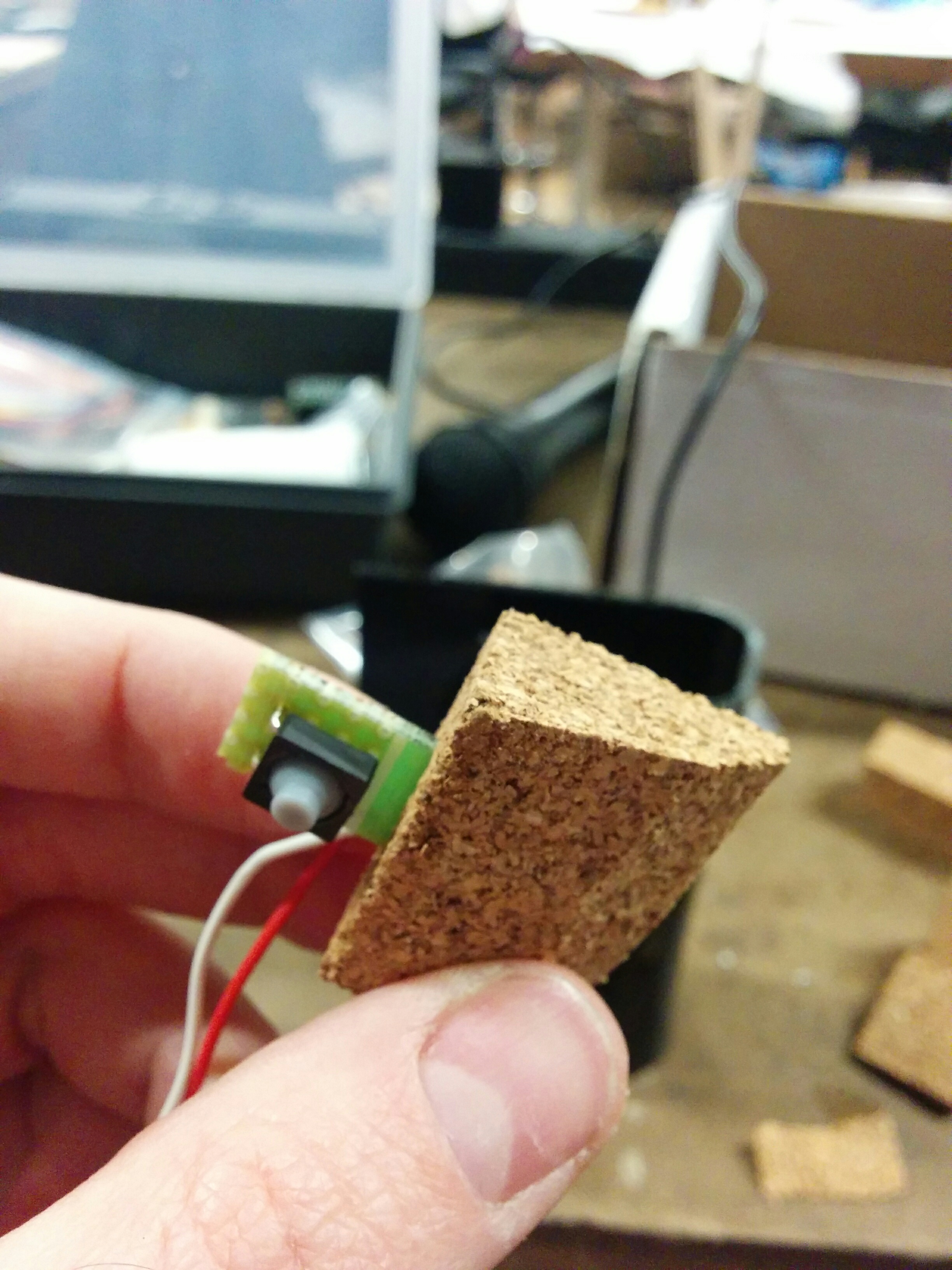
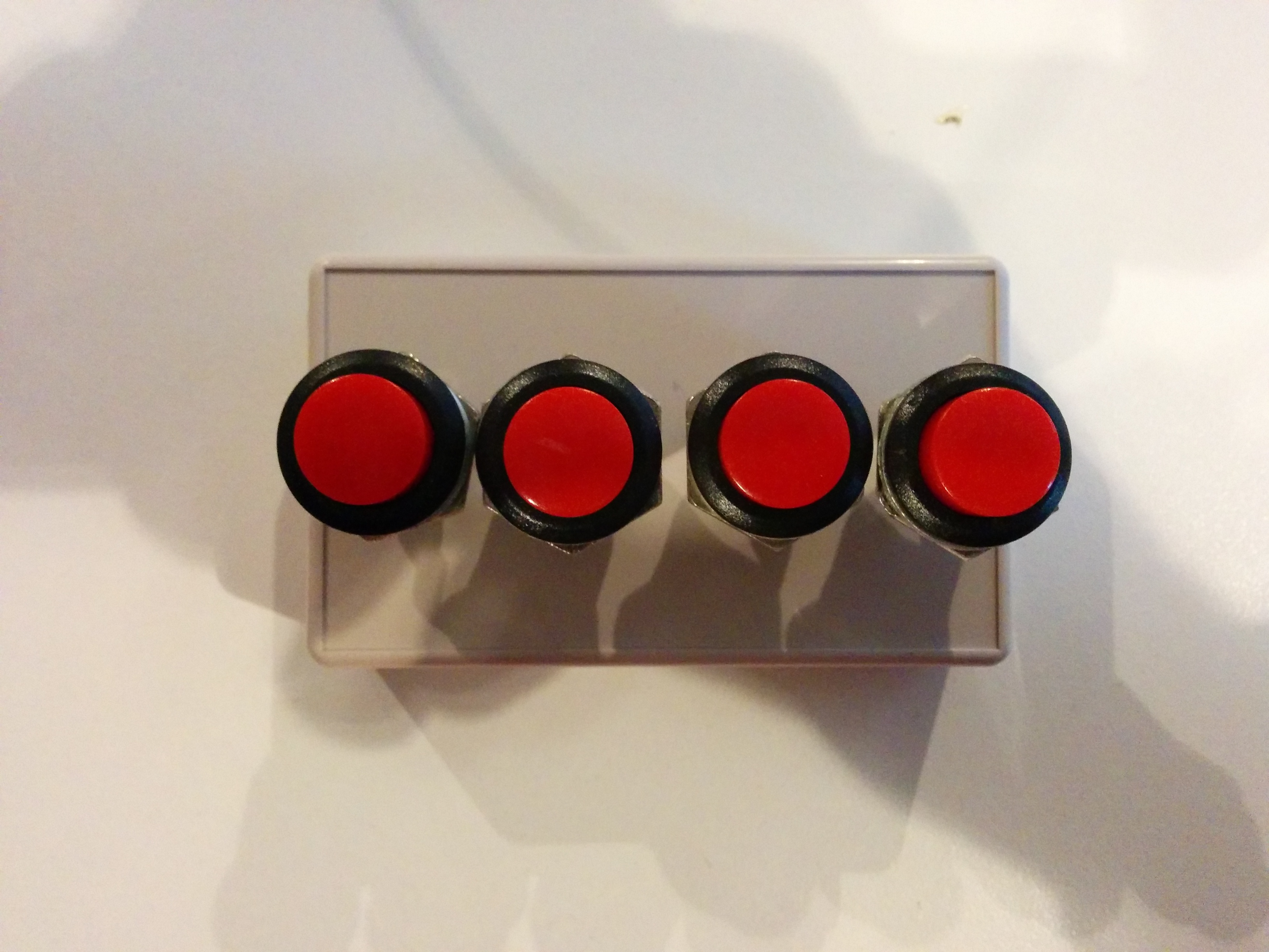
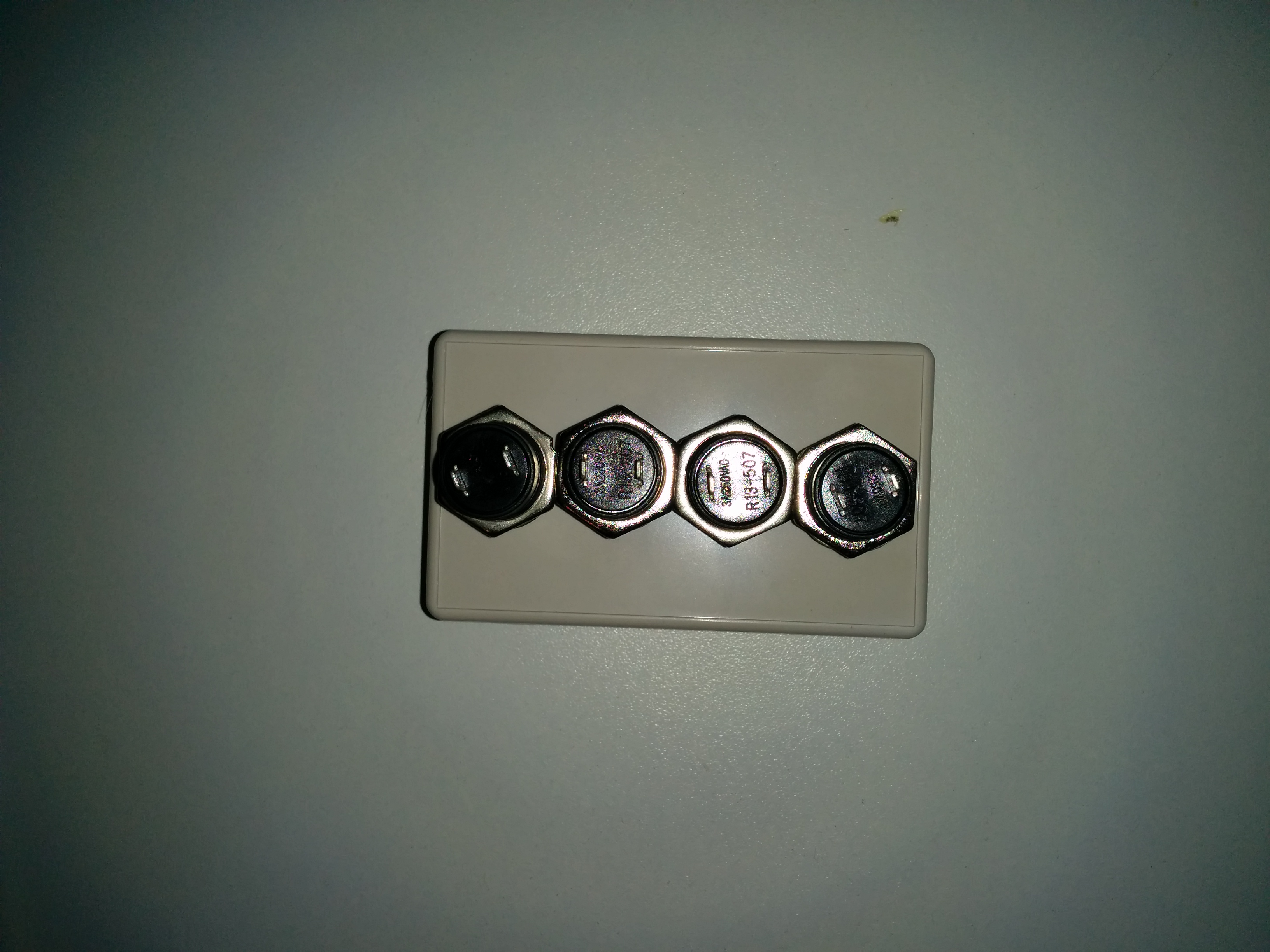
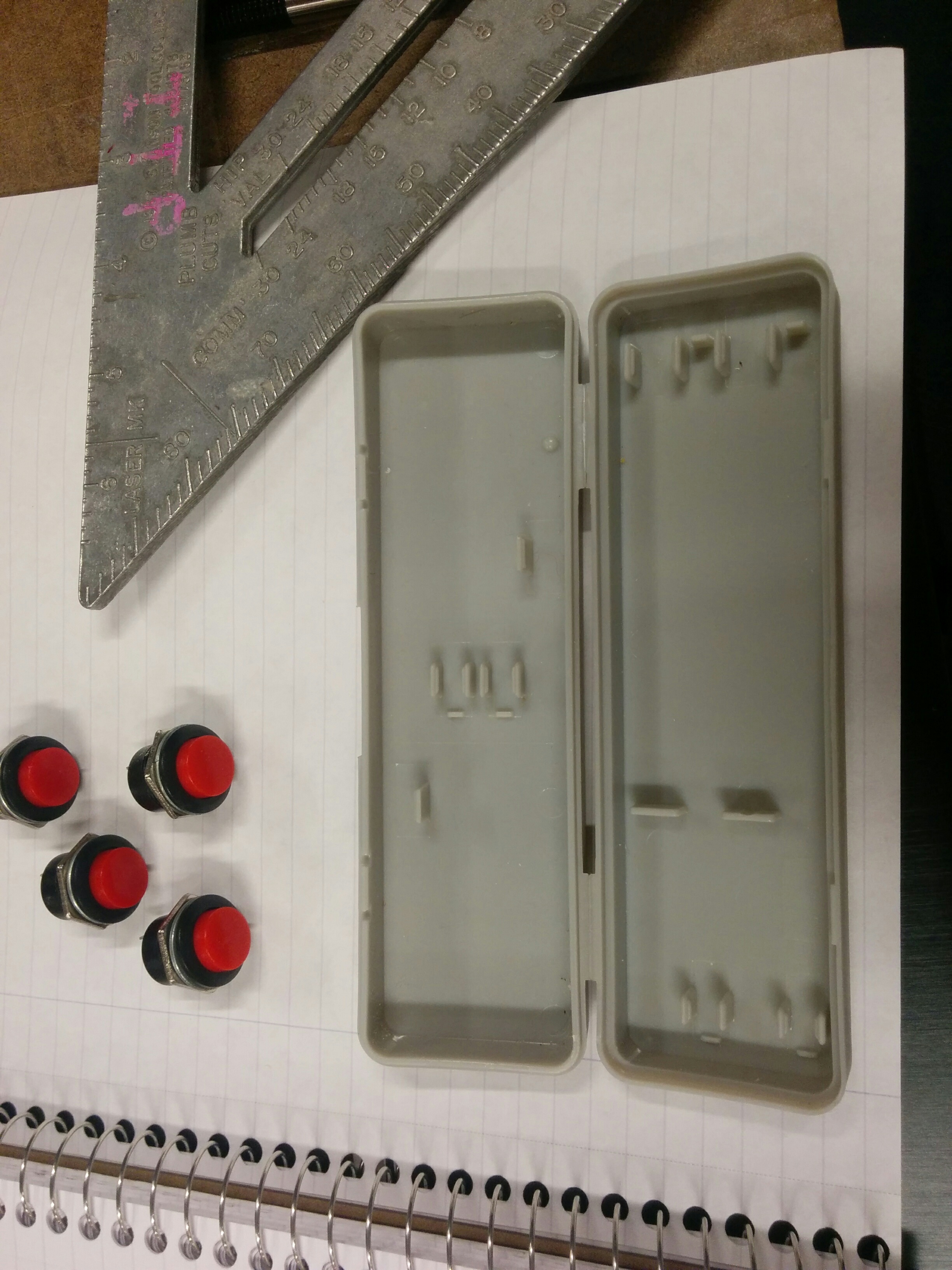
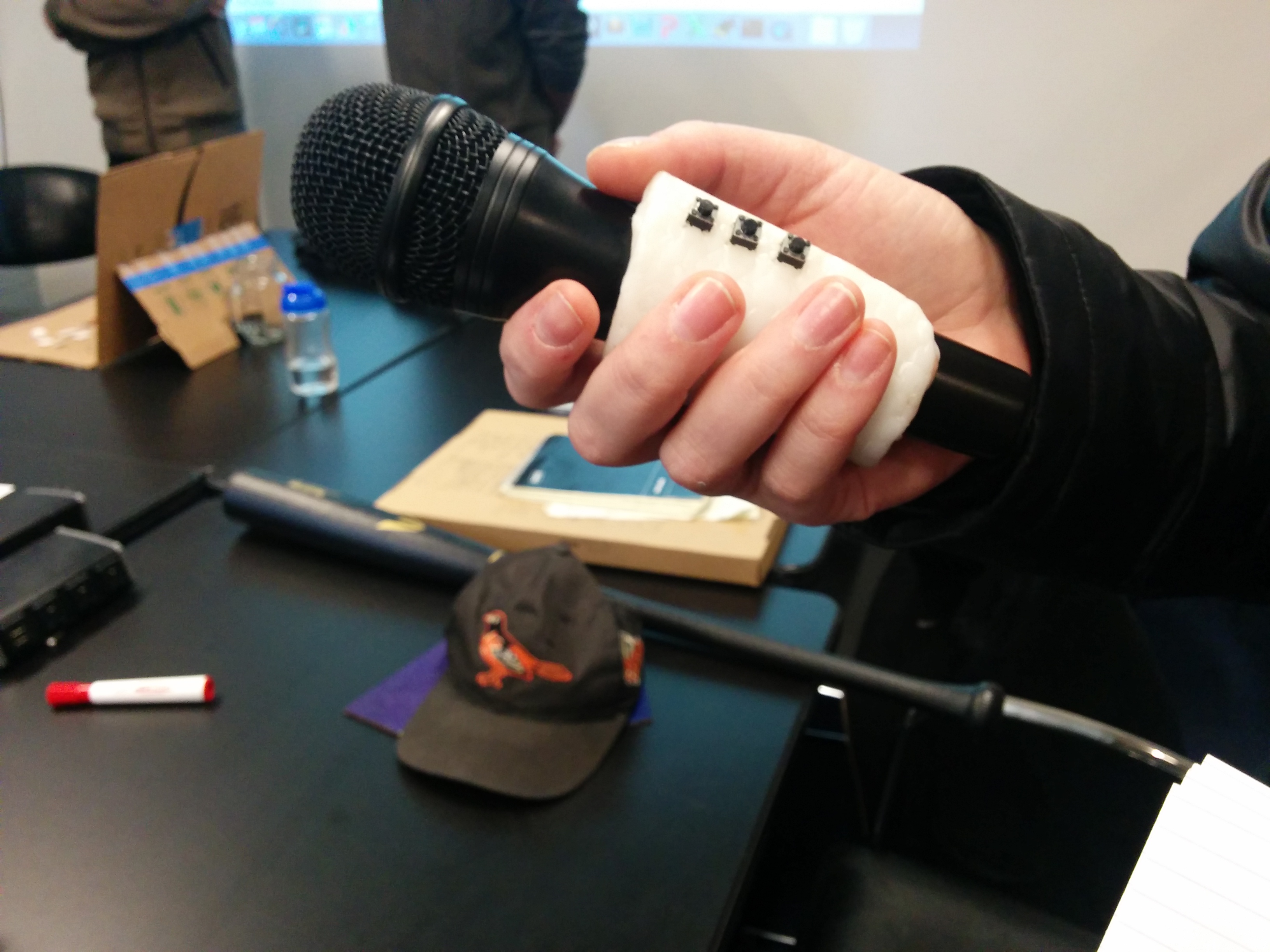
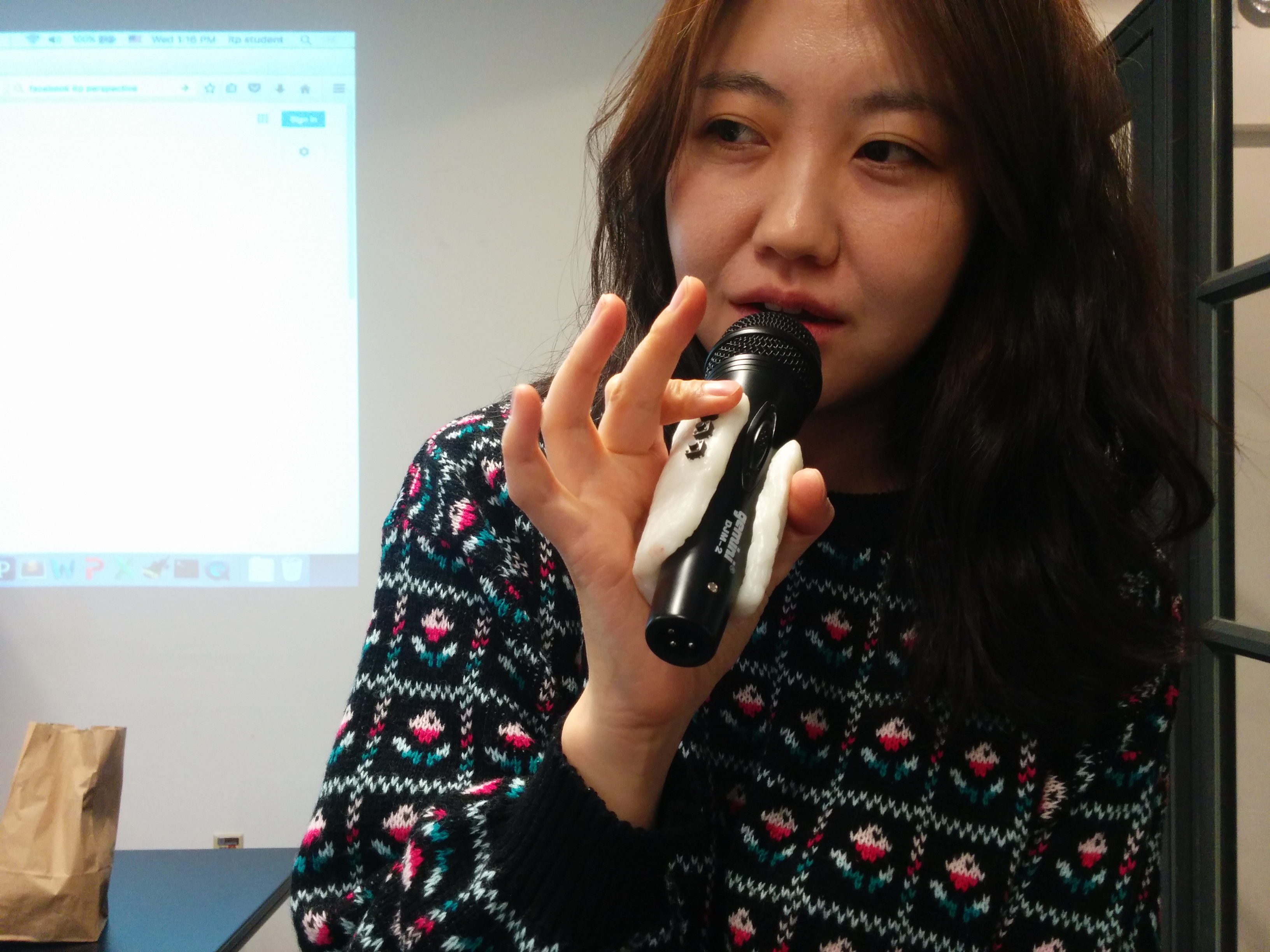
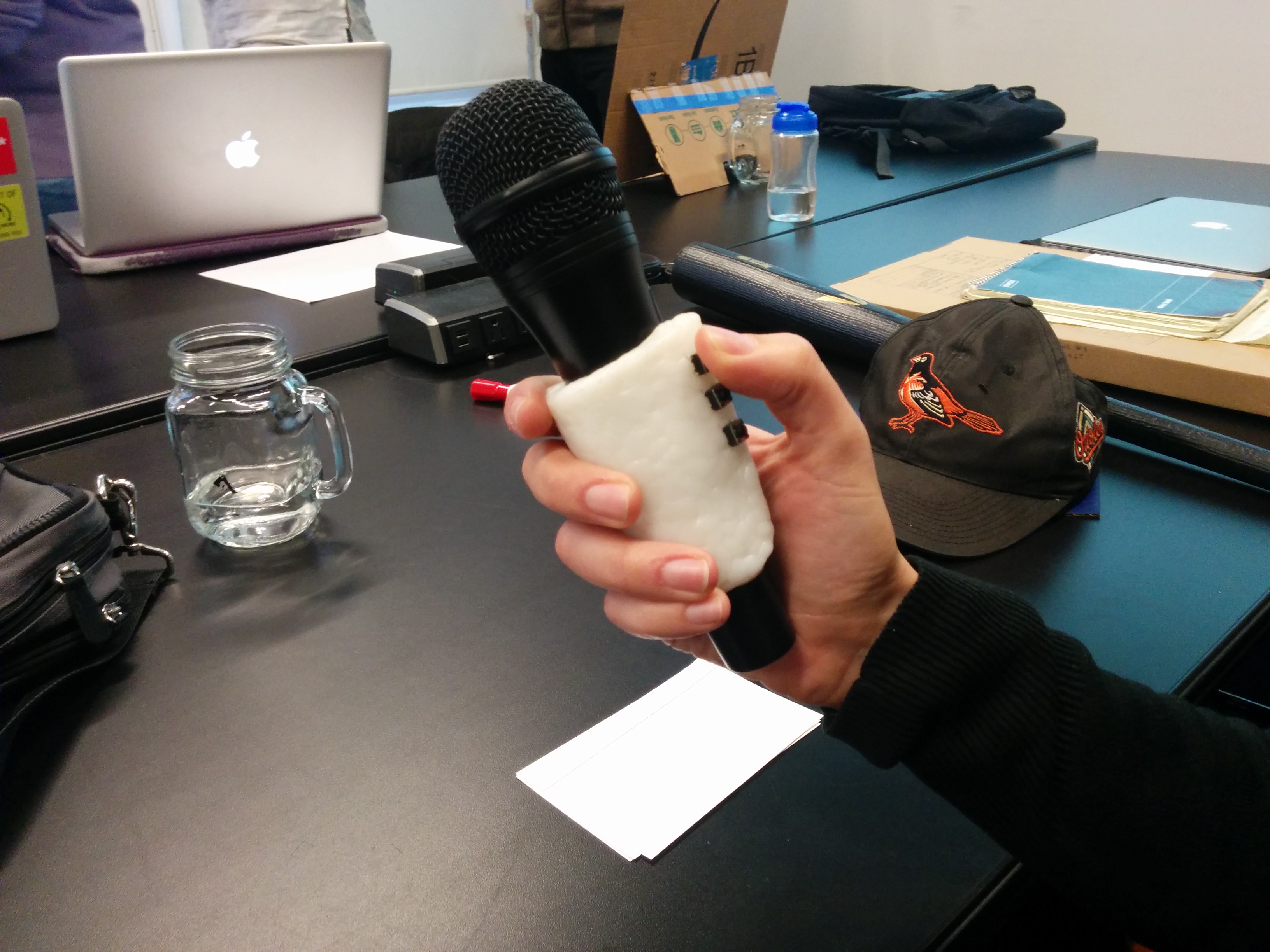
I went to Tinkersphere and bought a project enclosure that complimented the size of my microphone clip, and then bought surface mount buttons for it. They were the rare kind that make no noise when you press them (if I am using this with a microphone, it is best to avoid clicky noises). With these two constraints, my choices were made fairly quickly for me. However, I wasn’t so sure about the spacing:
img_20161117_163505 img_20161117_163615img_20161118_142300 img_20161118_142336

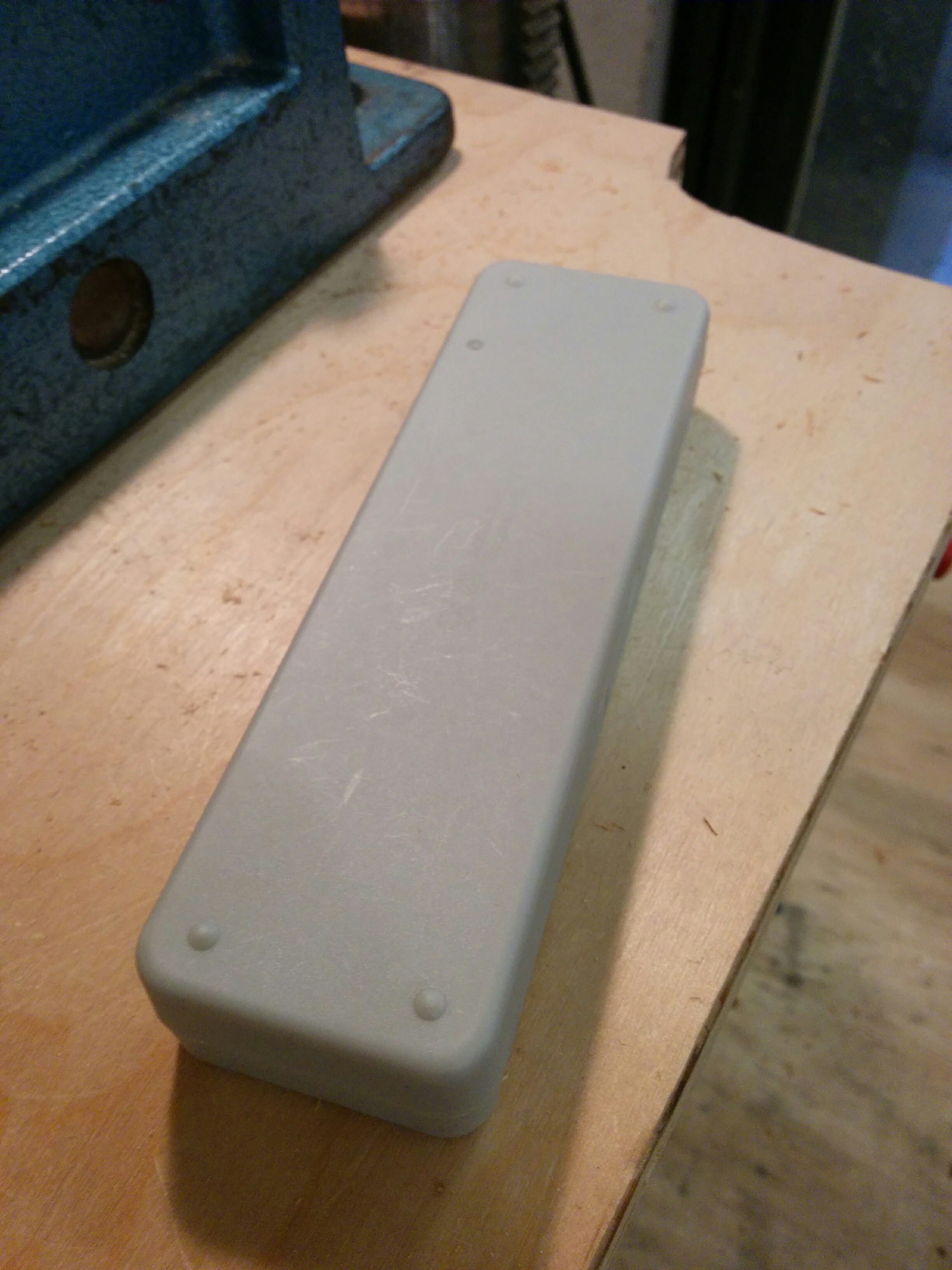
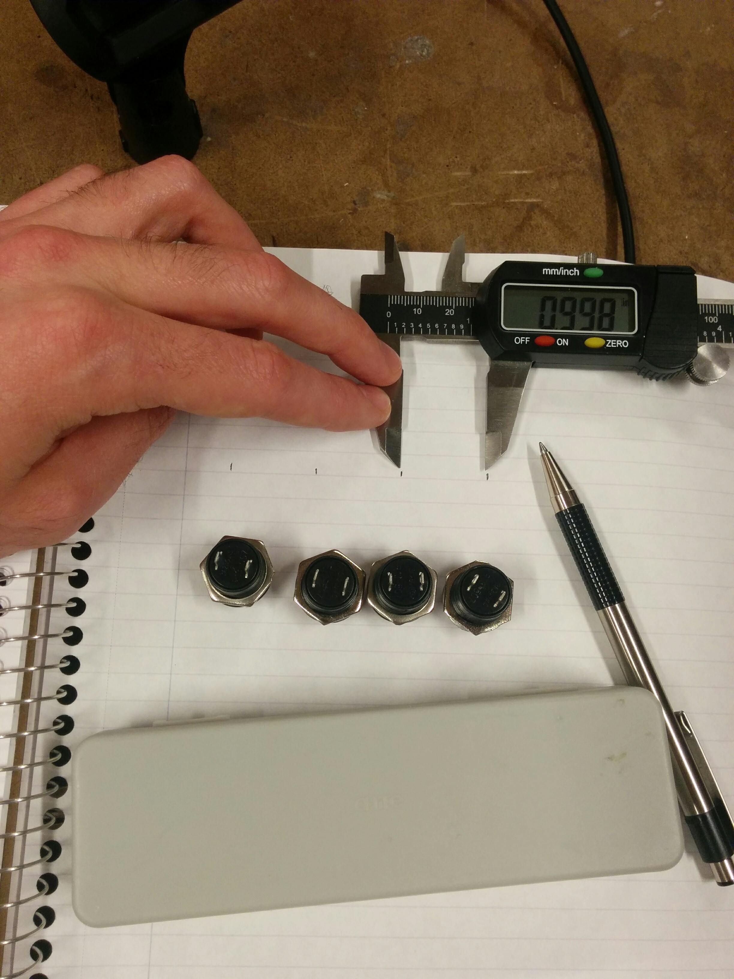
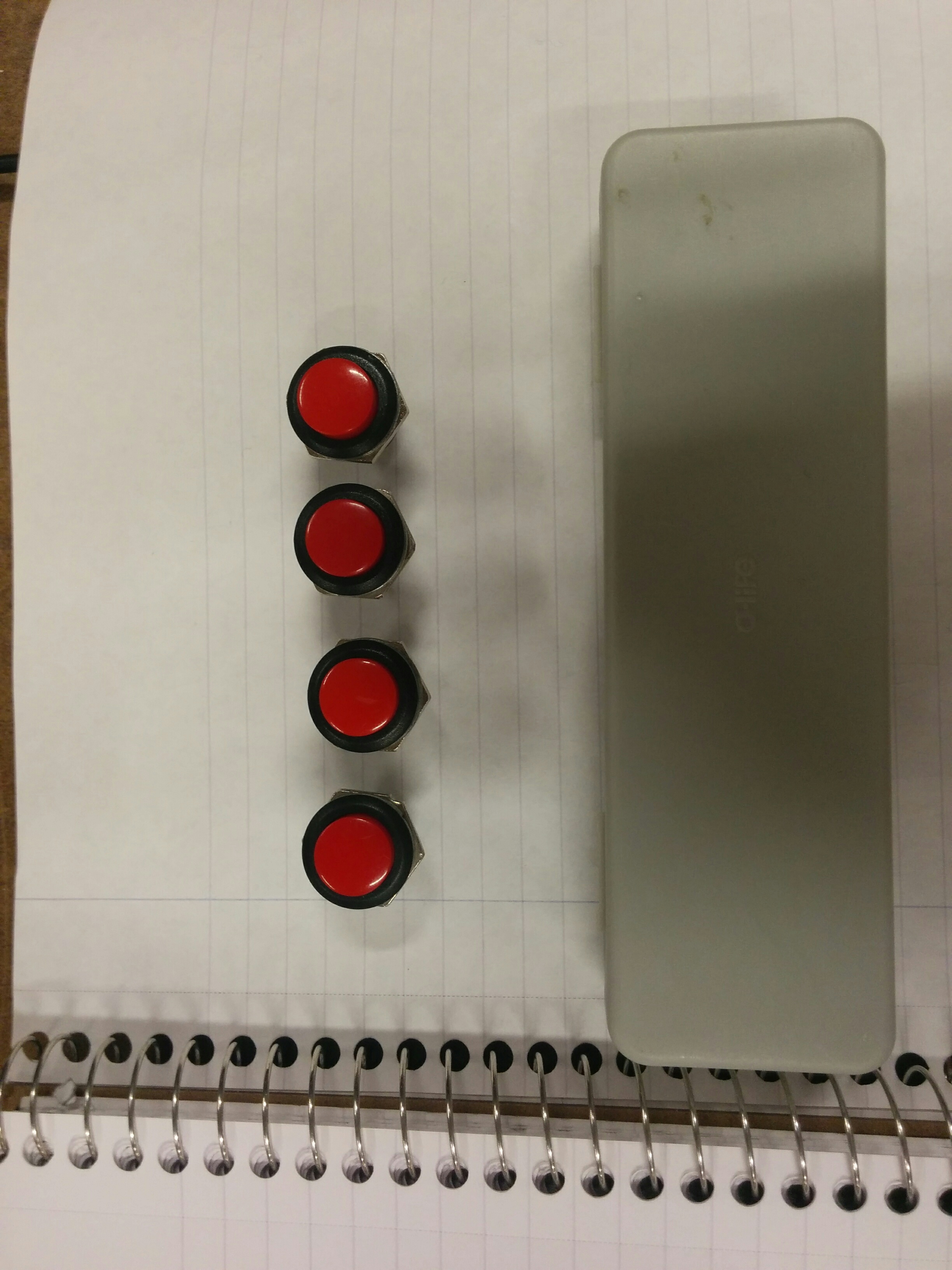
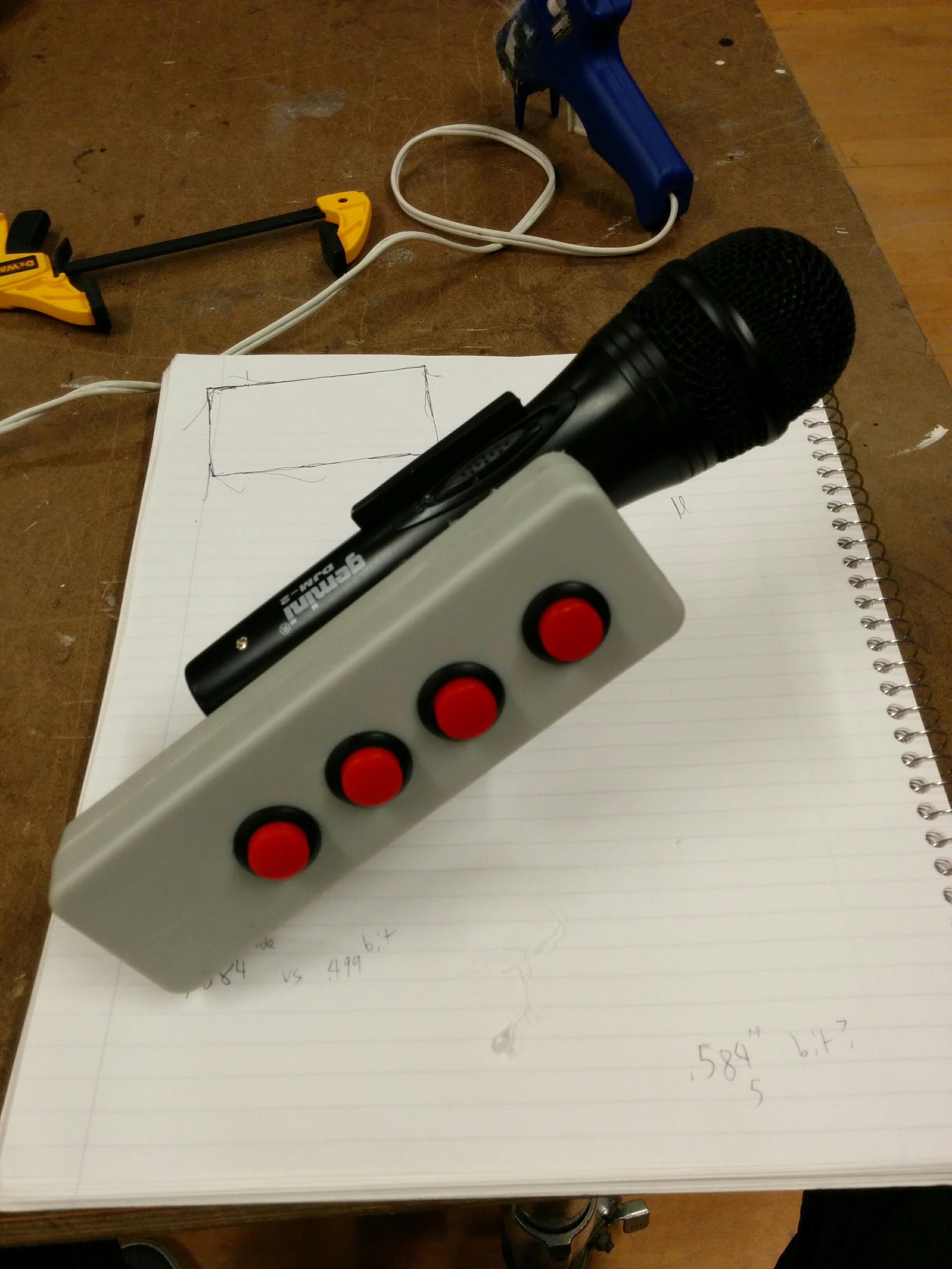
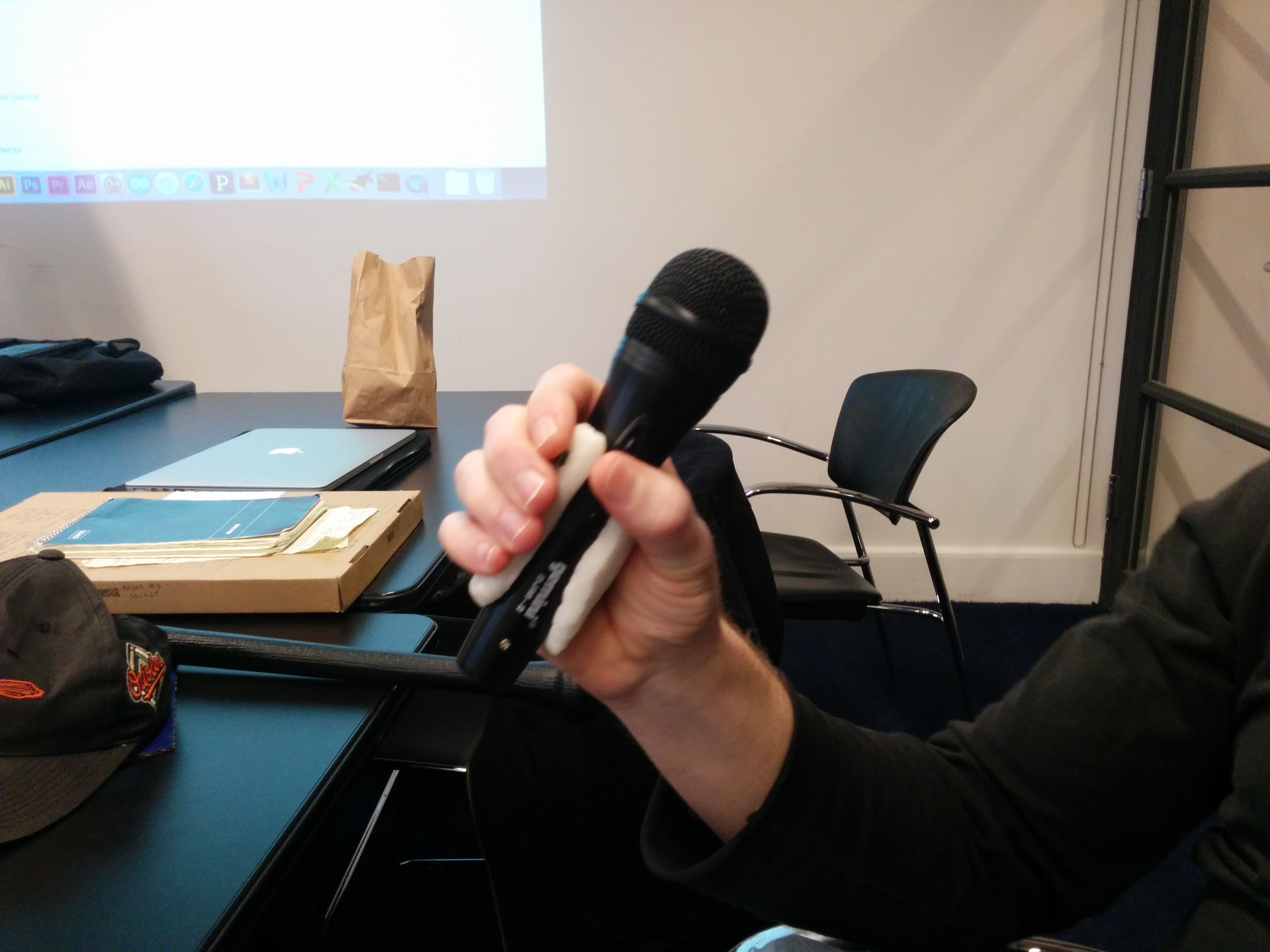
While perhaps technically possible to fit all the buttons onto the surface, I started having second thoughts when I brought everything back to the shop and was able to measure. Luckily, Ben had given me a different enclosure to try out. The more I looked at it the more it made sense:

img_20161118_150907img_20161118_143902

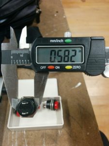
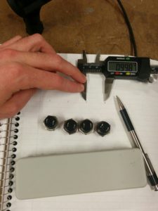
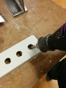
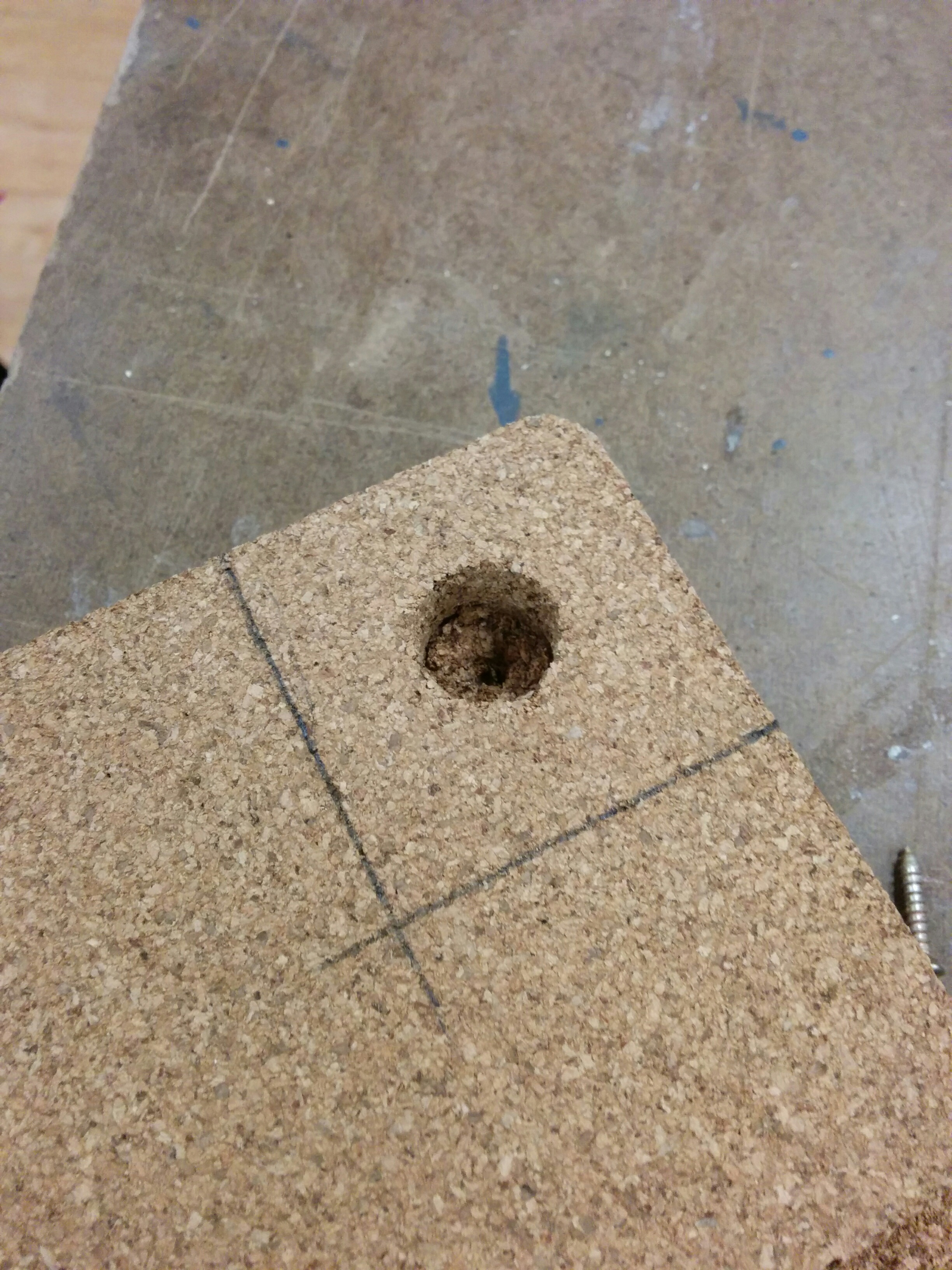
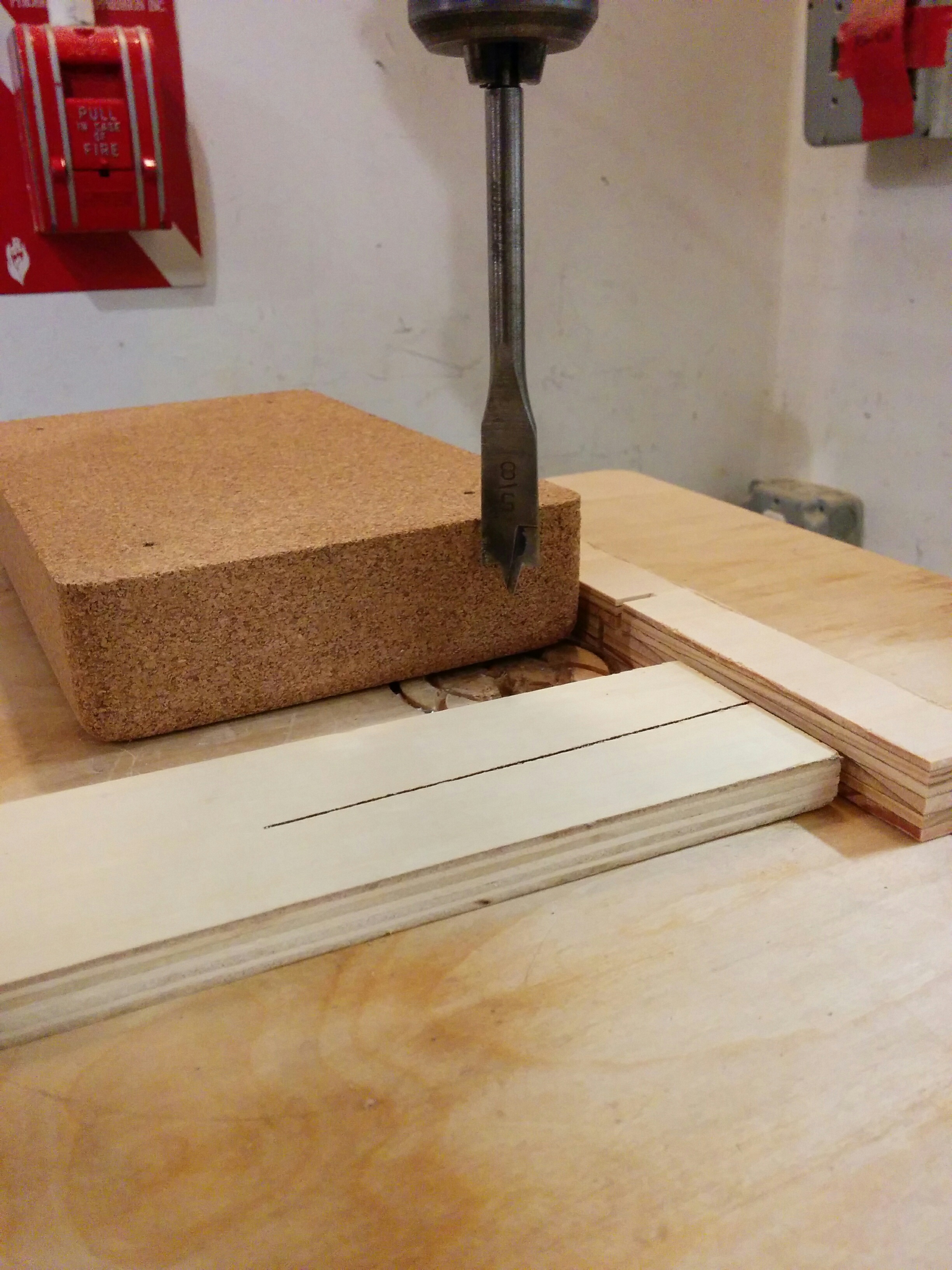
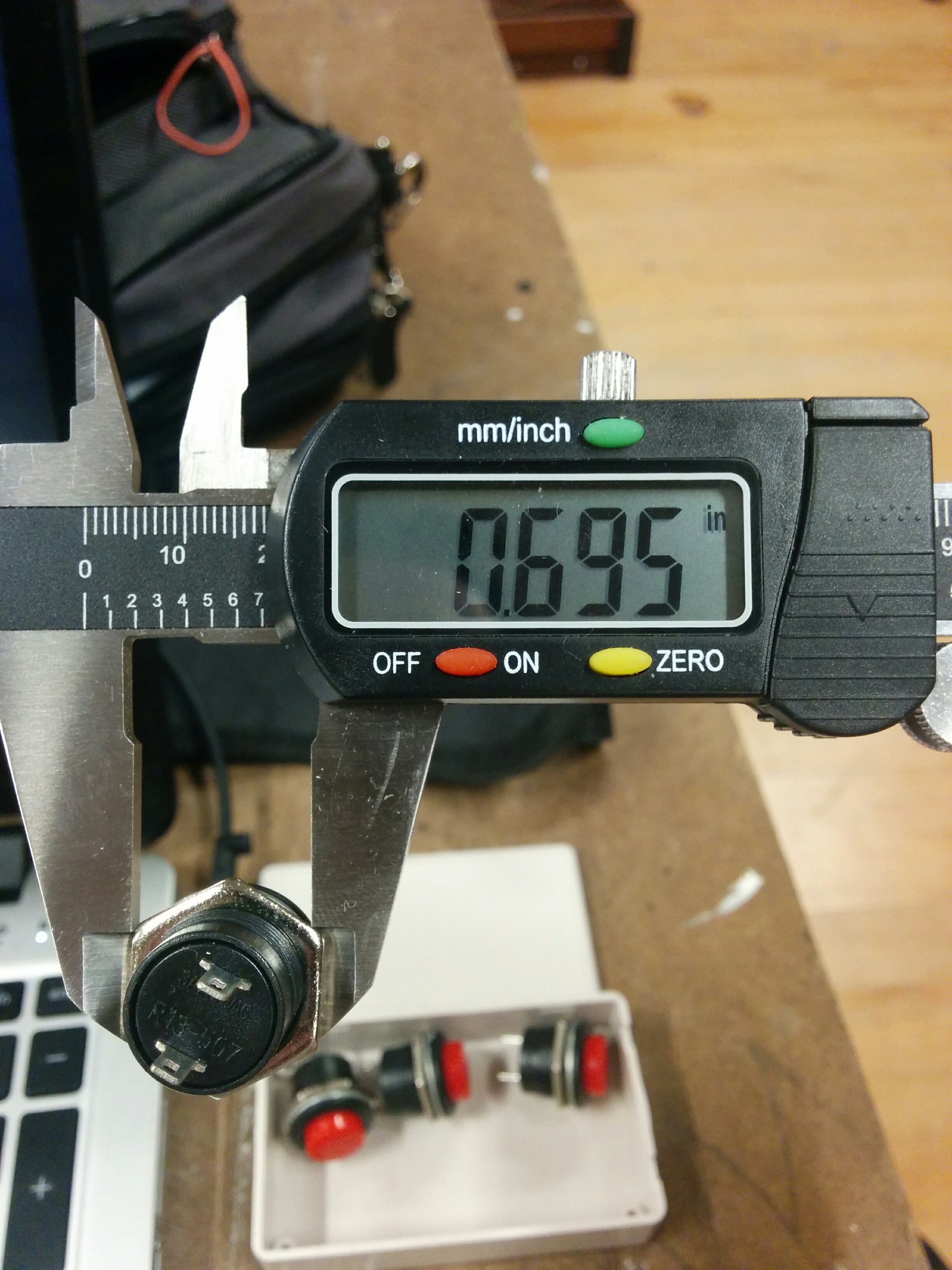
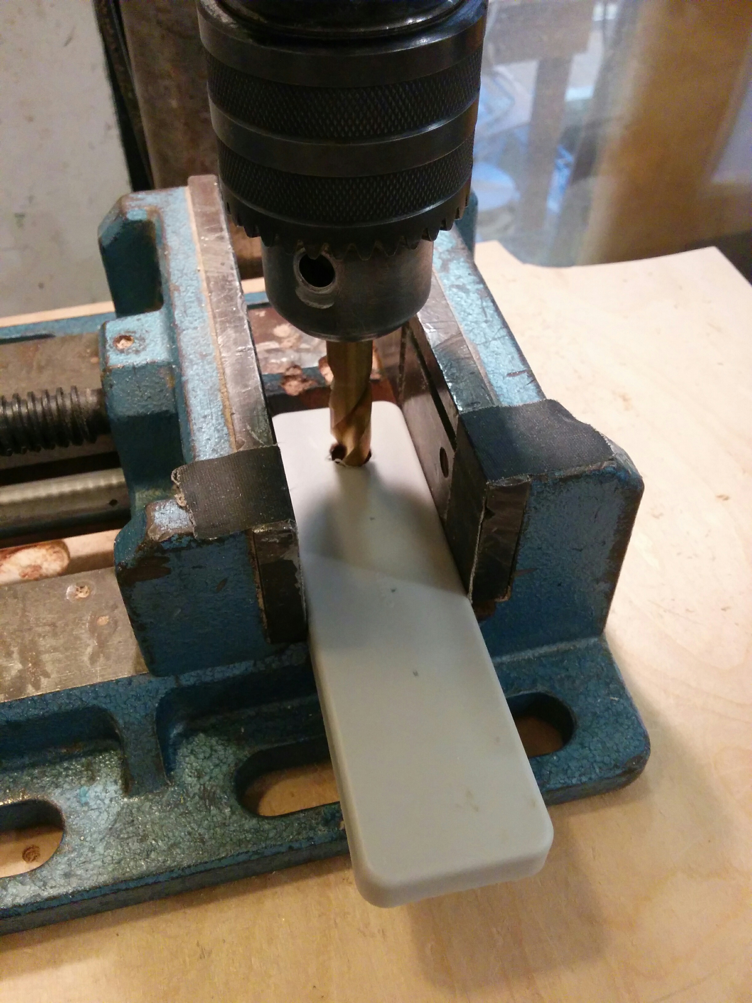
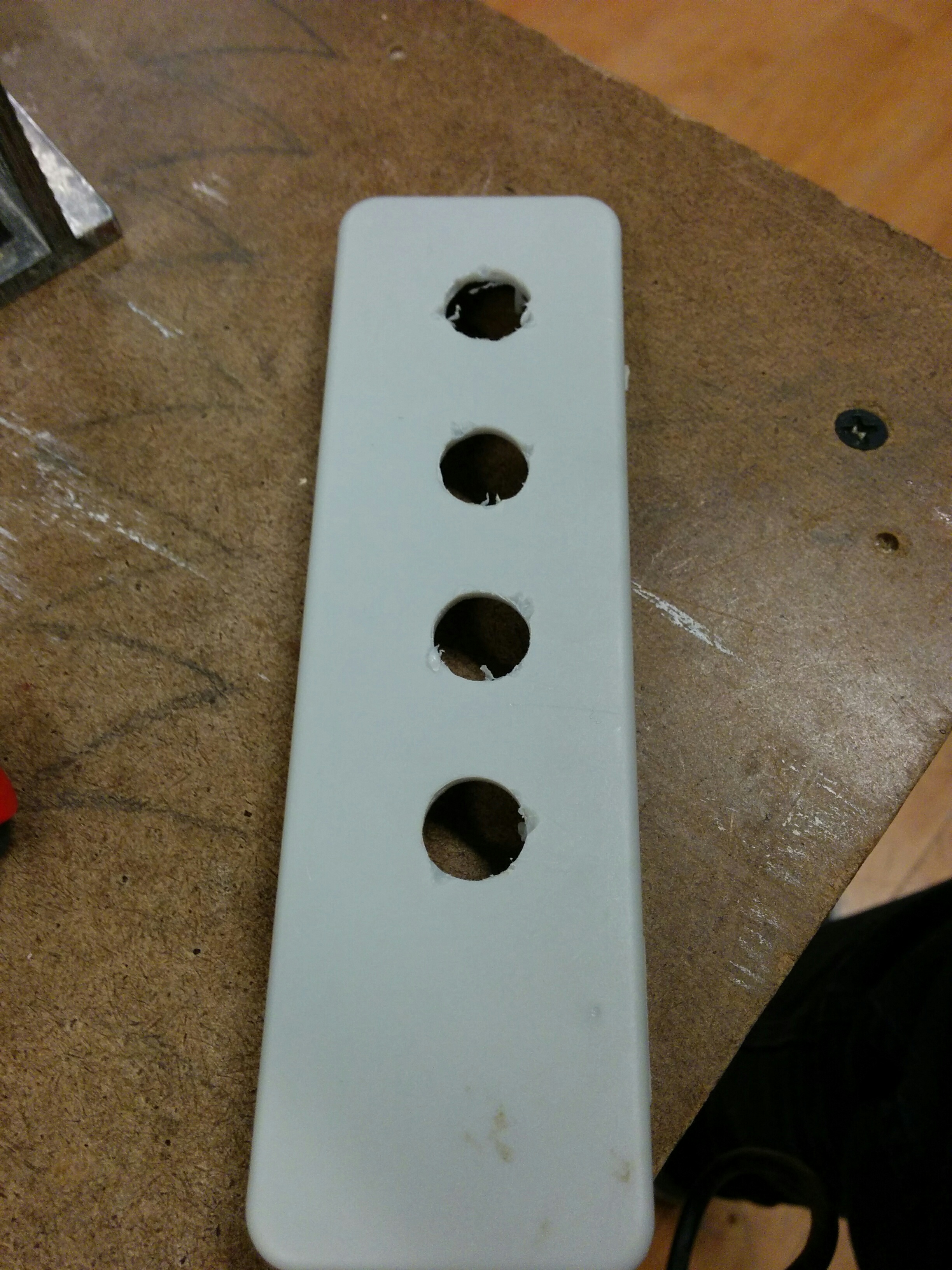
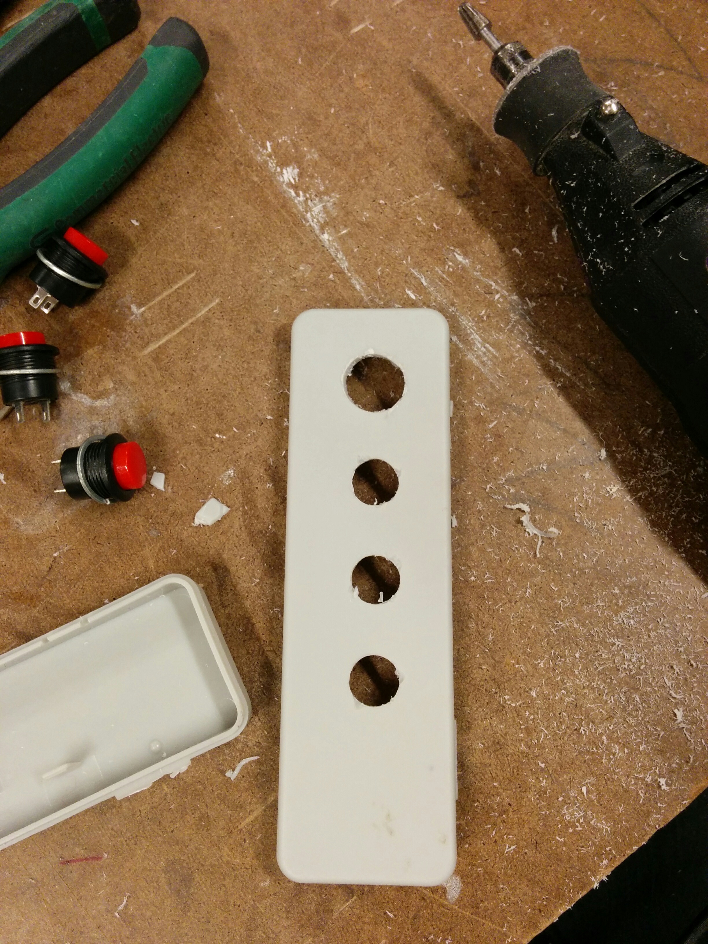
“Small is hard” kept echoing in my head, and even though larger I felt like this could work decently for my play testing. I went to measure out the distance between buttons and started making some holes on the drill press.

img_20161118_143530 img_20161118_143711 img_20161118_144138 img_20161118_145826 img_20161118_150809

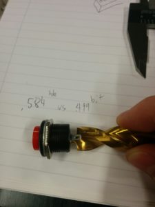
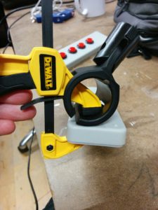
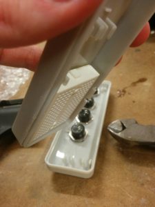
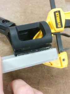
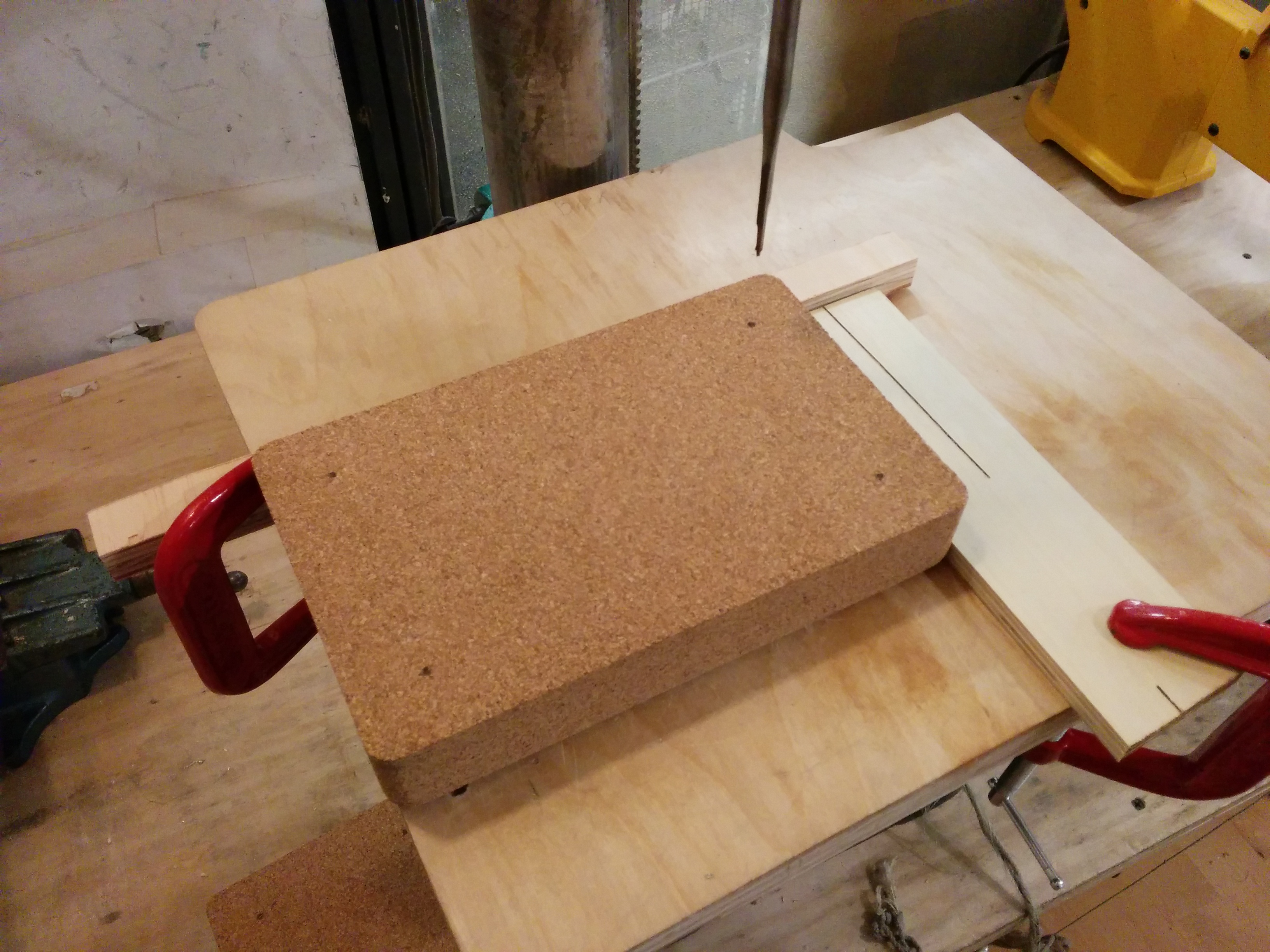
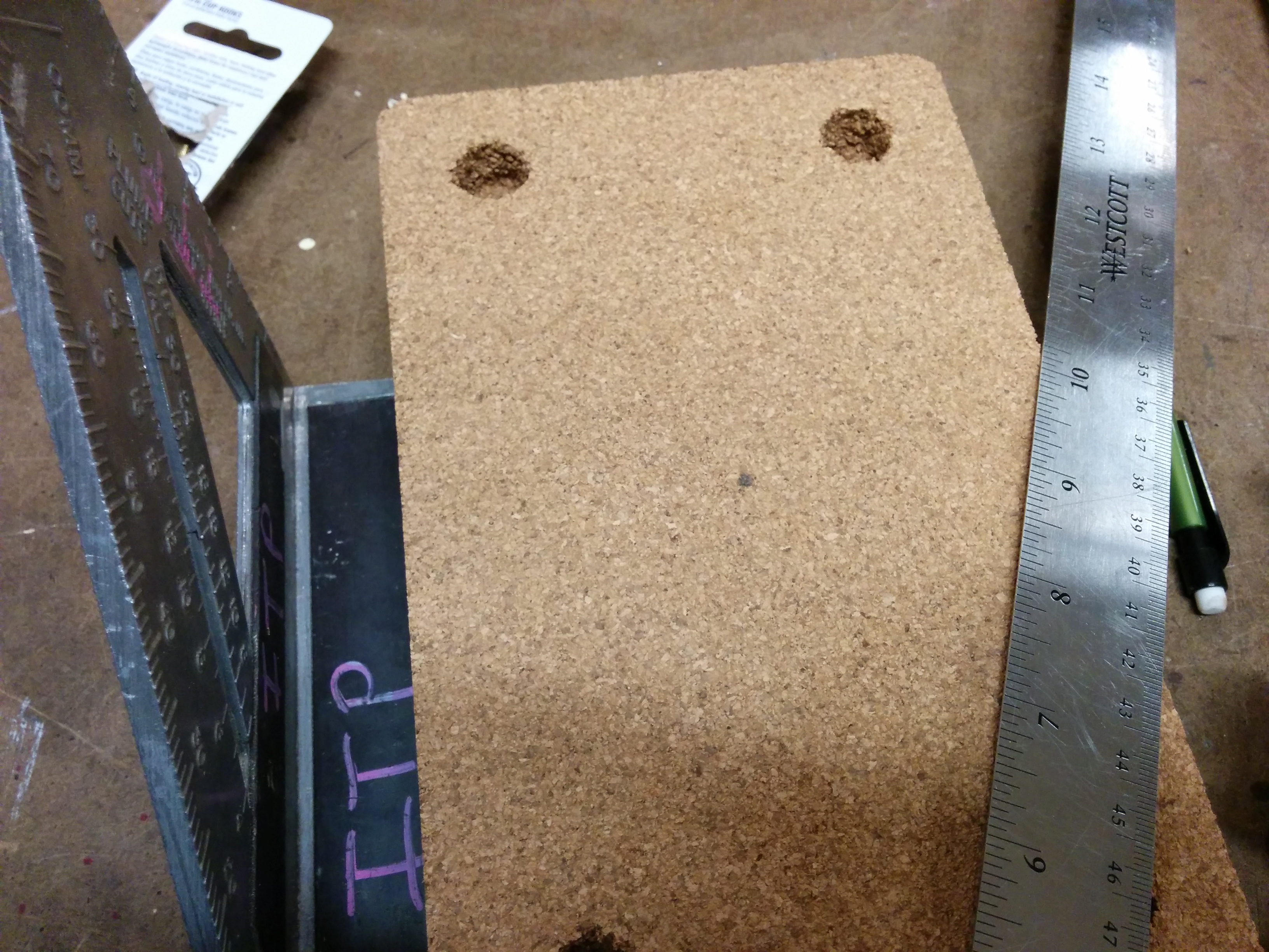
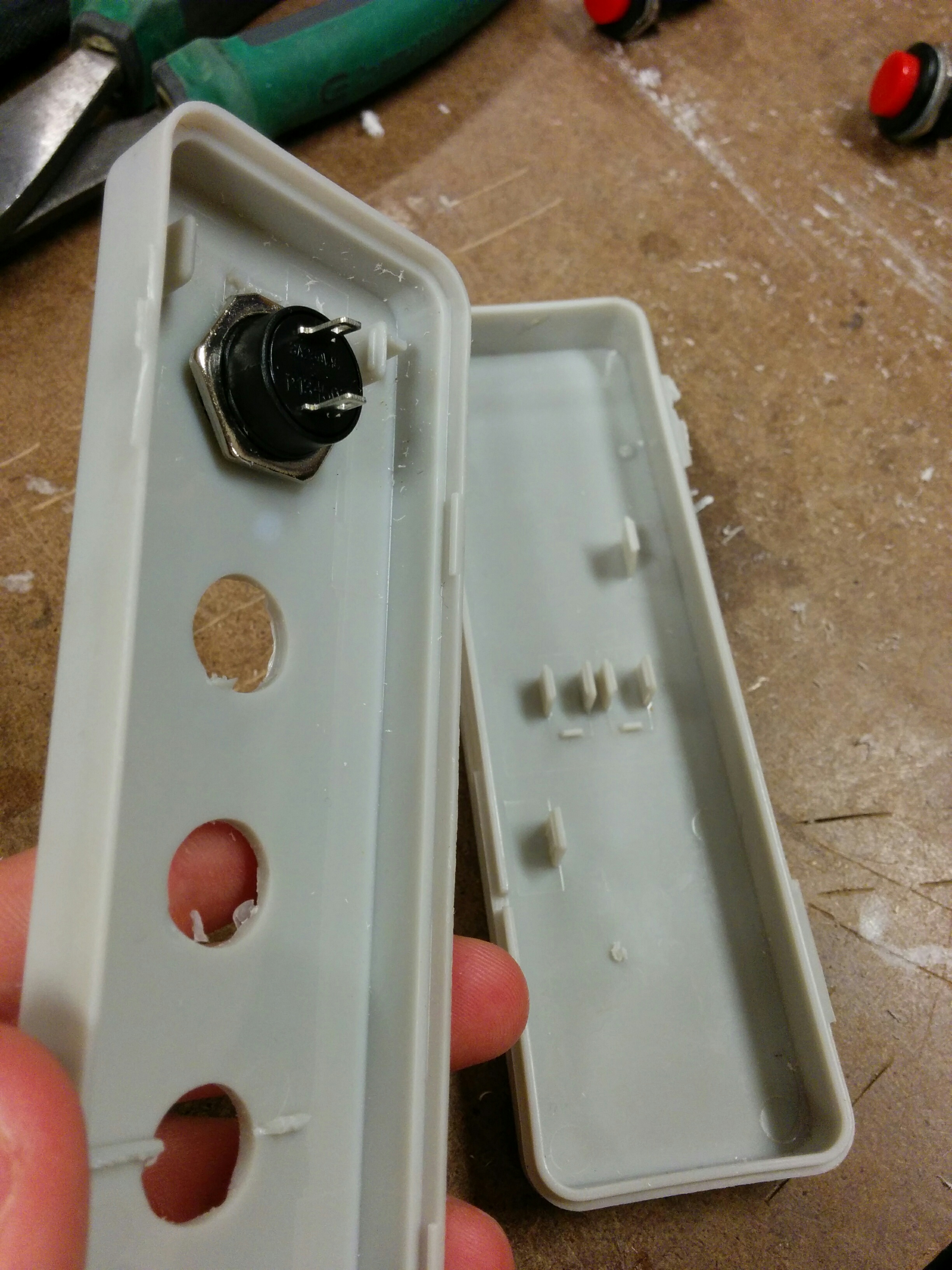
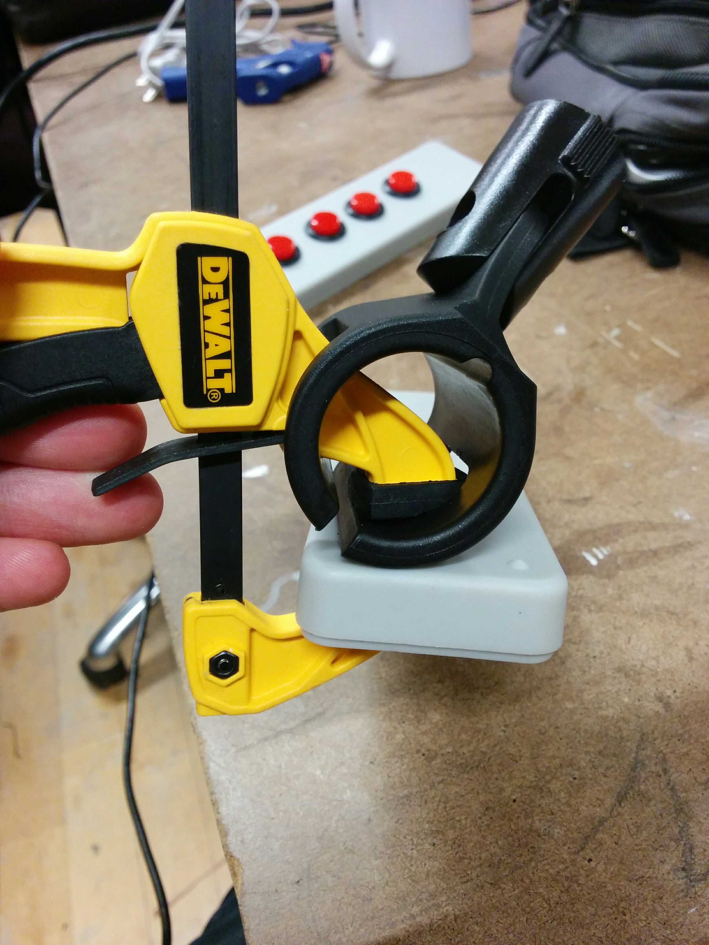
The box had two hinges made of plastic, one broken. Trying to clamp it effectively weren’t going well, and the one good hinge was looking a little flimsy so I just separated the pieces. Made for a much more secure clamp. Also, as you can see from my notes, I could only find a 1/2″ bit in the shop, and nothing larger. Would have to do for now, as John explained that the larger spade bits we have in the shop shouldn’t be used on plastic.

img_20161118_151948 img_20161118_151955

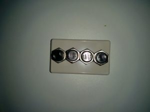
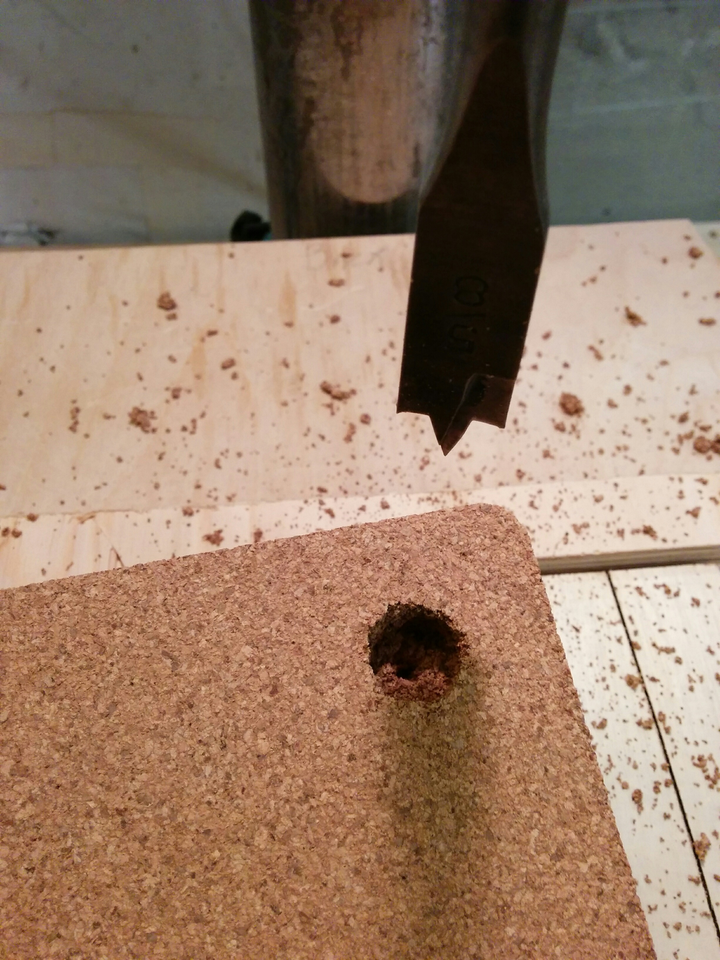
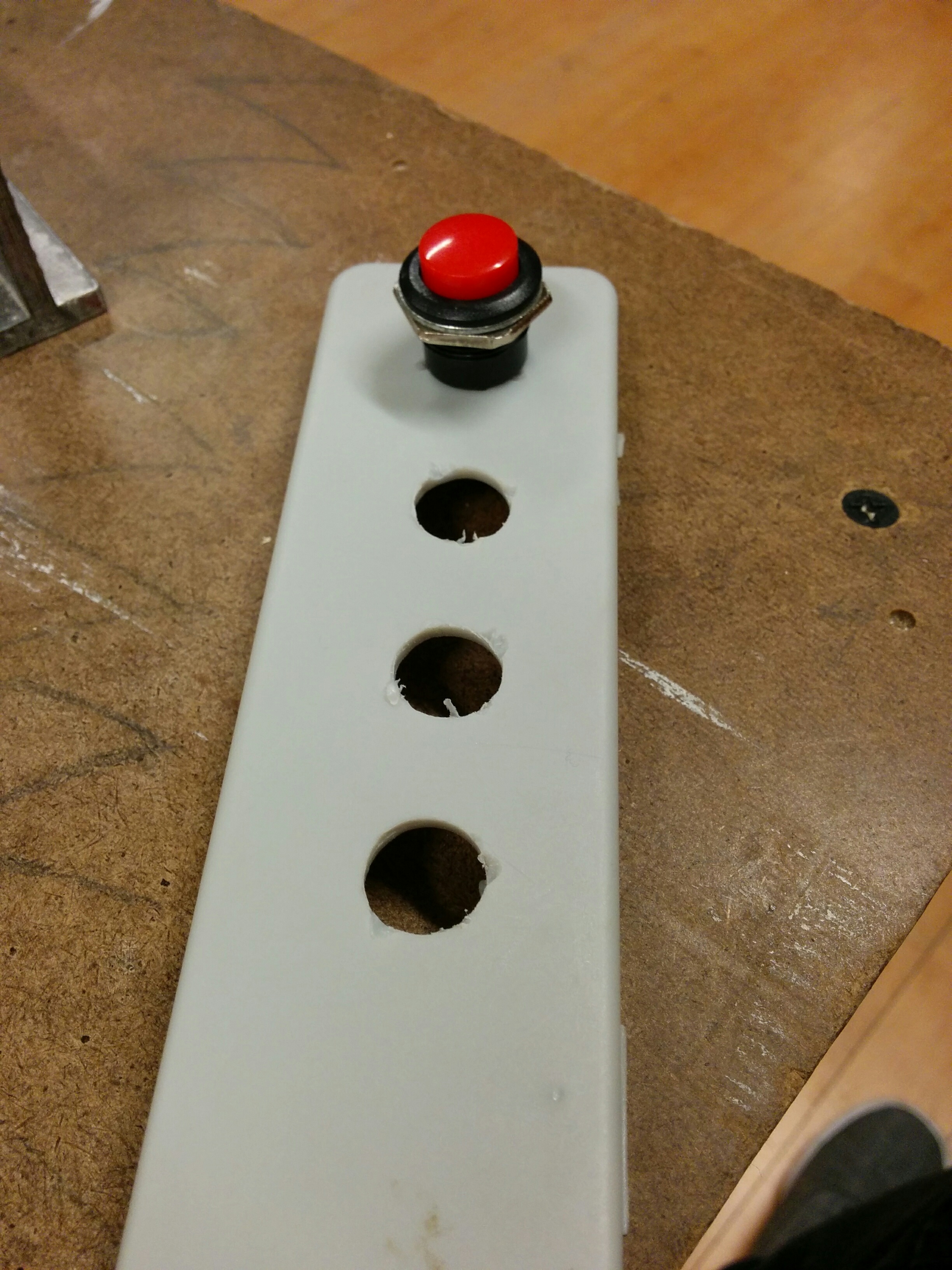
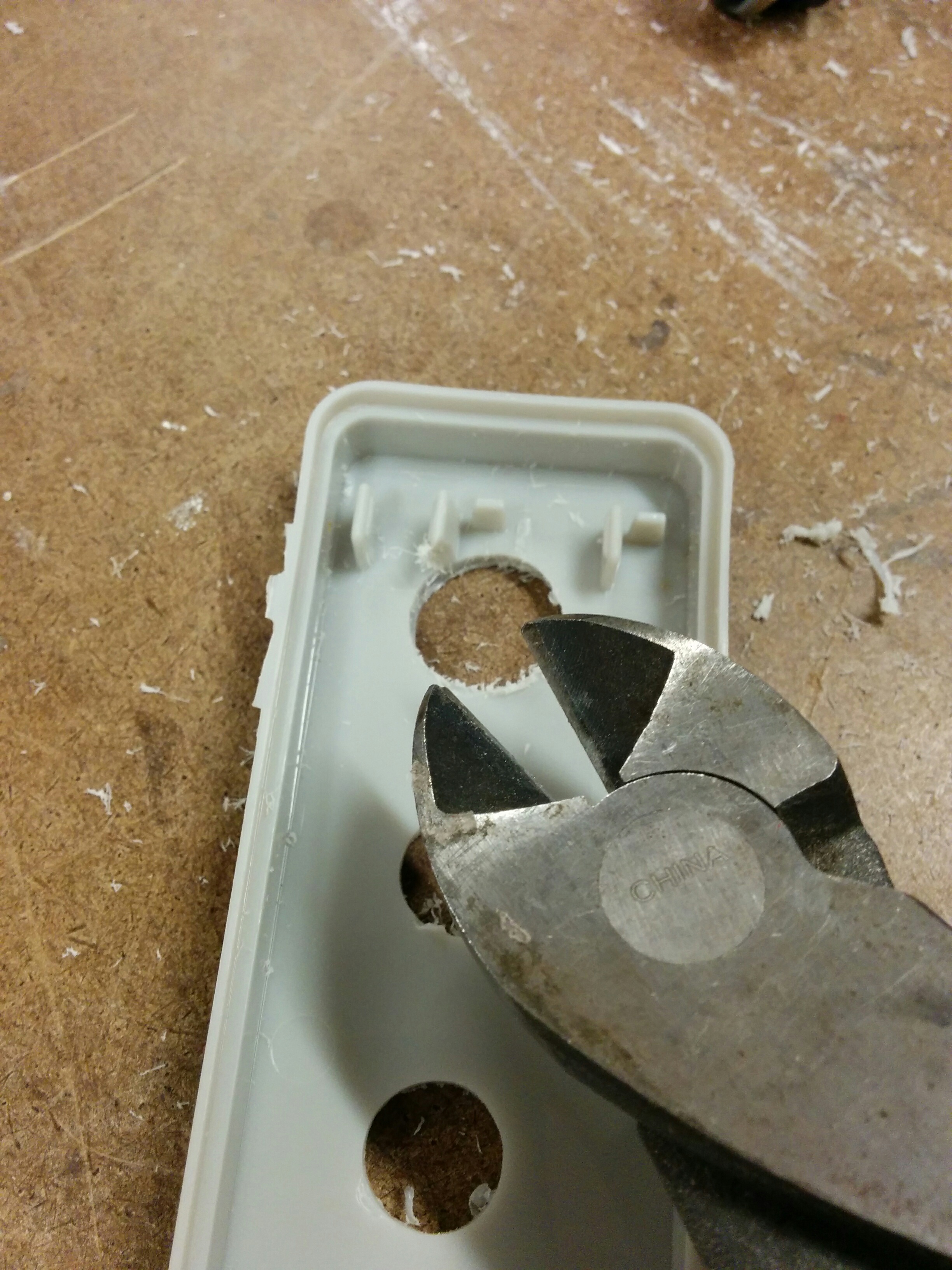
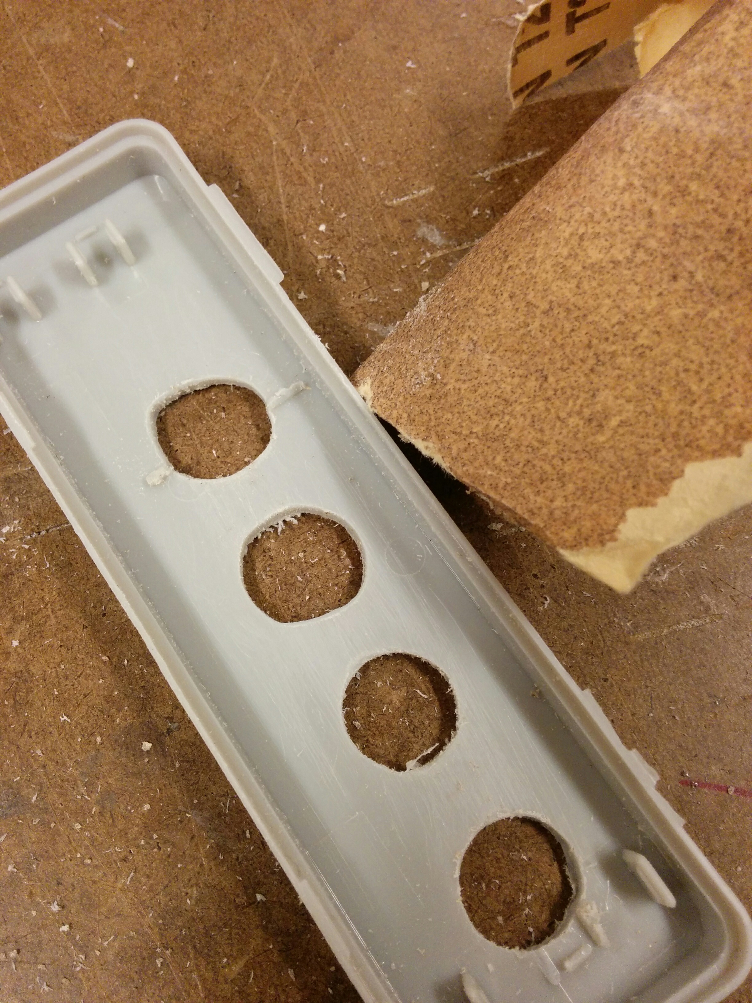
The holes came out alright, but I was hoping that maybe I could just kind of force the buttons in. The plastic turned out to be much more resilient than to allow that. So I cleaned out the inside pieces of the enclosure and started slowly, piece by piece, expanding one of the holes with the Dremel.

img_20161118_152729 img_20161118_152139img_20161118_153033img_20161118_153047img_20161118_153208

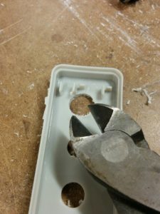
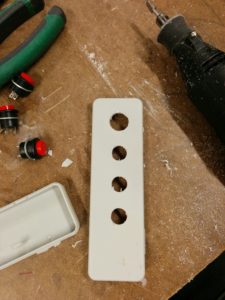
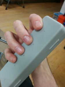
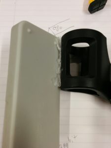
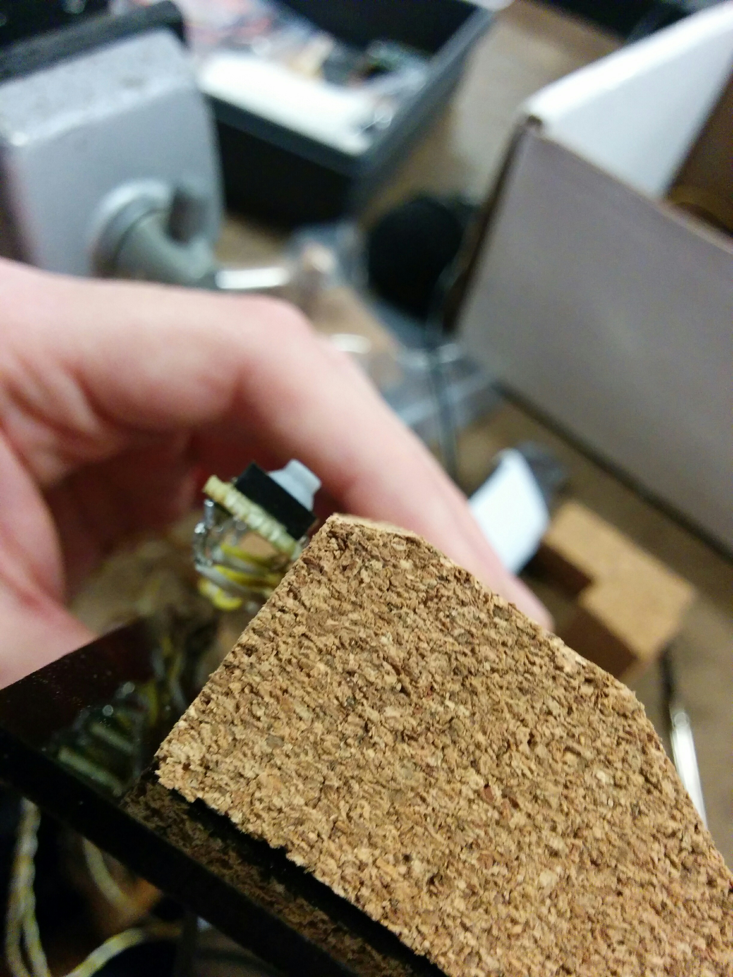
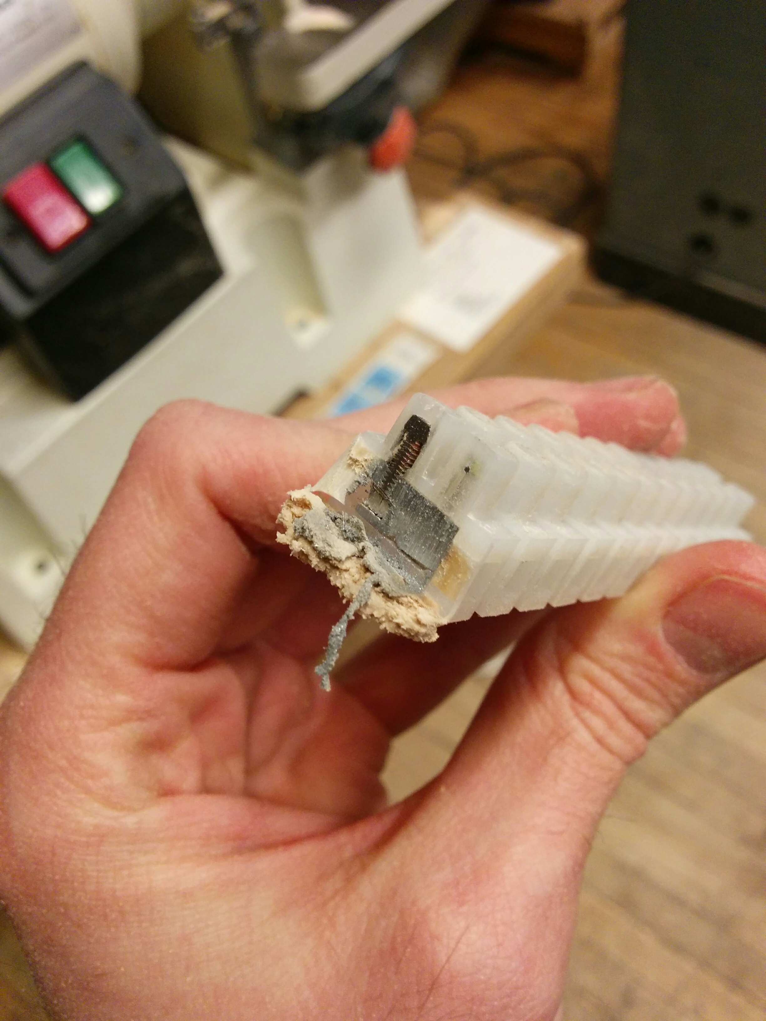
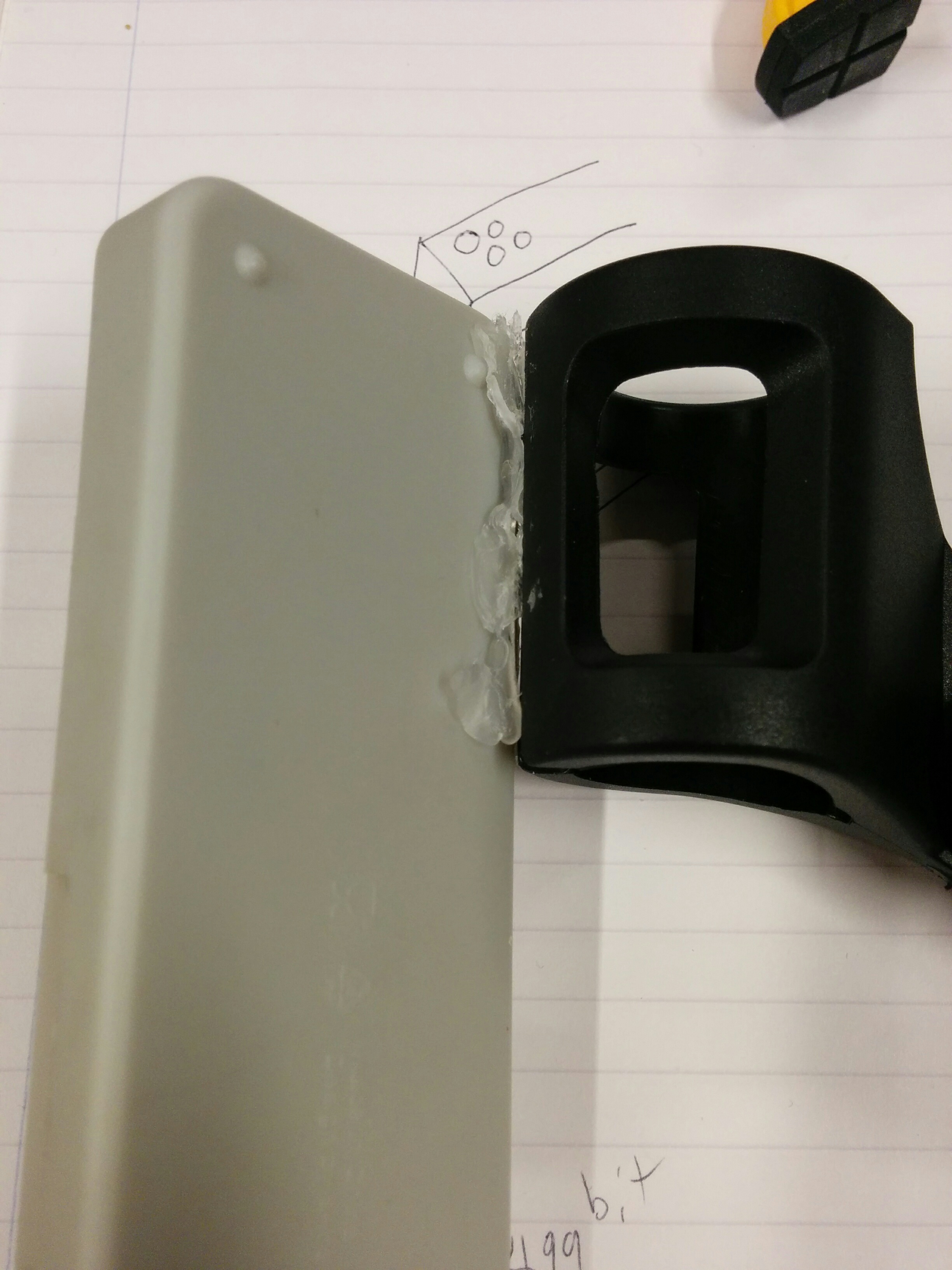
It was more Dremeling than I thought I would have to do. You can pretty clearly see the hole size difference with the naked eye. It wasn’t too bad, but if I was making multiples this is where I would be kicking myself and/or going on a quest for the perfect bit.

img_20161118_155125

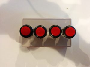
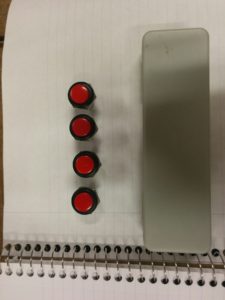
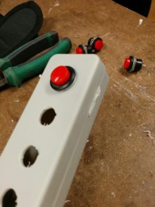
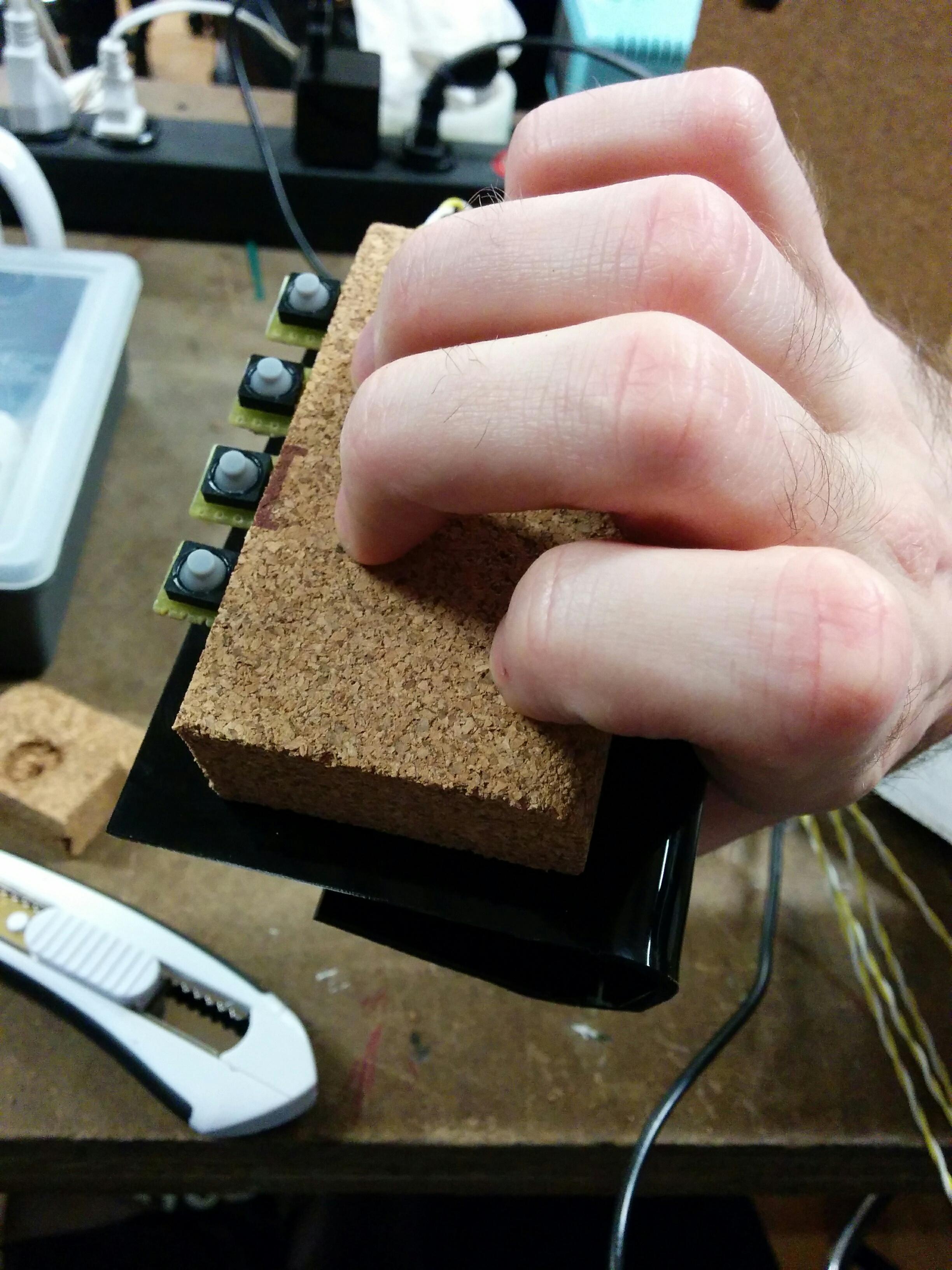
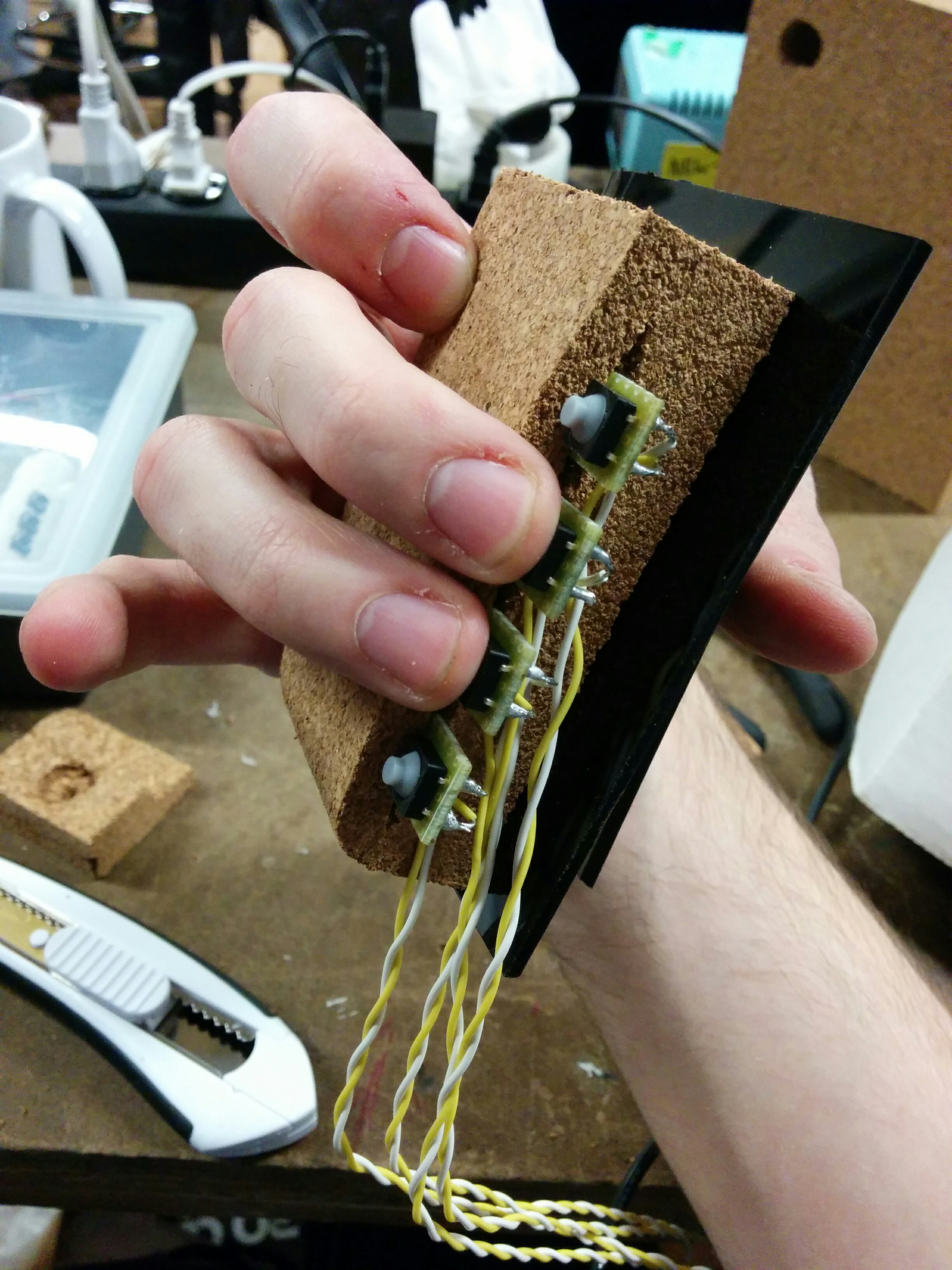
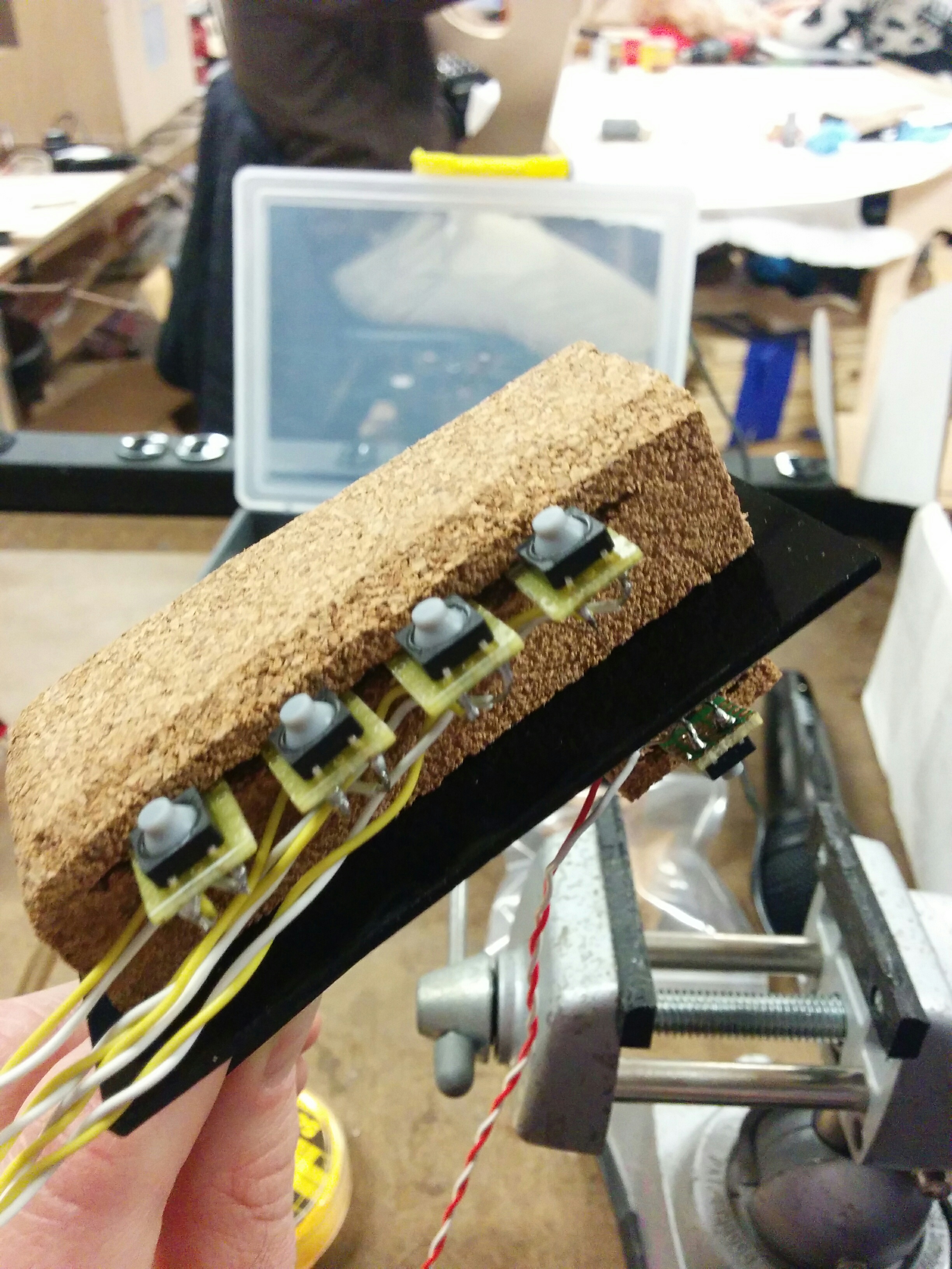
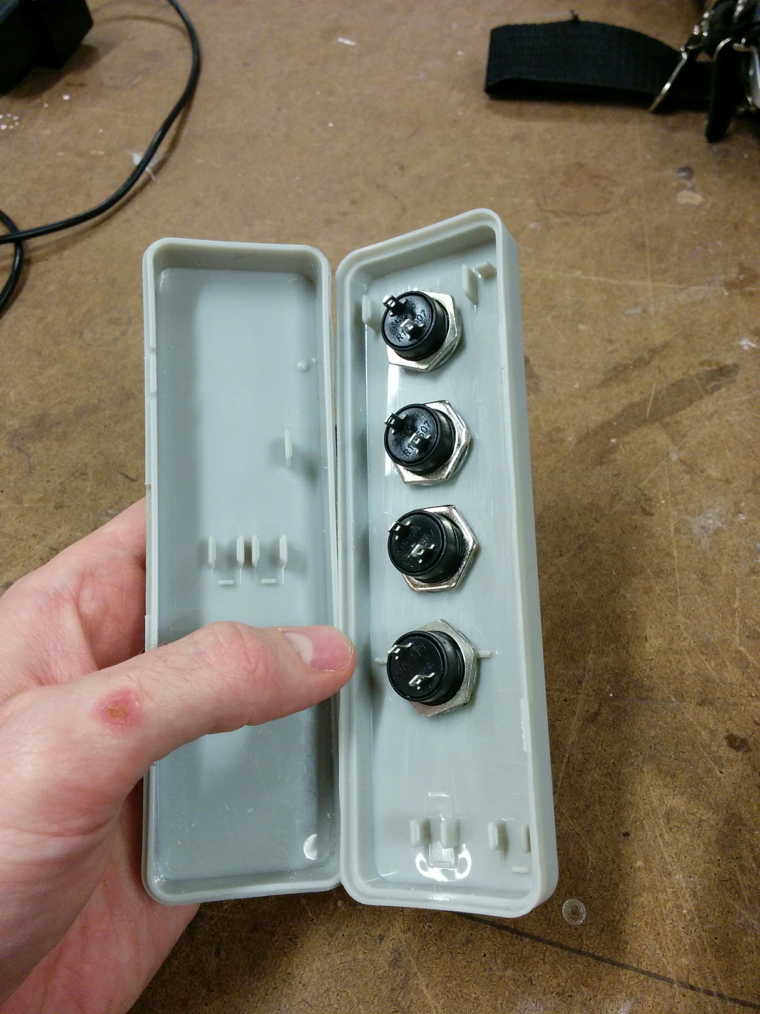
Which is even more apparent when you look at the end result. After trying to keep an even hand, slowly testing the button and returning to the Dremel, then sanding out the end results, some of the holes were looking… interesting.

img_20161118_160001 img_20161118_160005 img_20161118_170112 img_20161118_170129

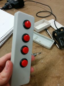
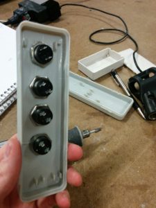
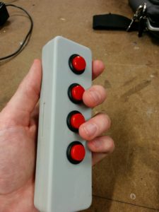
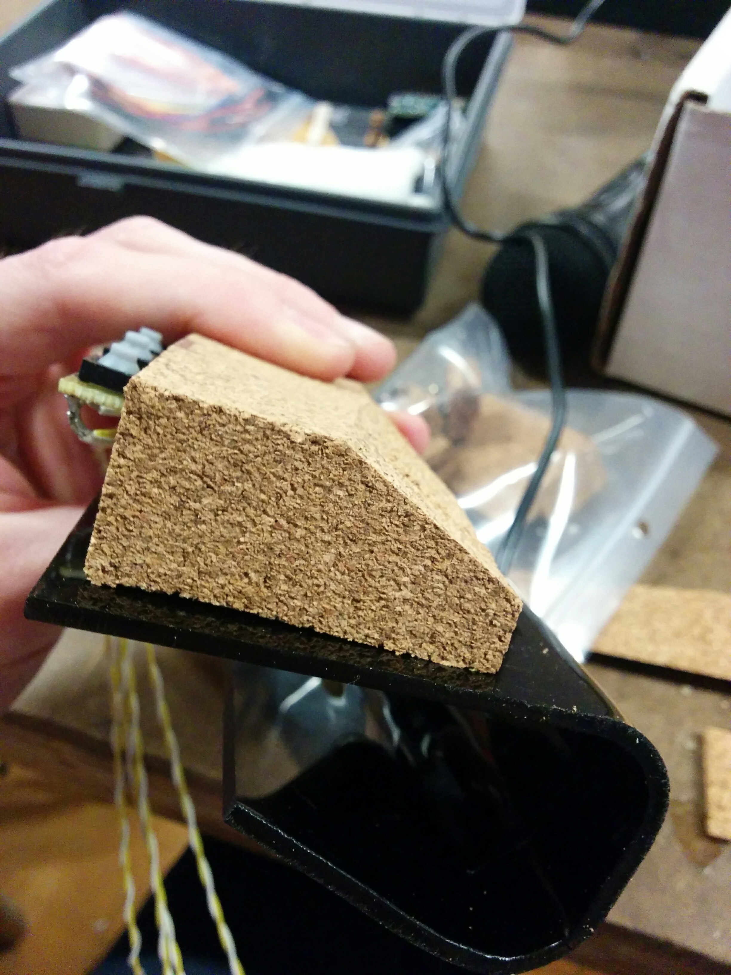
However ugly, they were effective. Constantly testing them made sure that the buttons fit as tightly as possible.img_20161118_170230 img_20161118_170315

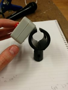
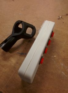
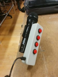
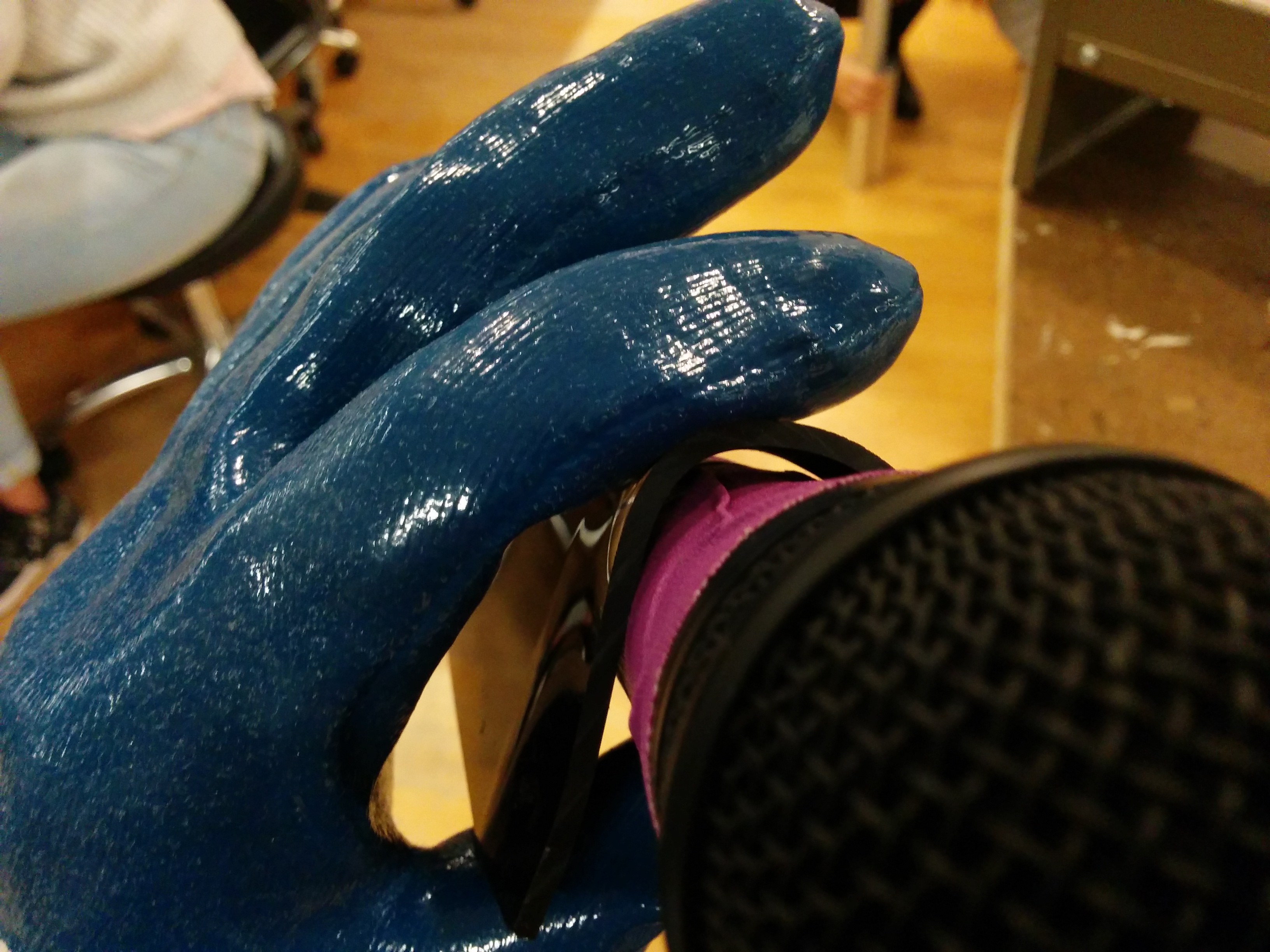
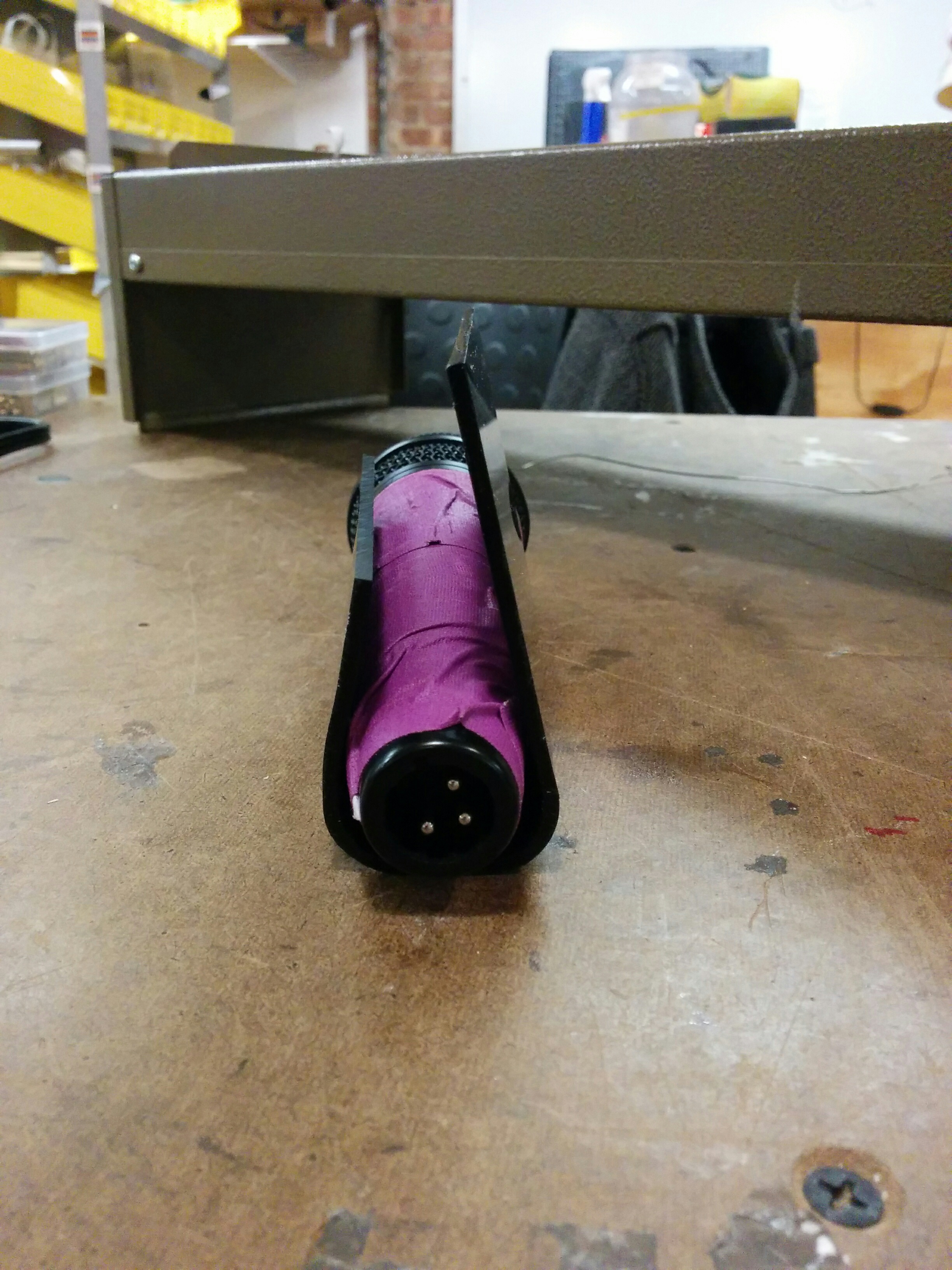
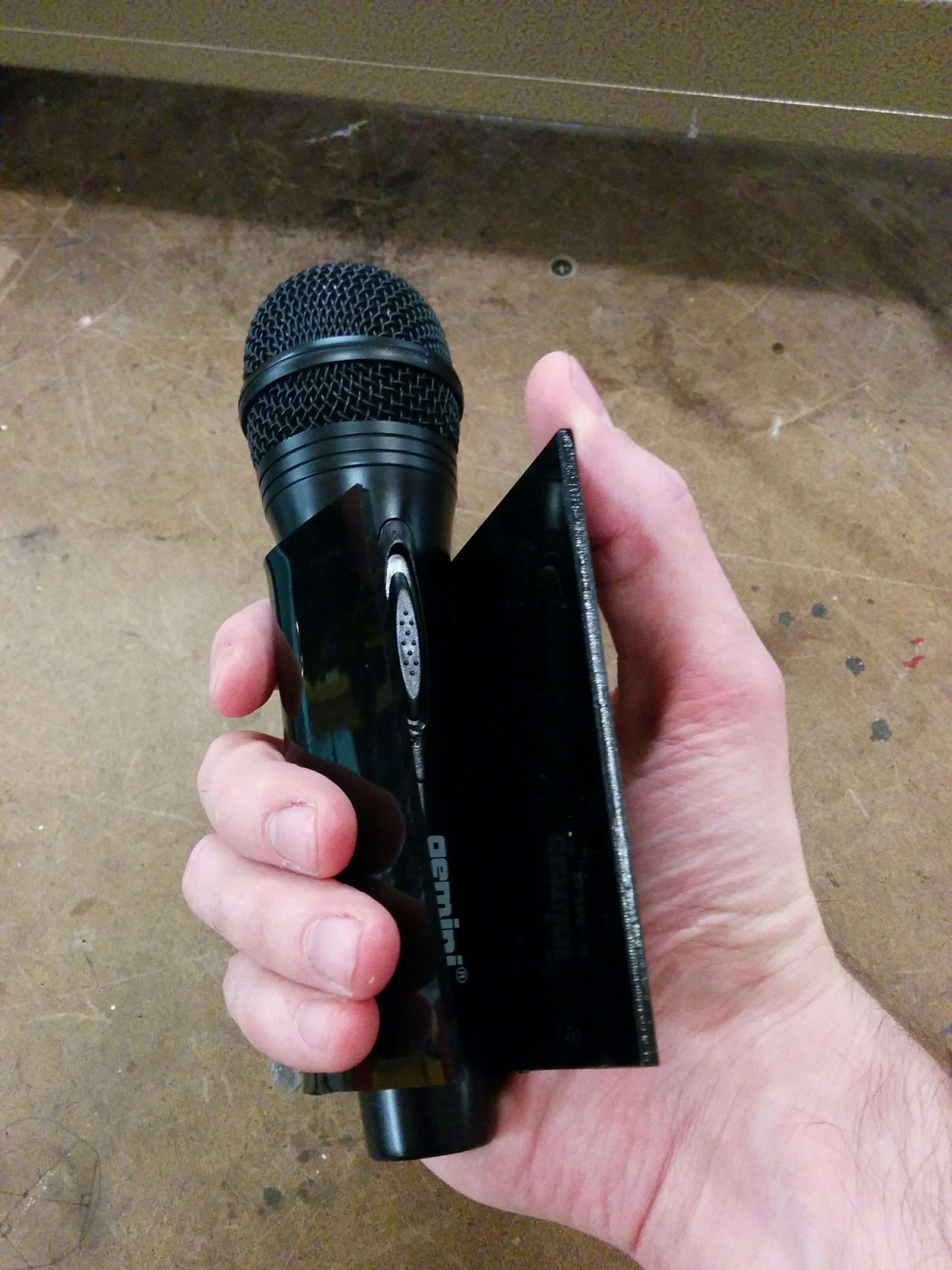
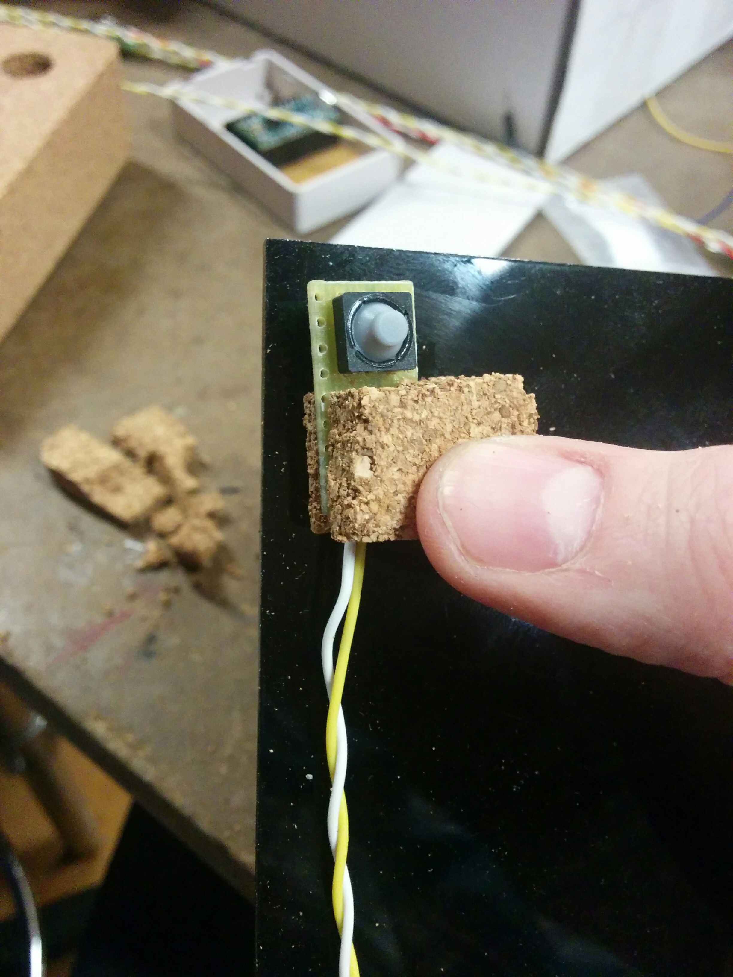
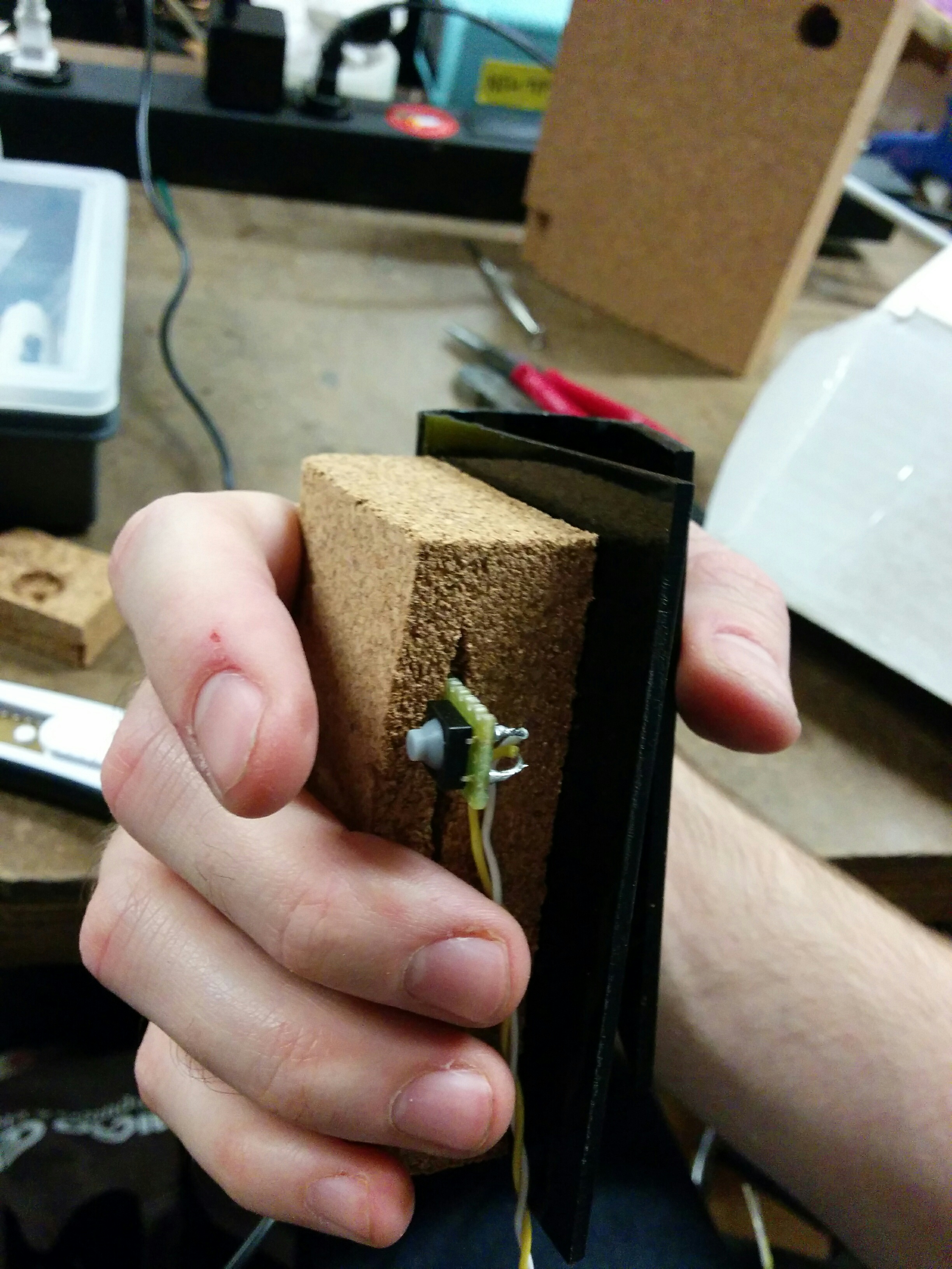
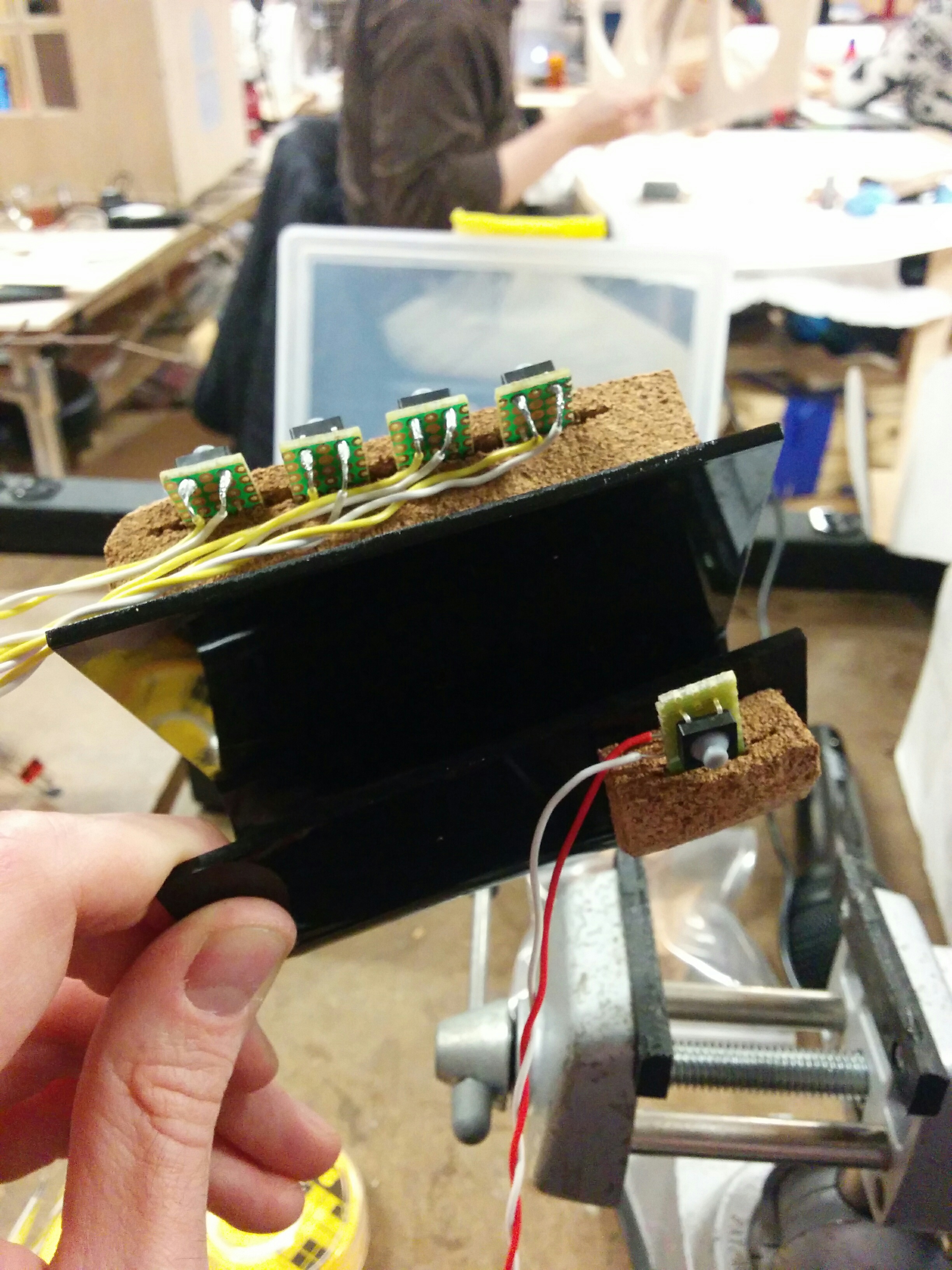
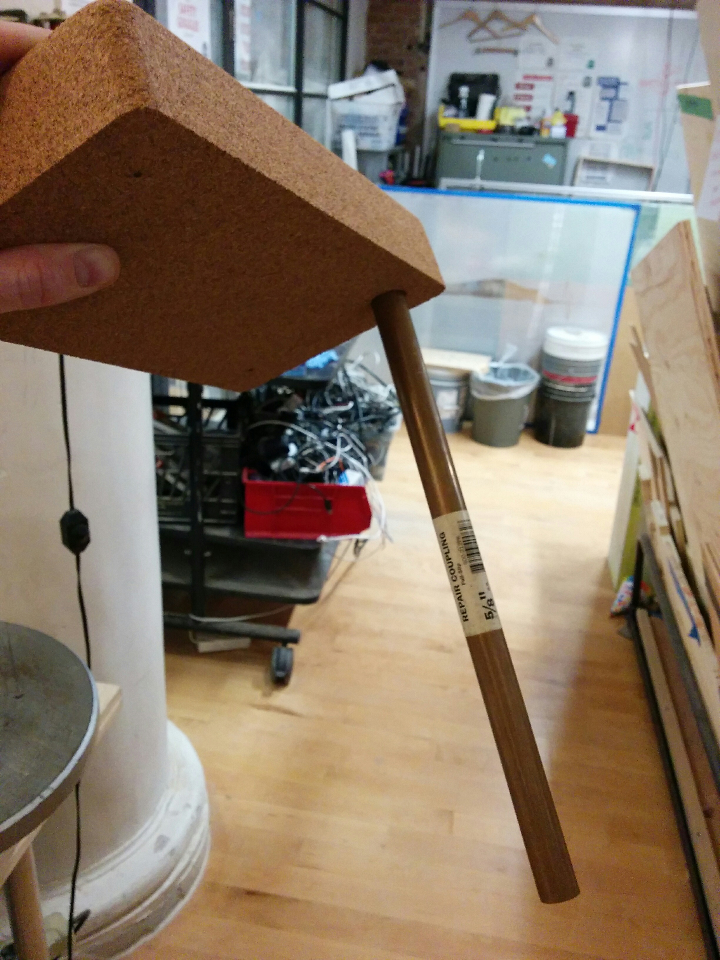
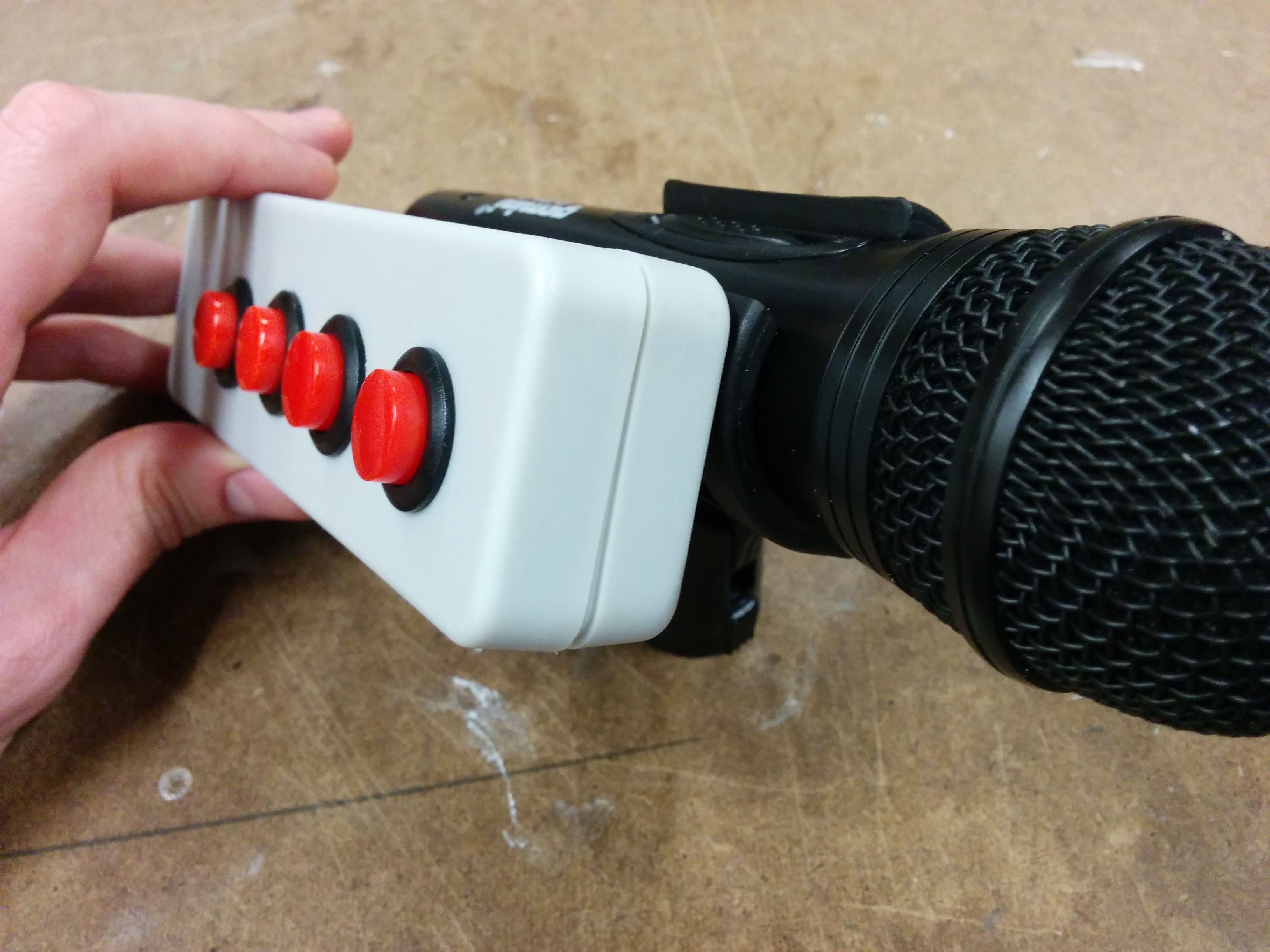
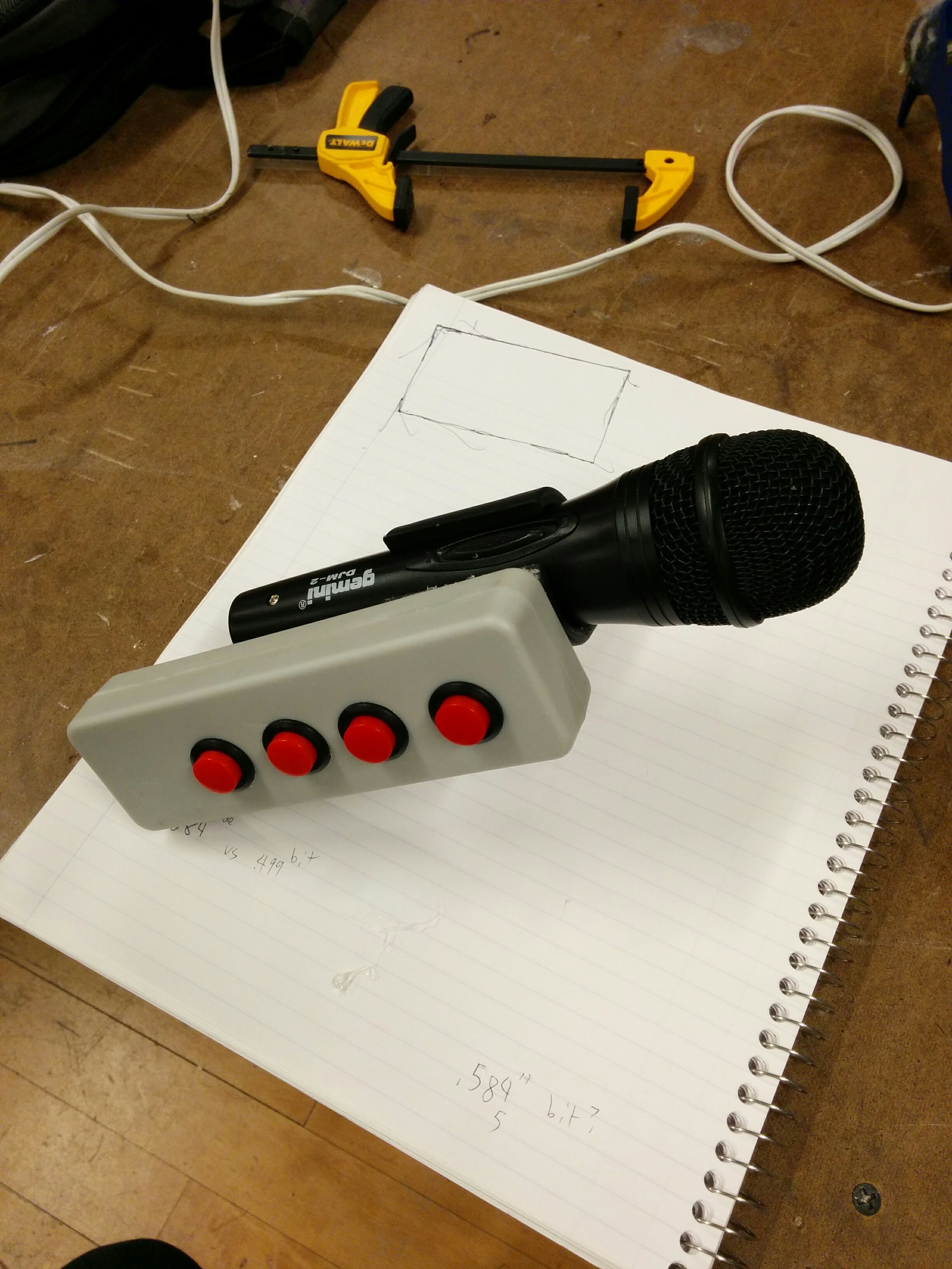
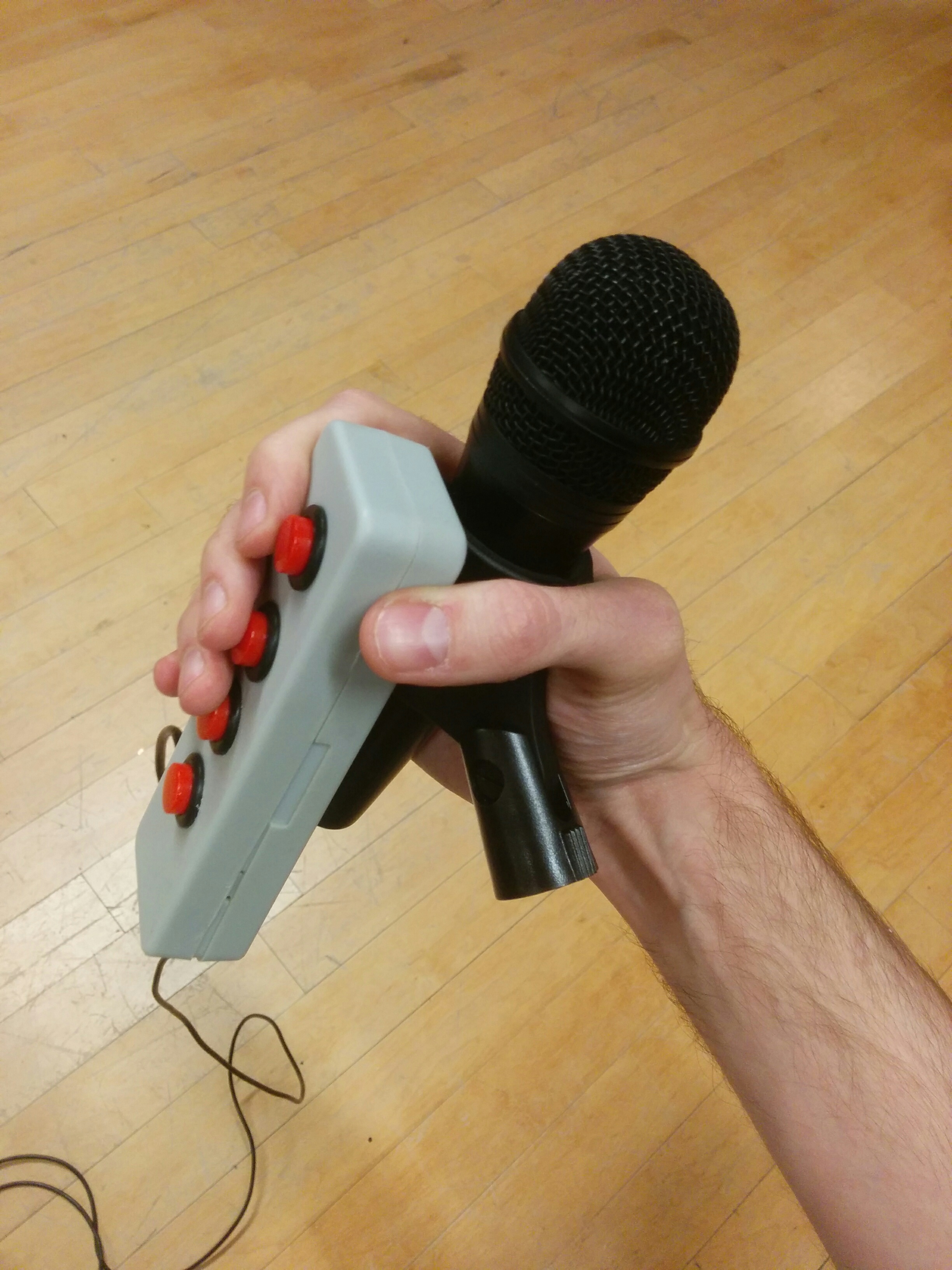
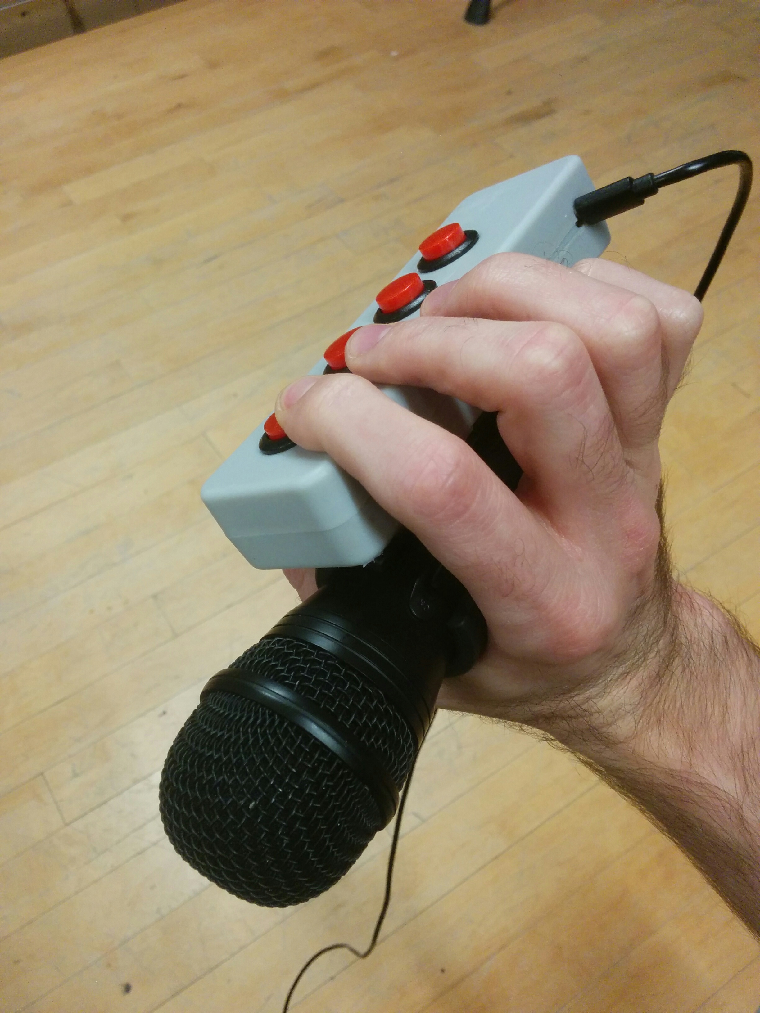
Putting this up against the mic clip, I was happy that I started walking before I ran. Going with a more straightforward box now feels like a wiser choice when considering how things can and will change over my prototyping process. But I wasn’t sure of the best way to properly attach them together. Because of the nature of the clip, which expands as mics are inserted and is tightly flush against the surface of the mic neck, there were many approaches that I would normally take that were off the table.

Not entirely sure where to turn… I went with plain ol’ hot glue.

img_20161118_171806 img_20161118_172337 img_20161118_172917

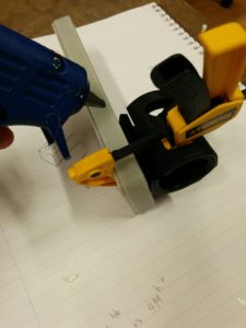
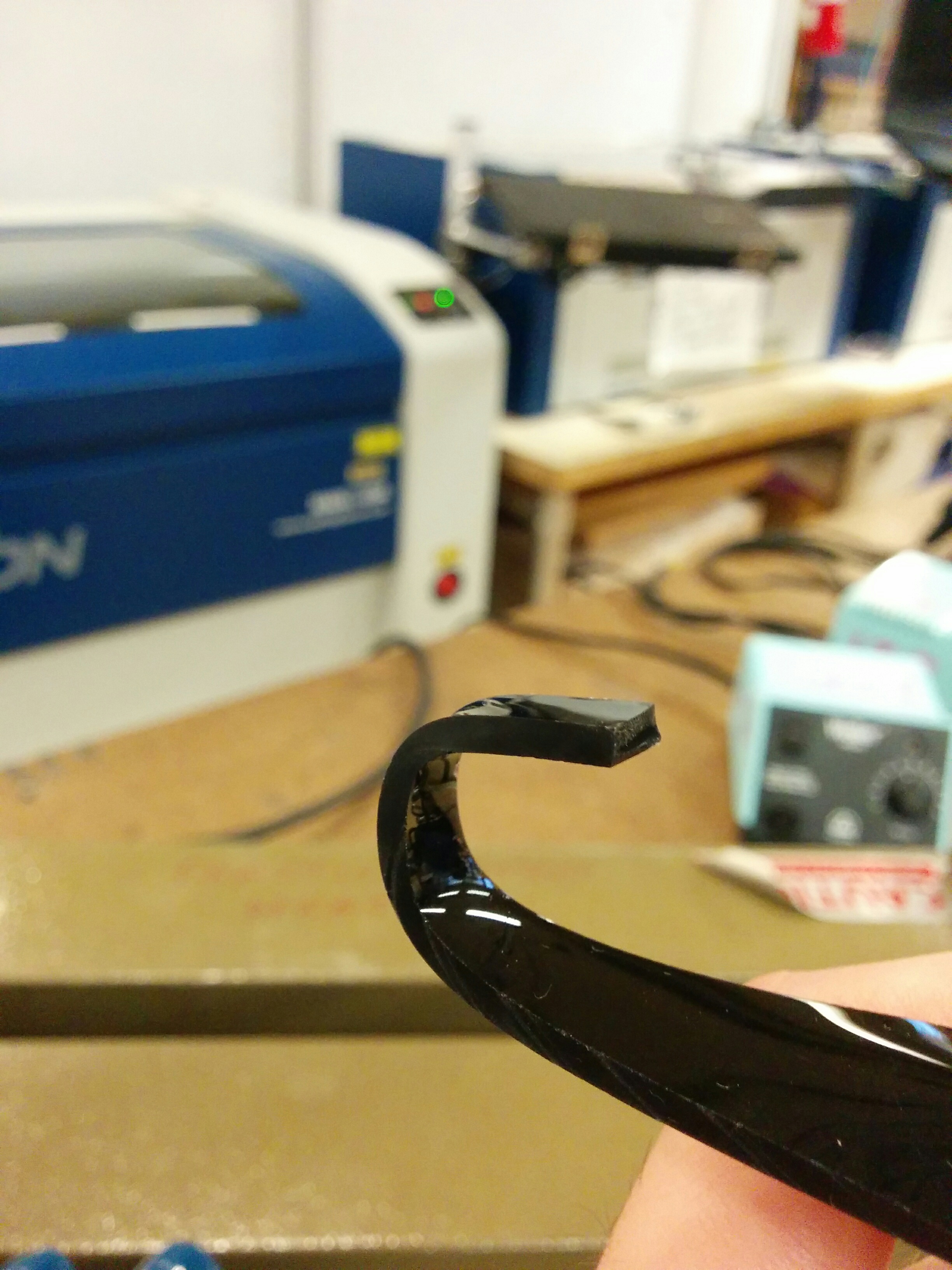
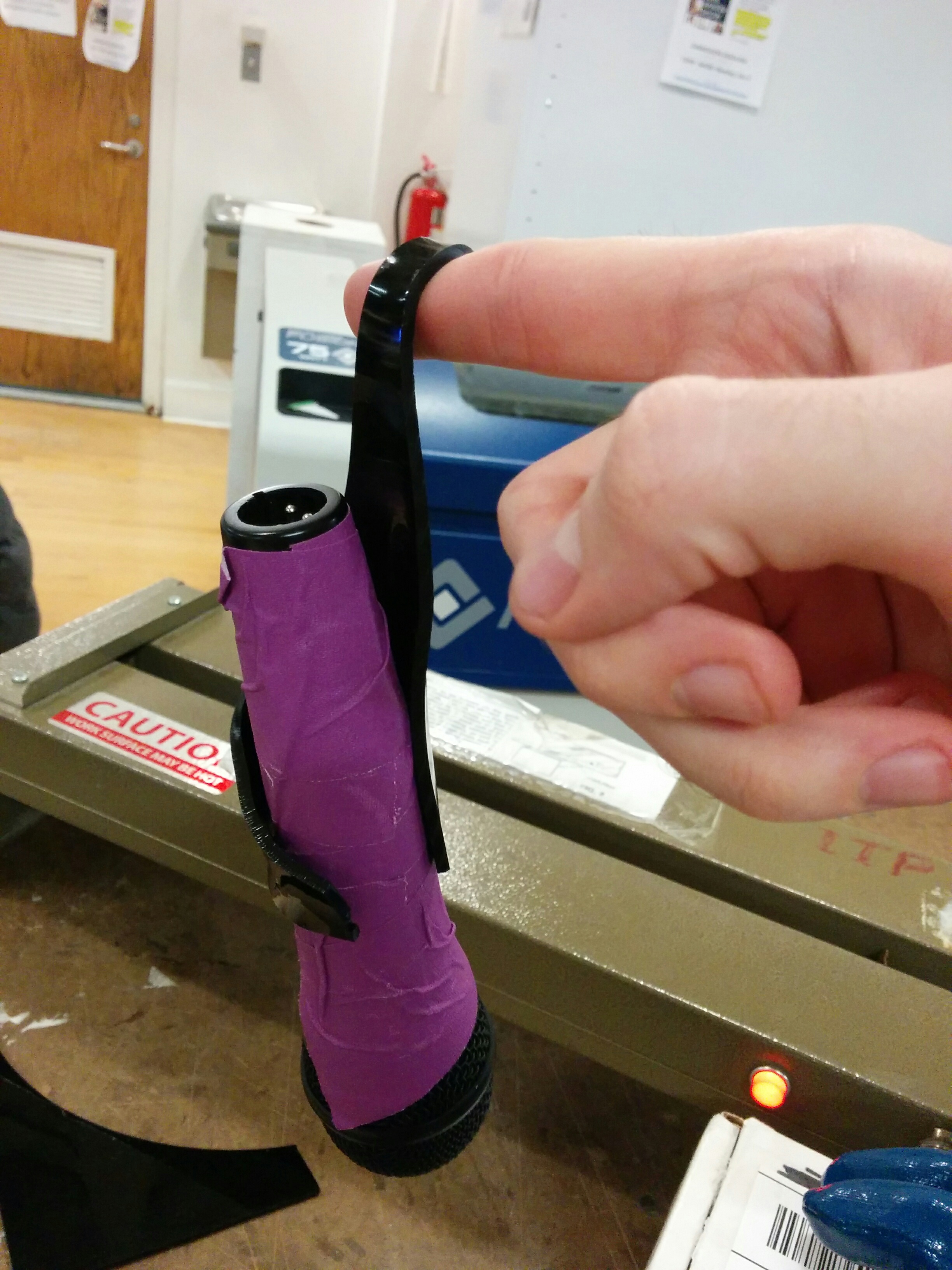
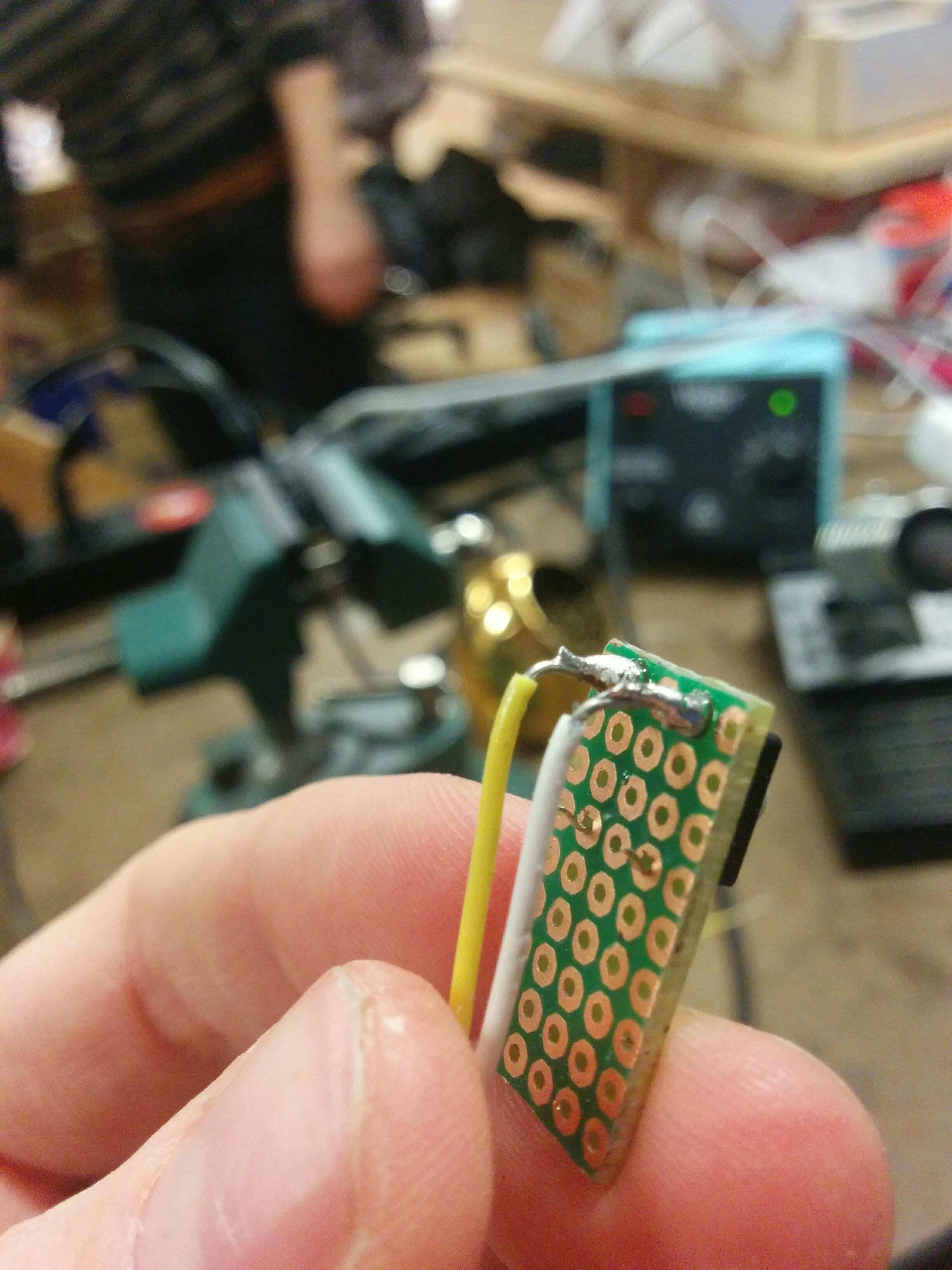
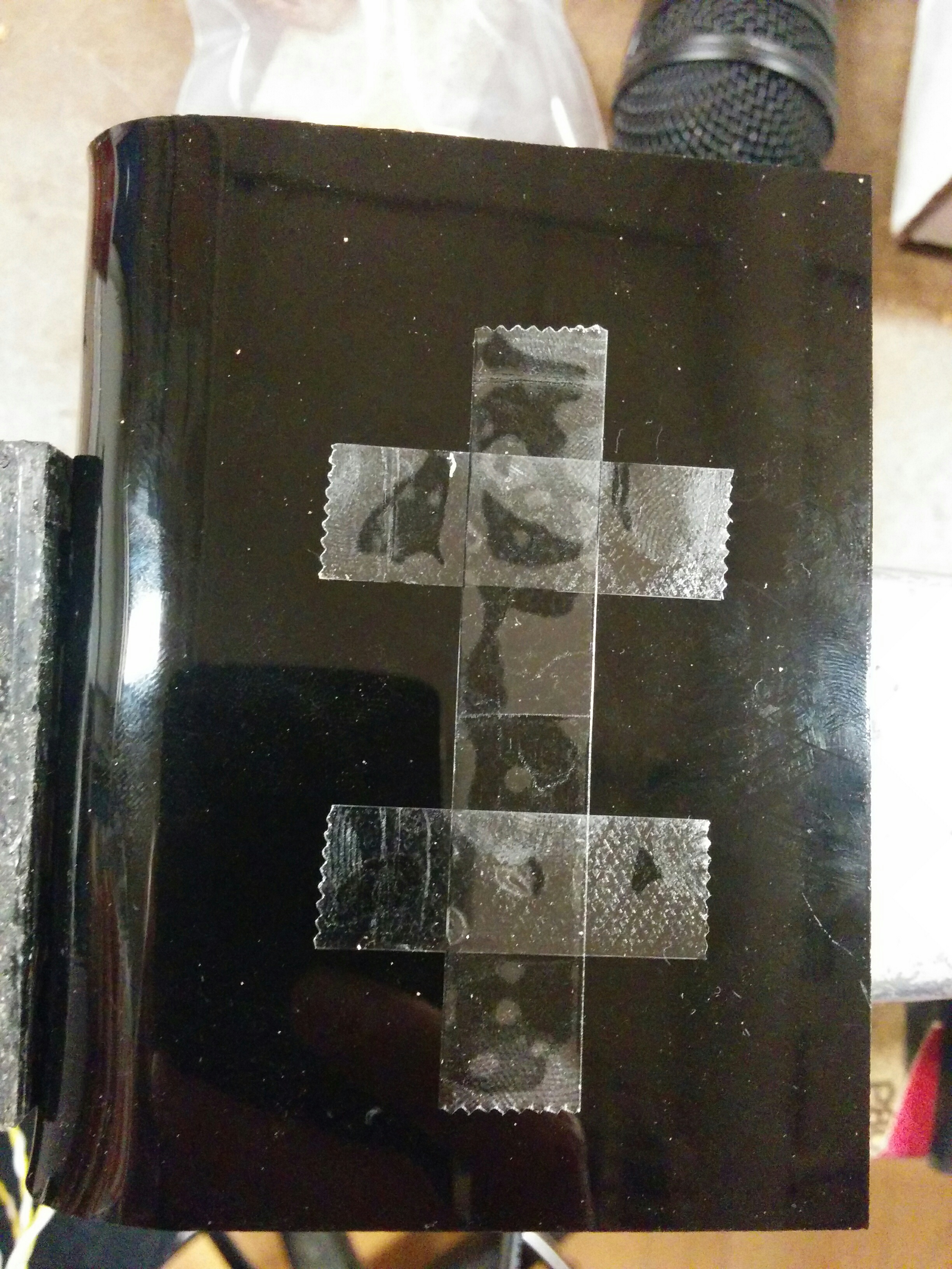
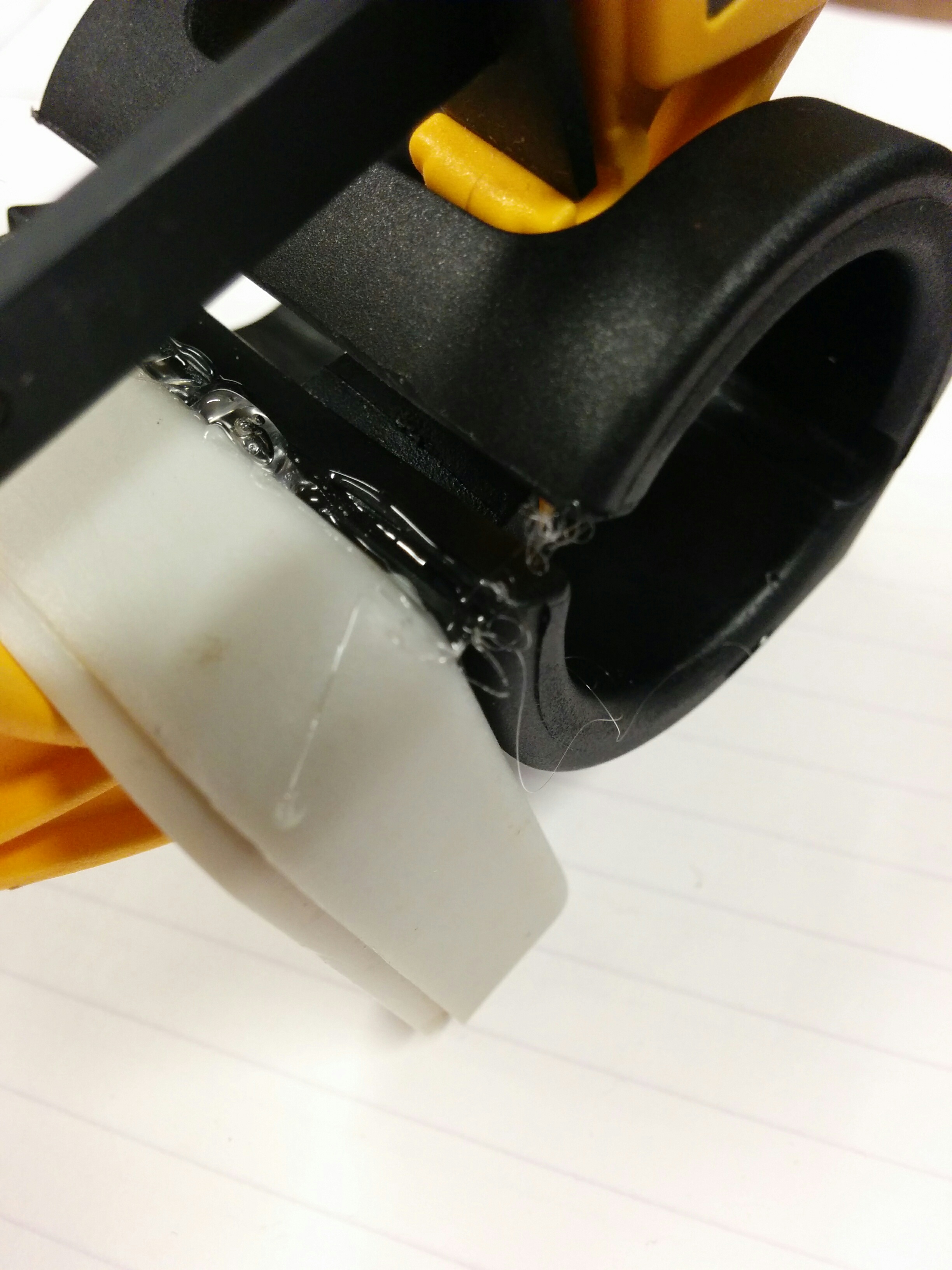
Hot glue. It’s like this totally normal thing that people use all the time, right? Wow can it get messy quick. One day I would like to get some tutoring on elegant hot glue technique (if such a thing exists). Luckily, it was easy enough to pull away the fine strands and peel off the egregious errors where necessary. I wound up with somewhat of a loose hinge:

img_20161118_173014img_20161118_173136

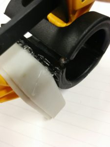
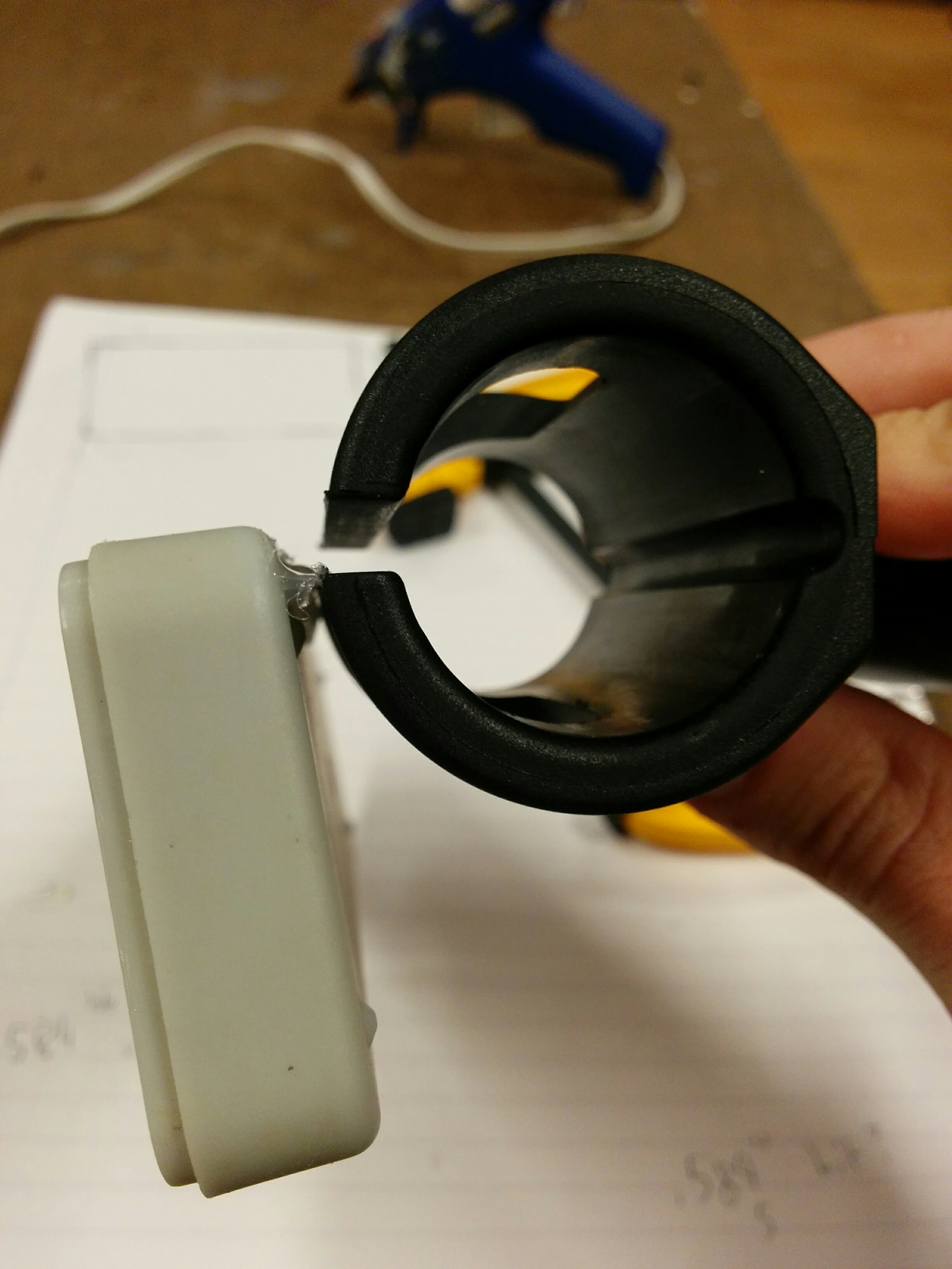
Then with that I was able to do a second round that covered more surface area and adhered solidly.

img_20161118_173422img_20161118_173757img_20161118_173844

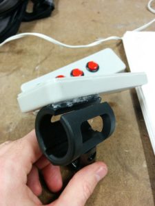
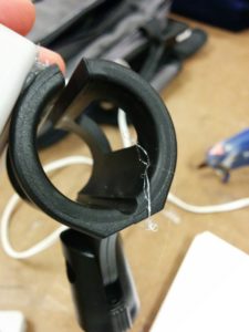
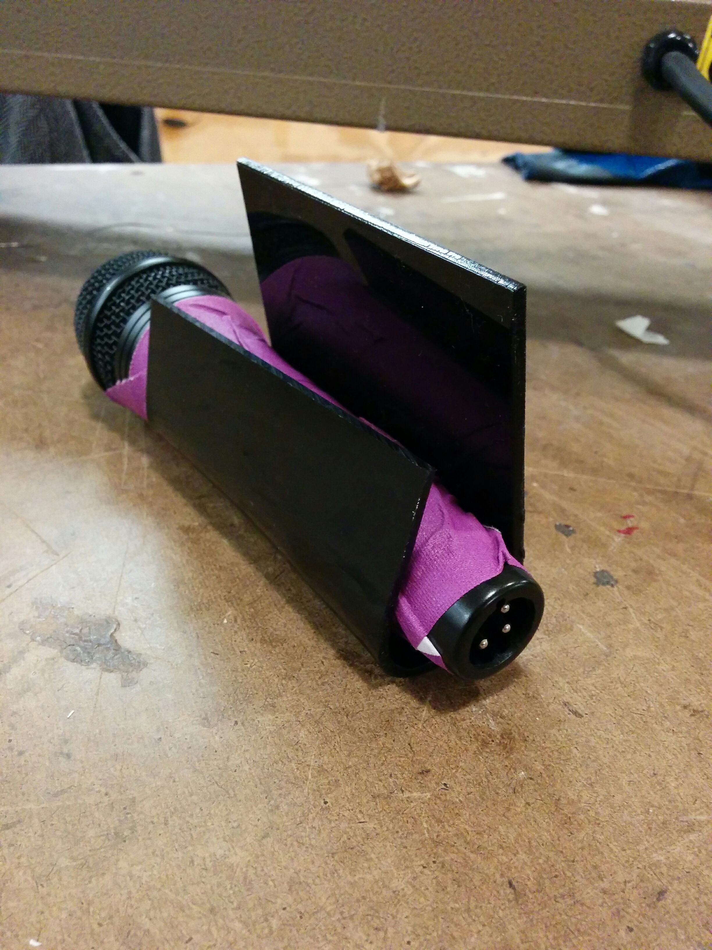
Yeesh! These glue strands get everywhere. But after some cleaning up I wound up with something fairly sturdy:

img_20161118_173555 img_20161118_173610 img_20161118_173619

That is where I’ve left off for now. I have some parts coming in, and depending on specifics might change the focus of the rest of this assignment. It could make sense to just keep it more or less looking the way it is and hook it up to my microcontroller once I get all the parts, and keep this as a version 1.0 functional prototype. However, despite it’s early 80’s beige/gray charm, there is a part of me that would like to make this look a bit more presentable. Updates will soon follow.

Part 2

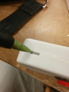
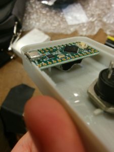
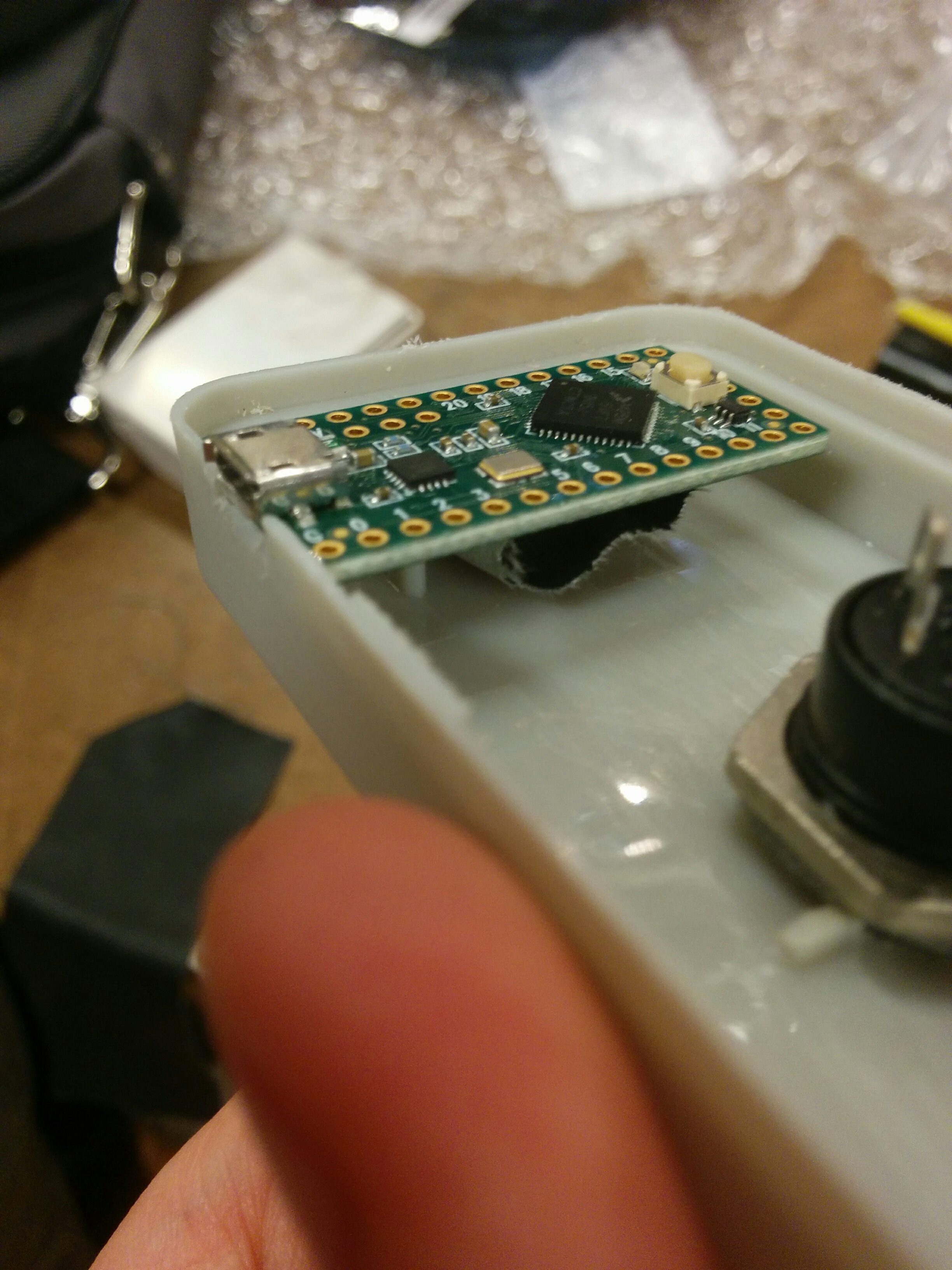
Having some issues uploading my images, but I will do so as soon as my internet connection gets a little better. In the meantime, I have added a little slot for my microcontroller to sit inside of the enclosure. There were some other issues, but I’ve got some decent end results to share. More updates tonight and tomorrow!

The first dissapointment I had upon returning to my project was that the hot glue did not hold. Not sure if this was due to being bumped (it was in my open project box), or otherwise.

img_20161122_131716

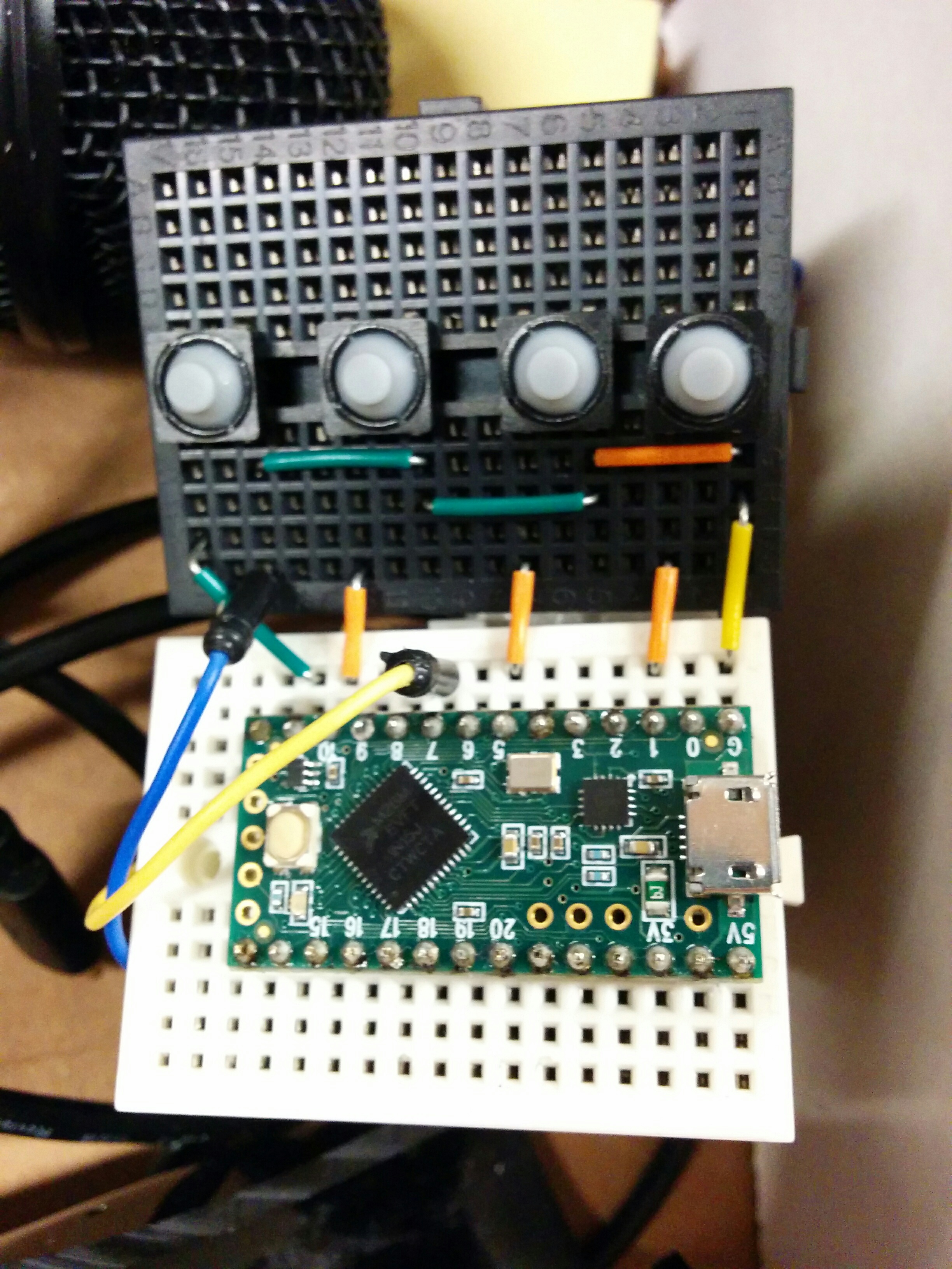
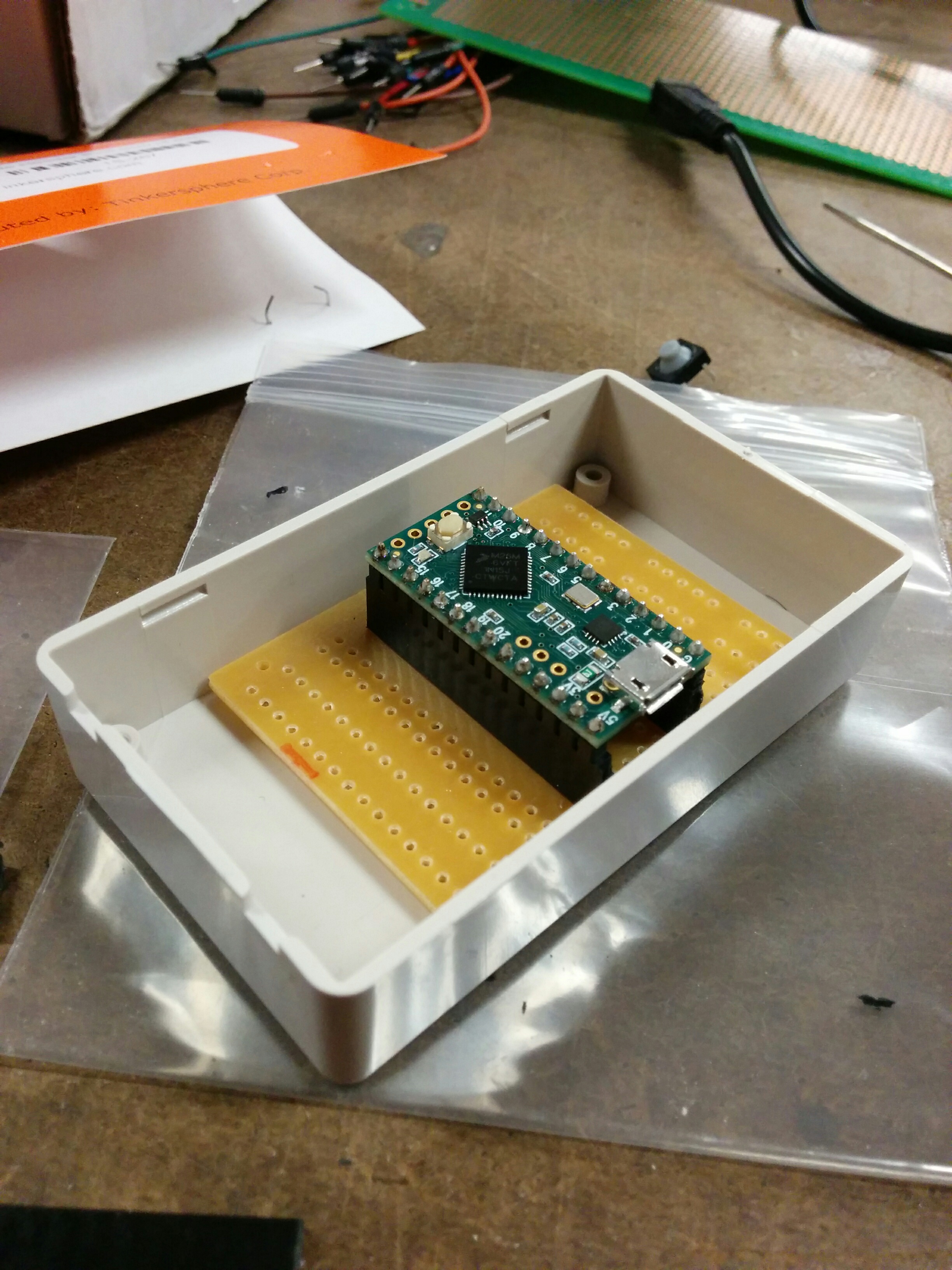
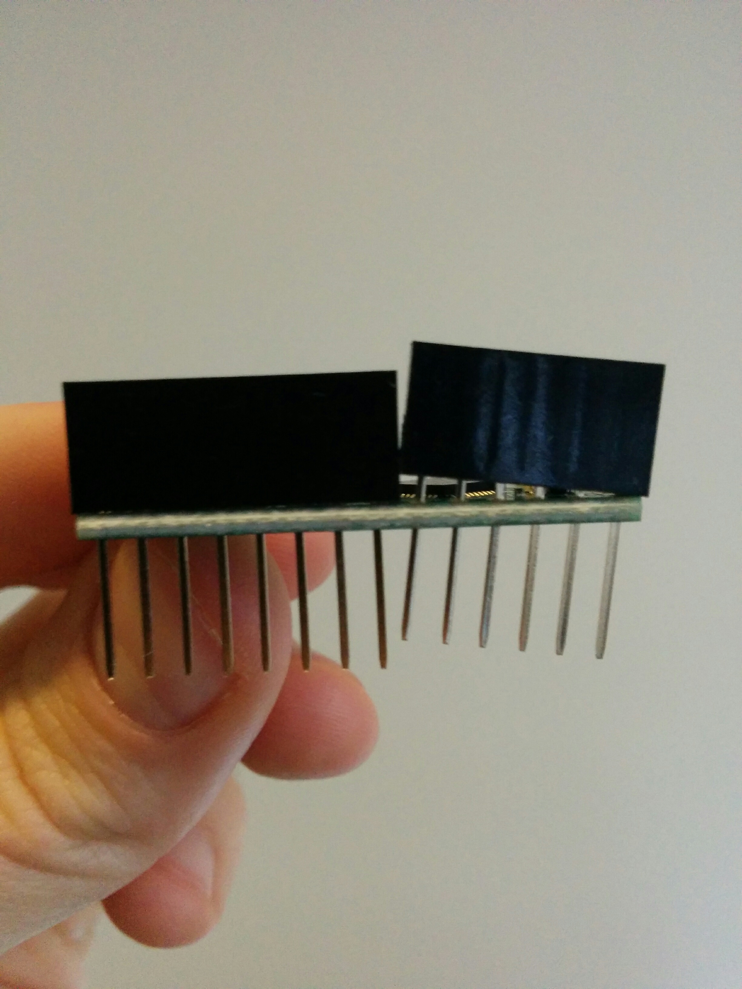
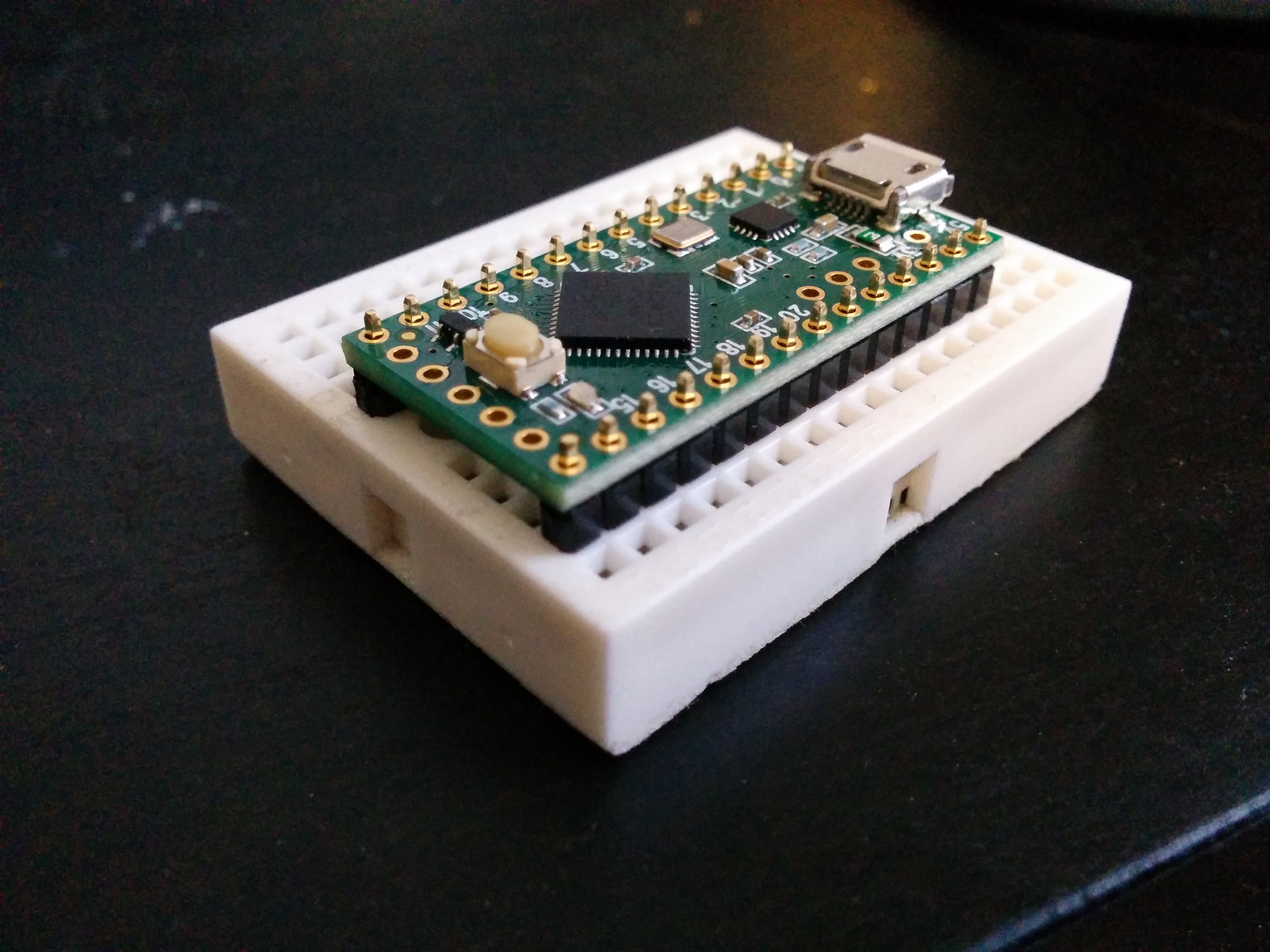
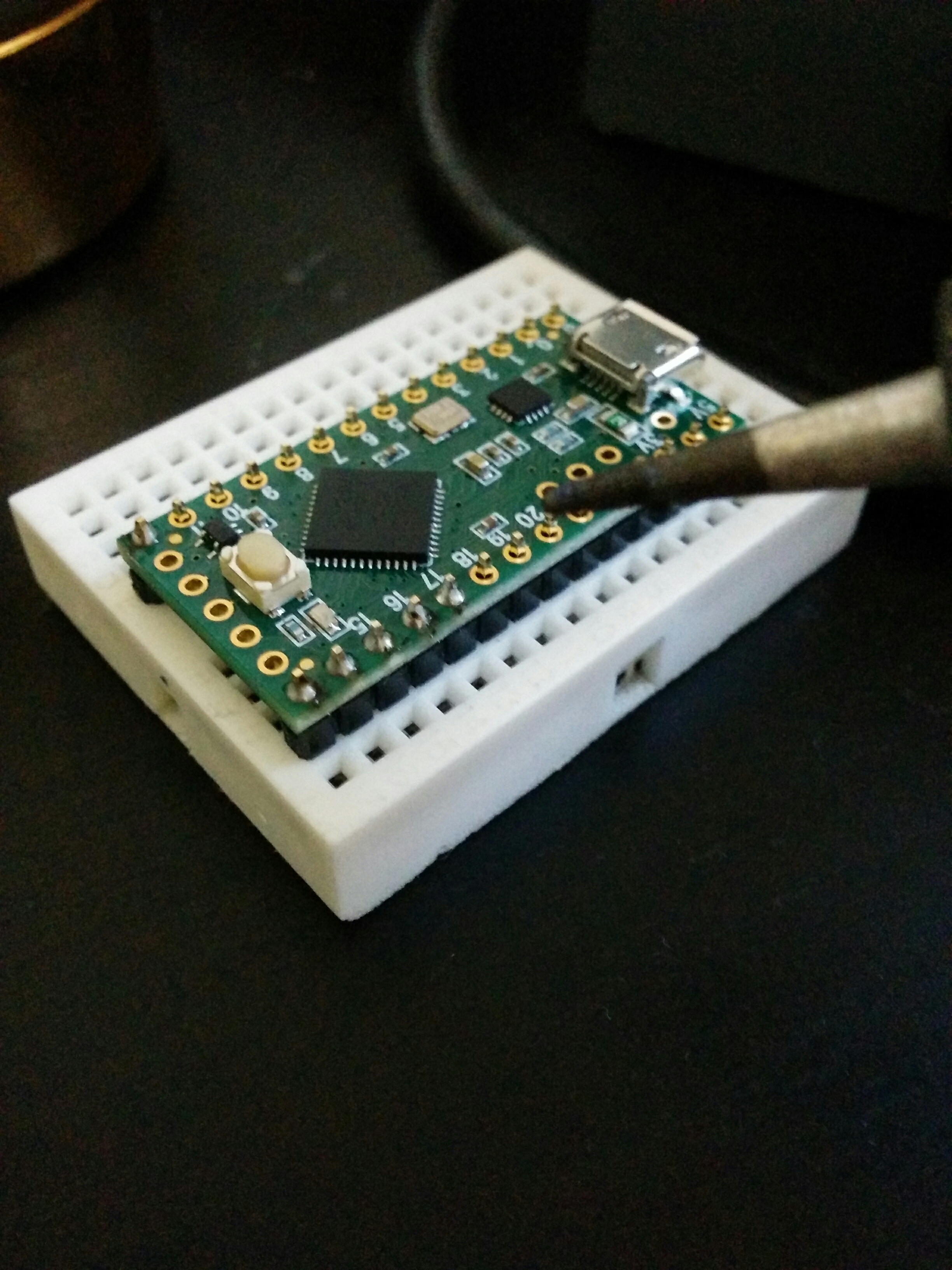
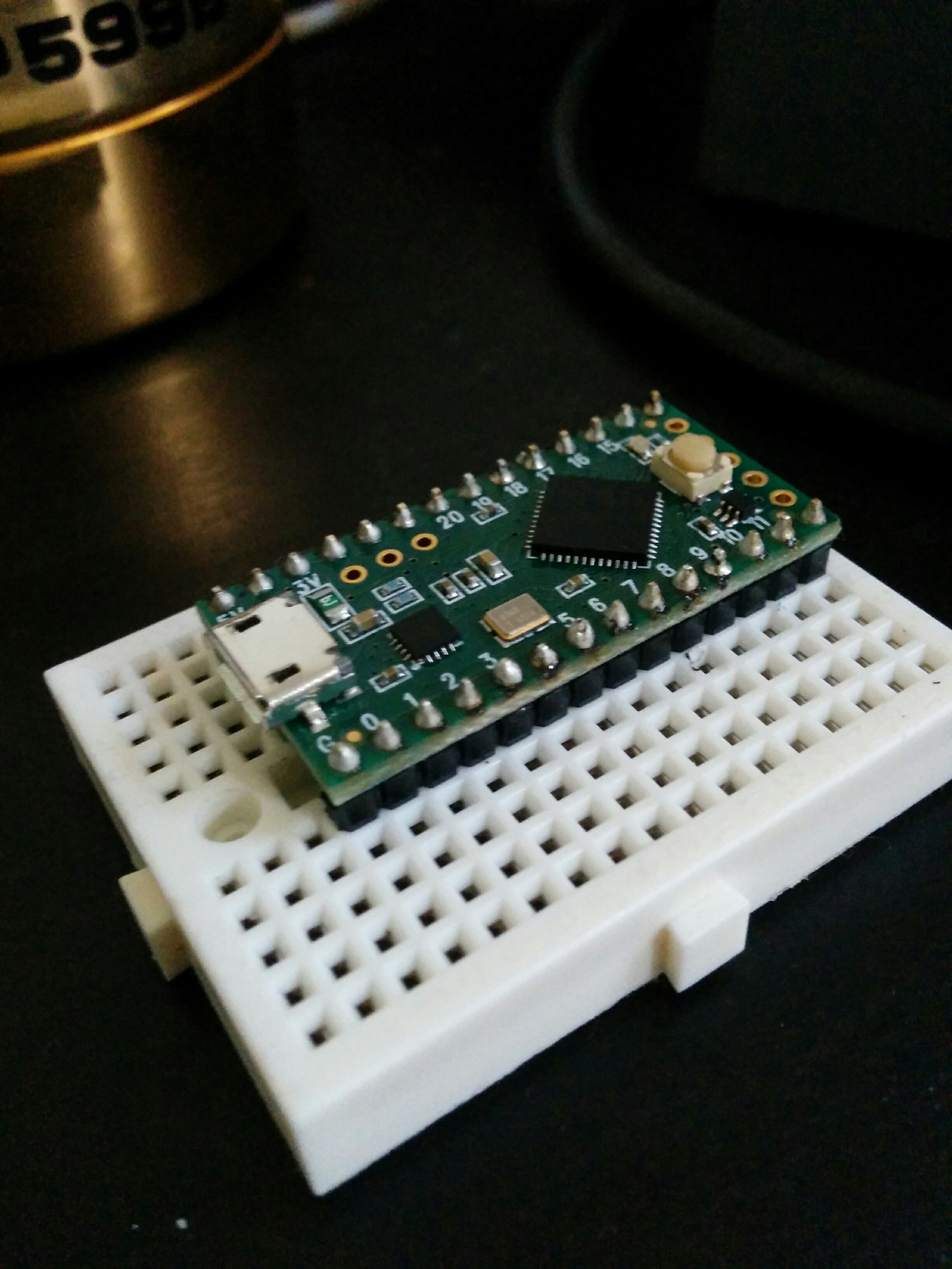
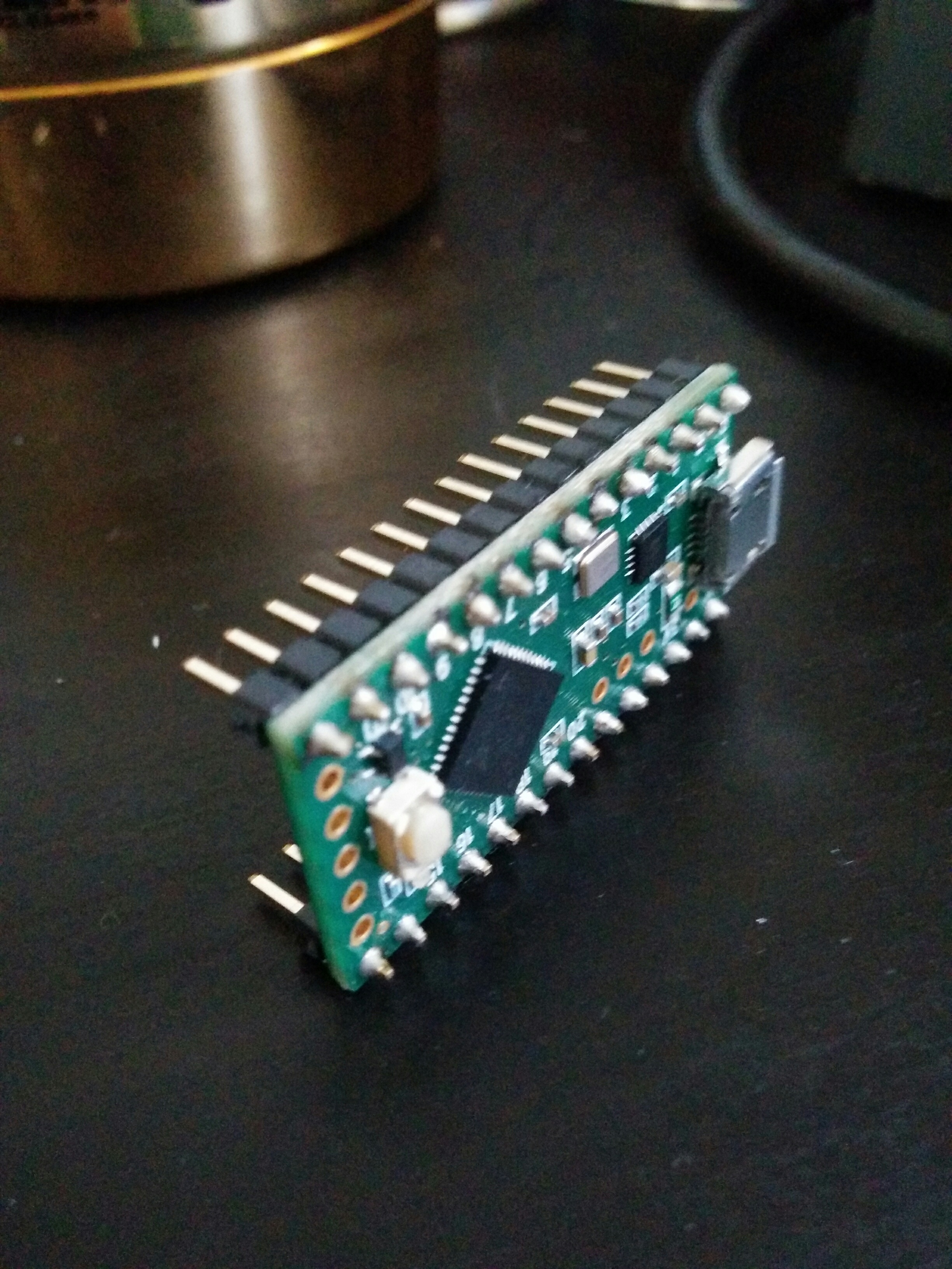
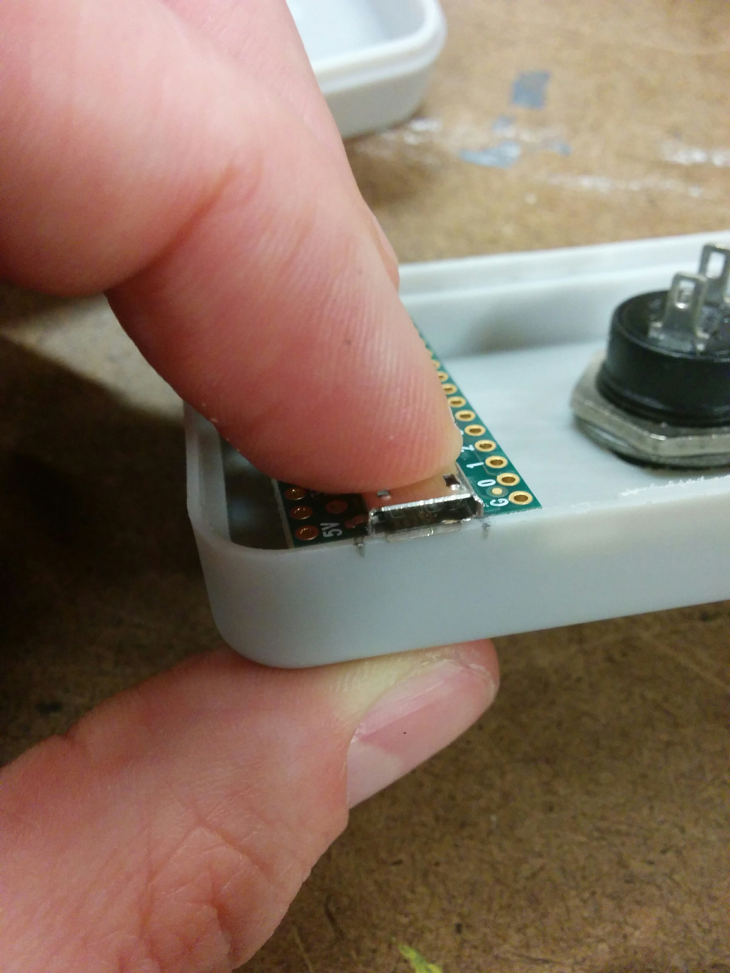
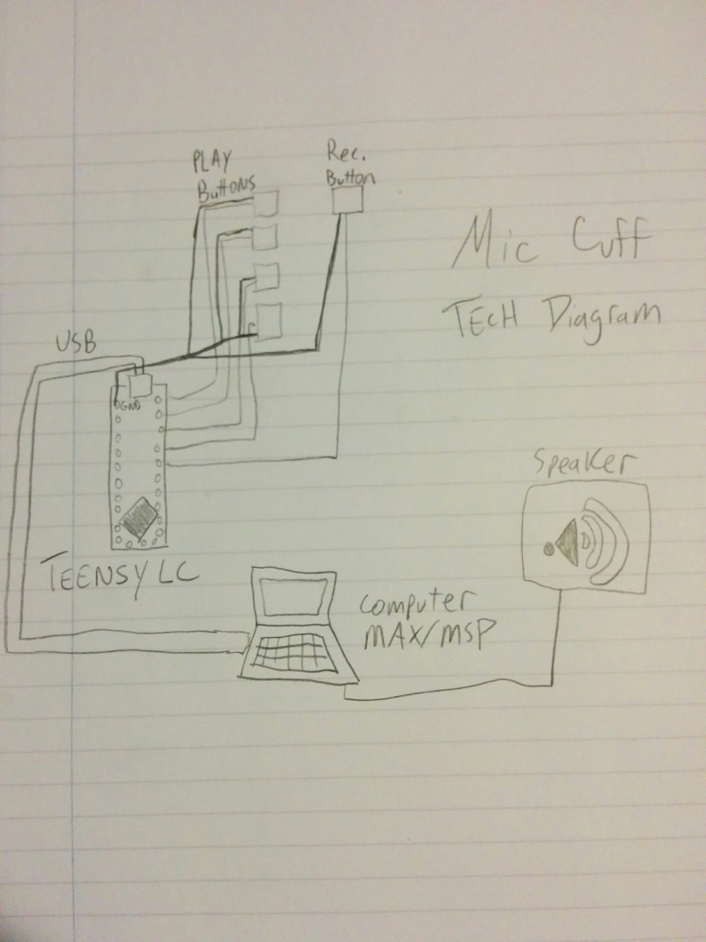
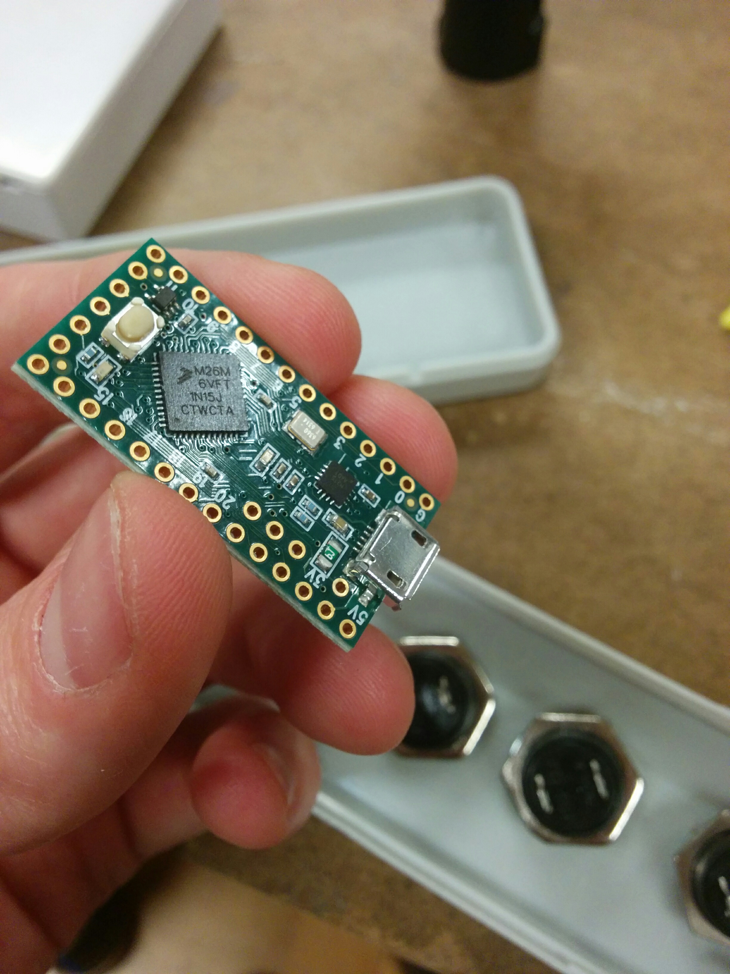
But it was an opportunity to make the work a little easier to handle. I received the microcrontroller I need for my Physical Computing class, the Teensy LC.

img_20161122_141502

But there are no mounting holes on the board! I hadn’t accounted for this when I originally ordered, but it removed the option of using standoffs as a mounting solution.

img_20161122_132226 img_20161122_132452

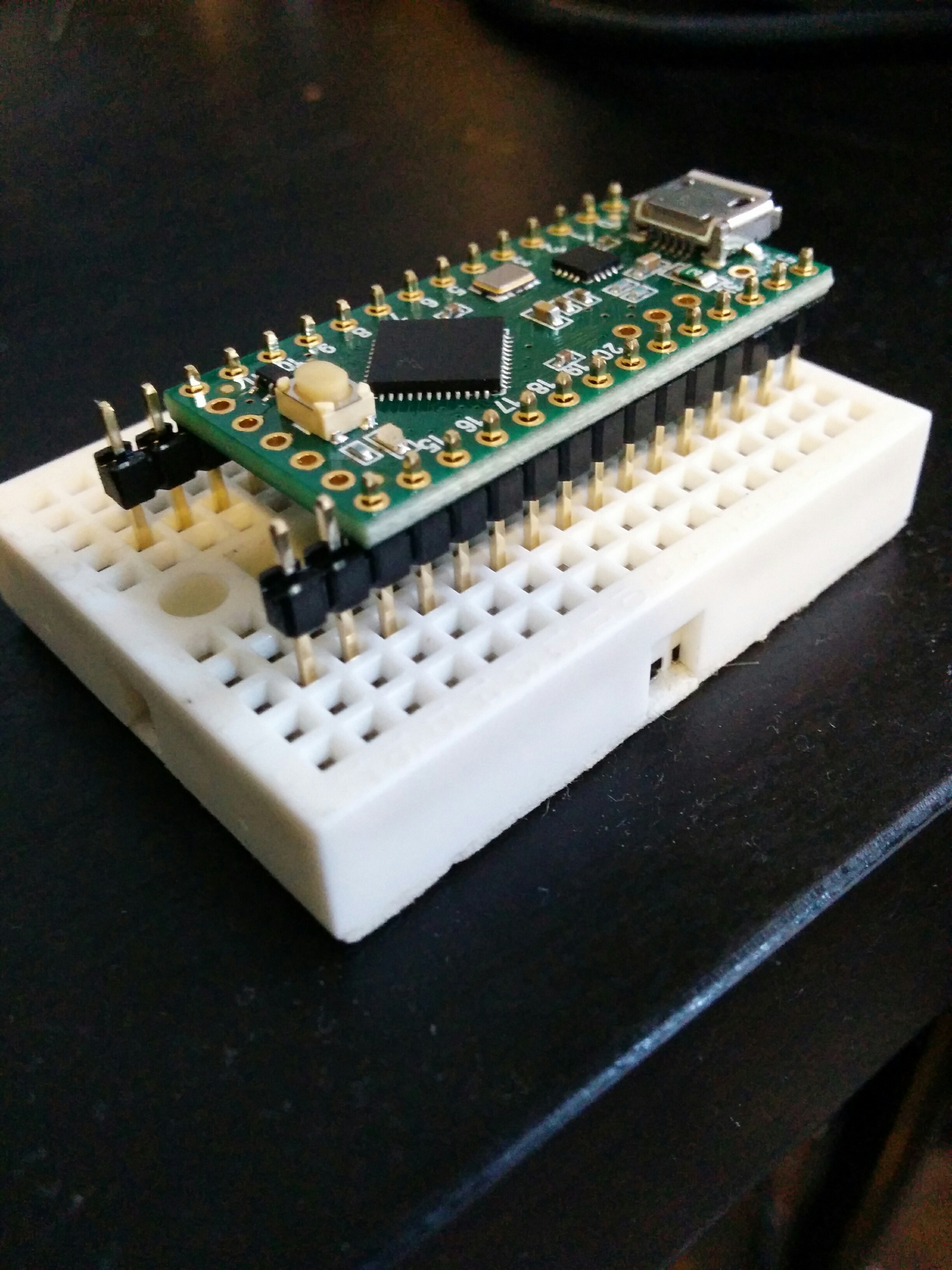
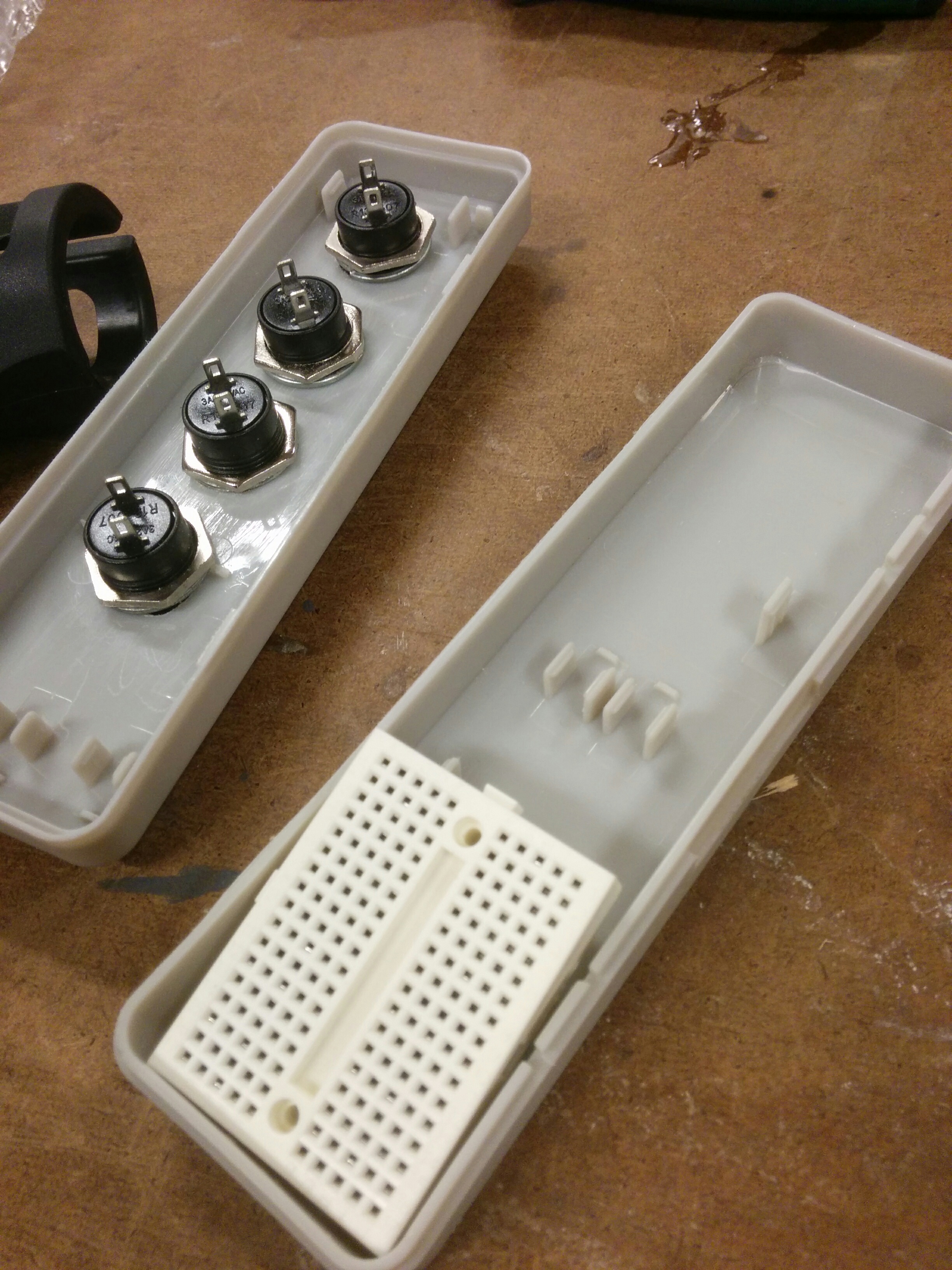
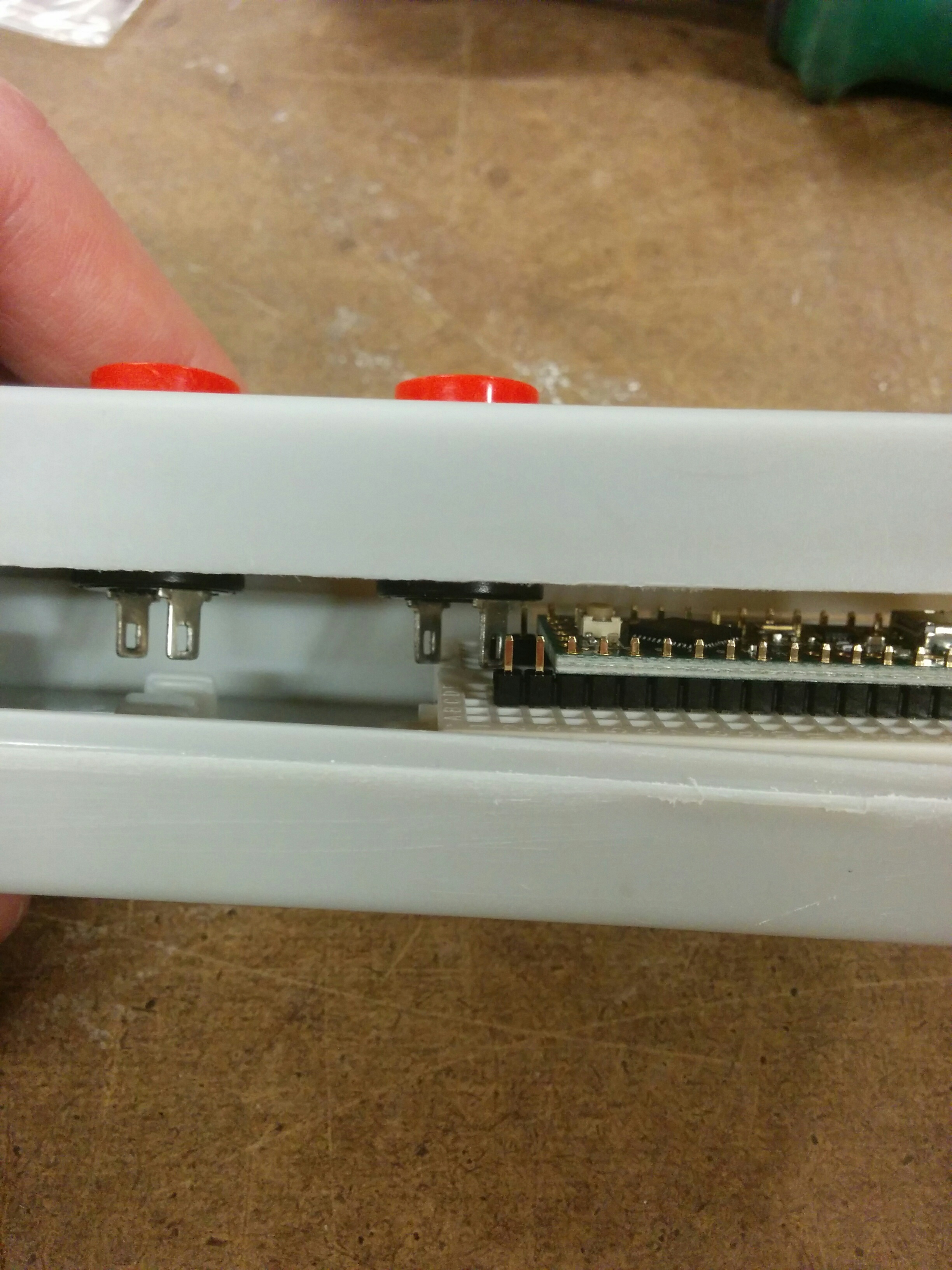
I started clearing out space in the enclosure in order to hold a bread board, which fit *just* perfectly…

img_20161122_134450img_20161122_134415

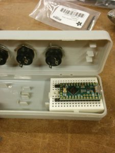
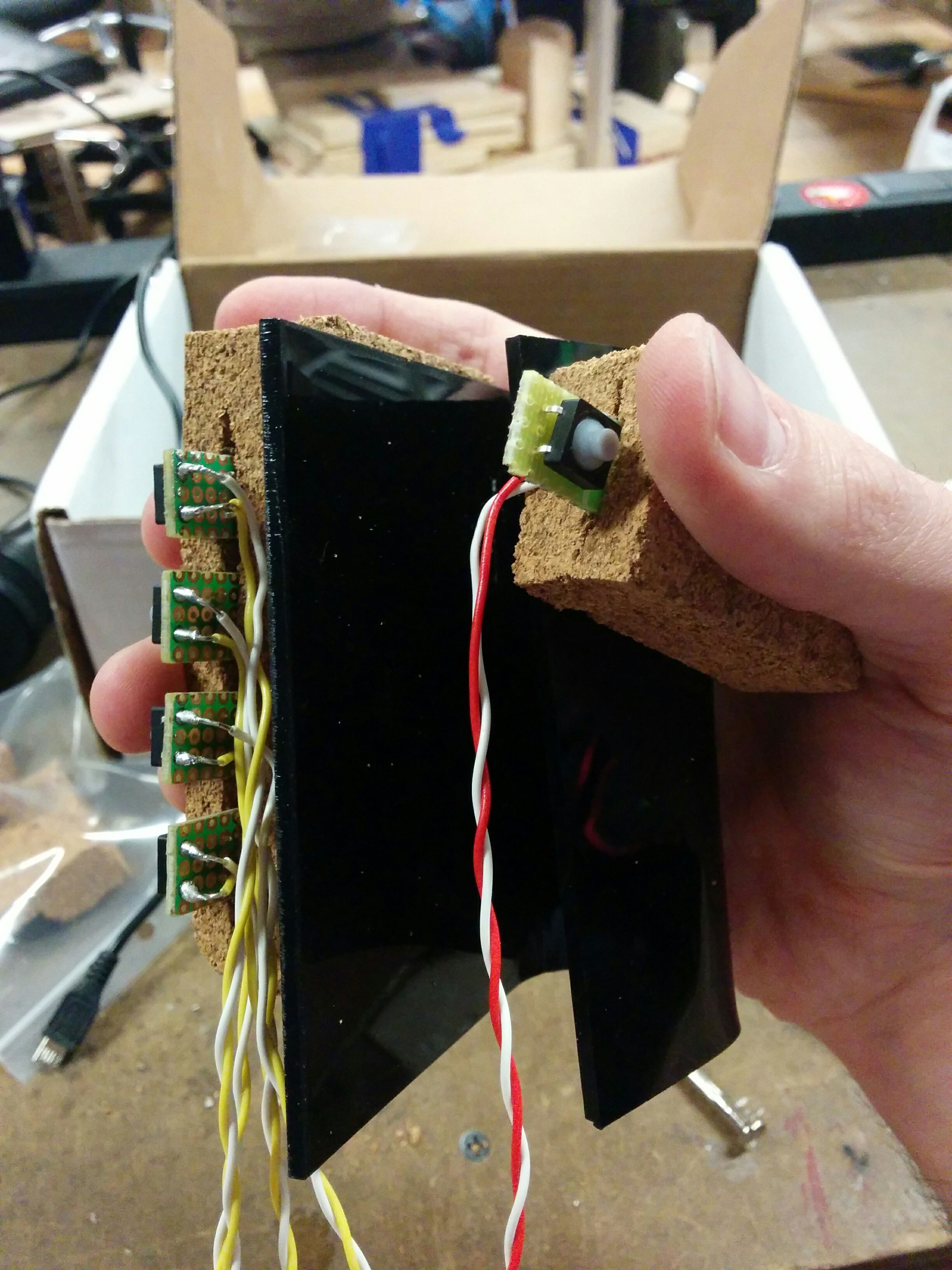
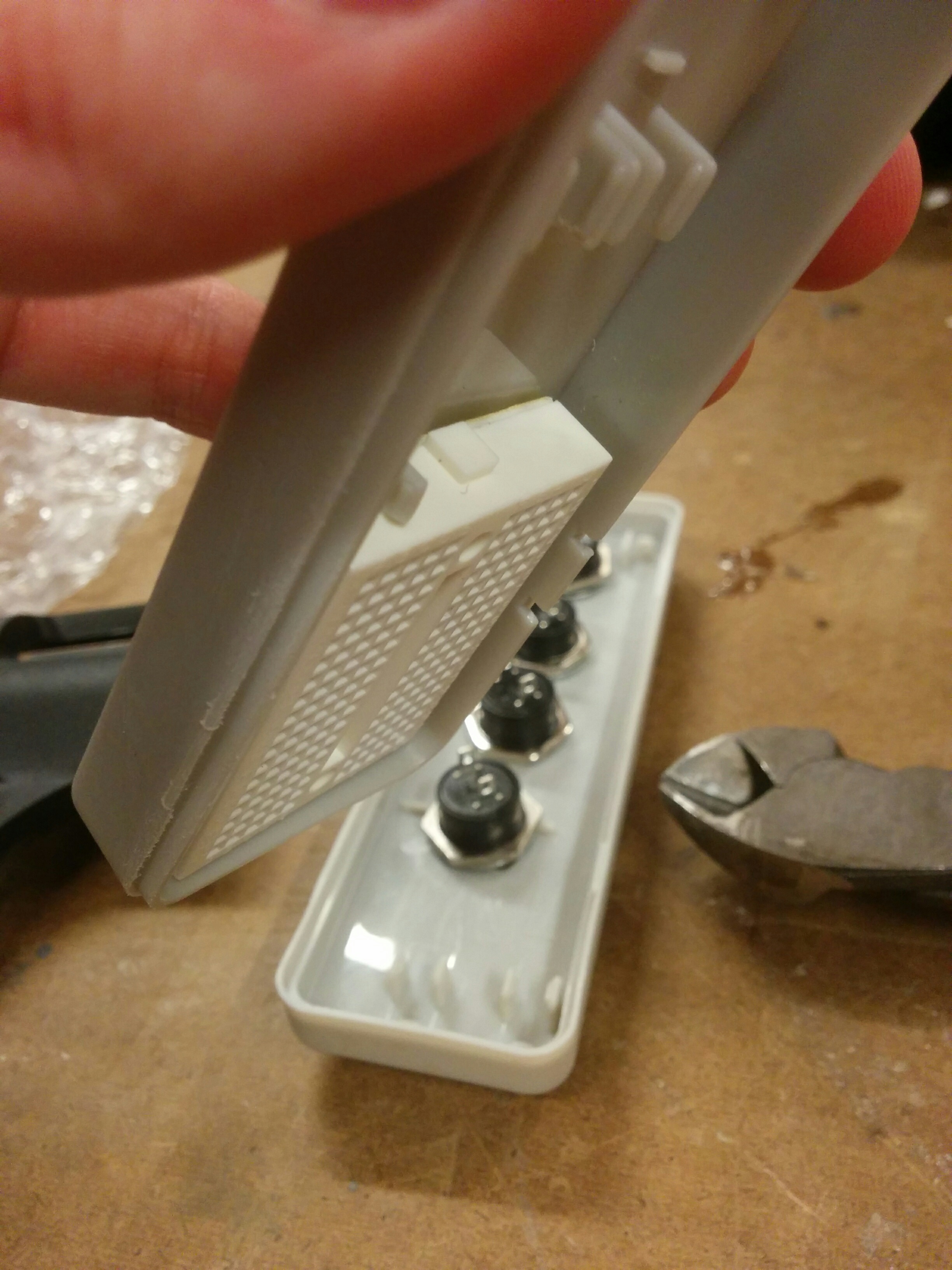
Until I put the board onto the bread board and saw I didn’t have enough clearance. The last button was getting in the way.

img_20161122_141521

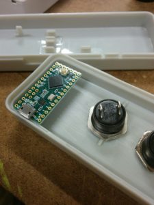
I started playing around with placing the board onto the plastic nibs that were inside of the enclosure to start.img_20161122_141808 img_20161122_142023 img_20161122_142309 img_20161122_143129img_20161122_145648 img_20161122_150719

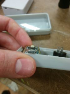
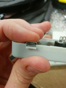
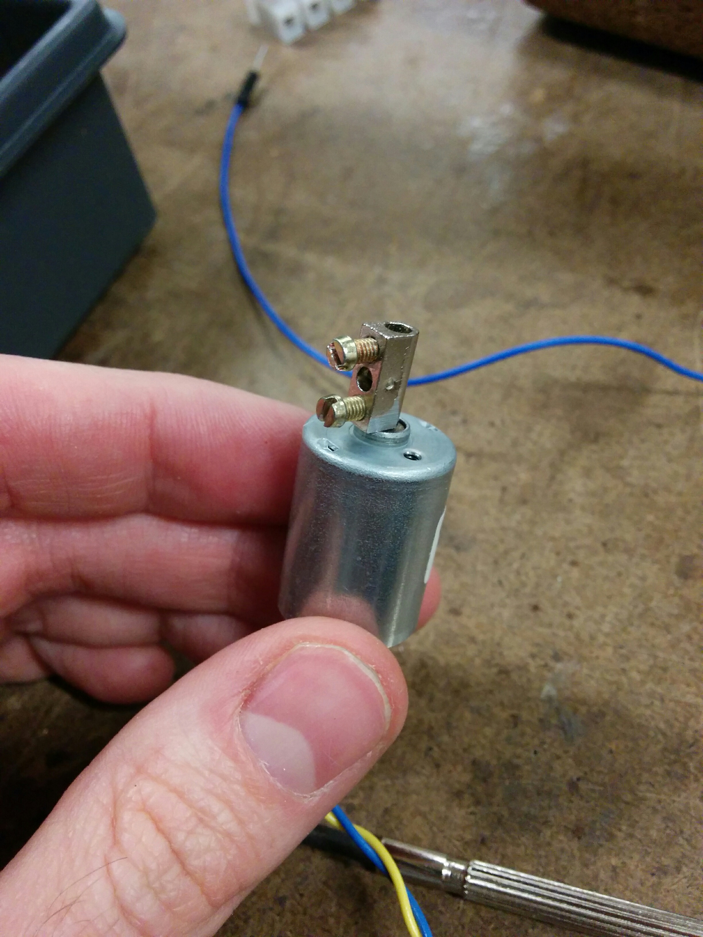
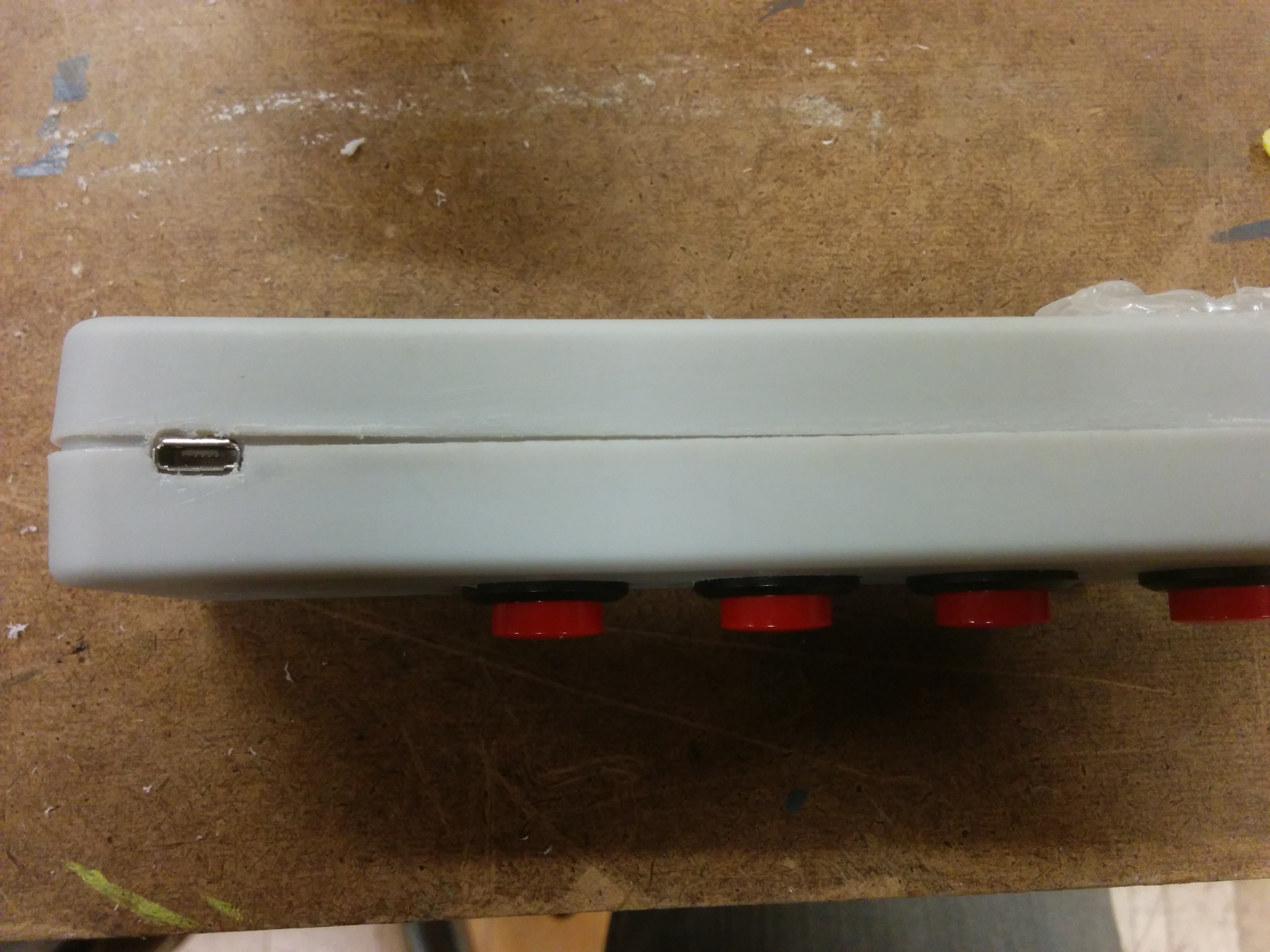
It isn’t very pretty right now, but I think for my initial functional play testing this can serve its purpose. Next step was to re-glue and attach a cable.

img_20161122_151515img_20161122_151935 img_20161122_152229 img_20161122_152236 img_20161122_152317

Once I had gone all in on my enclosure choice, it made it a little difficult to go back. But I think after this assignment I’m definitely going to re-asses my options. For my playtesting, I might wind up kind of hacking this thing apart into something resembling less of a traditional enclosure for the sake of being able to re-wire and re-position things quickly. But I certainly learned plenty about what was possible in terms of pre-made enclosures and will feel comfortable about going to the drill press to quickly produce little homes for my projects.

PComp Final: Phase 0-1

After presenting my initial concept to the class, my next step was to create a playtesting prototype. I felt fairly confident that I knew what it would feel like in my hand, but it really did help to have something in my hand. This was made from prototype plastic. After warming it up, I flattened it out like a pancake. Then I wrapped a microphone in saran wrap, then wrapped the prototype plastic around the microphone. I put it into the freezer to harden, and then used a dremel to generally trim the shape. Once satisfactory, I warmed up the piece again, just soft enough to be able to push some push buttons securely into it’s surface.

I used this as a conversation piece when conducting user interviews. I went to the Tisch performing studies floor to talk to different artists about the possibilities of using this device, and what features they might want or wish for it. While there were some wonderfully exploratory and experimental ideas, there were also some practical features that were desired for experimental performances. One artist brought up the issues of timing, synchronization, and the need for discrete control and messaging systems in regards to controlling a performance seamlessly. There was a visit to the Music Tech program where I talked some researchers who gave me some input but also some history and terminology around somewhat similar approaches. I also went to the Steinhardt, and talked with faculty in the Vocal Performance program. We had great conversations about vocal science and pedagogy. However, I learned that the Vocal Performance process eschews microphones almost entirely! This is why you do user interviews.

Then in class we did some play testing. I was very curious as to how people would naturally grip the prototype without any prompting. This was very useful to me to think about input placement and functionality. I could go on and on about this, but I think I will leave the elaboration for a different post. For now, let’s look at the grips:

img_20161109_130940 img_20161109_131610 img_20161109_131611 img_20161109_131616 img_20161109_132056 img_20161109_132922 img_20161109_132927

It was interesting not just to hear what people thought would work well, but to simply see how they held and interacted with the prototype without prompting. This was a great help in planning out button sizing and placement.

I had come to a crossroads, however. Seeing people interact with the piece further re-iterated that I should further focus on an activity and a user. I am confident that I will continue to work on this in the future, so I’m not too worried about making a “wrong” choice. With that in mind, it made sense to stick with my first instinct; a device specifically for musical interaction.

With that in mind, here is my first system diagram:

pcomp_final_sys-diagram

Technical diagram:

img_20161113_213828


And bill of materials:

bom_0-1


I’m going to be using a Teensy LC for it’s size, cost, and ready to rock MIDI implementation (that I’ve used before on the Teensy ++). For now, I am going to try to work some kind of enclosure of bent acrylic, but I am expecting to play around with a few different enclosure types before fully settling.

My parts are ordered and I will be doing some acrylic tests (and consulting) over the following week.