I’m moving along with my Physical Computation final, trying to stay on track while still taking things step by step. Benedetta keeps reminding us to start with the basics to make sure everything works before getting started with something larger. Maybe it is because I’m also doing Intro to Fabrication, but I keep thinking about end stage type decisions. It is good to reorient myself and start at the beginning.
My Teensy LC came! And it is very… teensy. Also, it came without headers and I wasn’t sure which ones to get. Benedetta suggested the combination male and female ones, but we didn’t see any specific header pairings for the Teensy on the Adafruit site. I wound up getting the Arduino ones, and then also a set of male headers as well. And I’m glad I did:
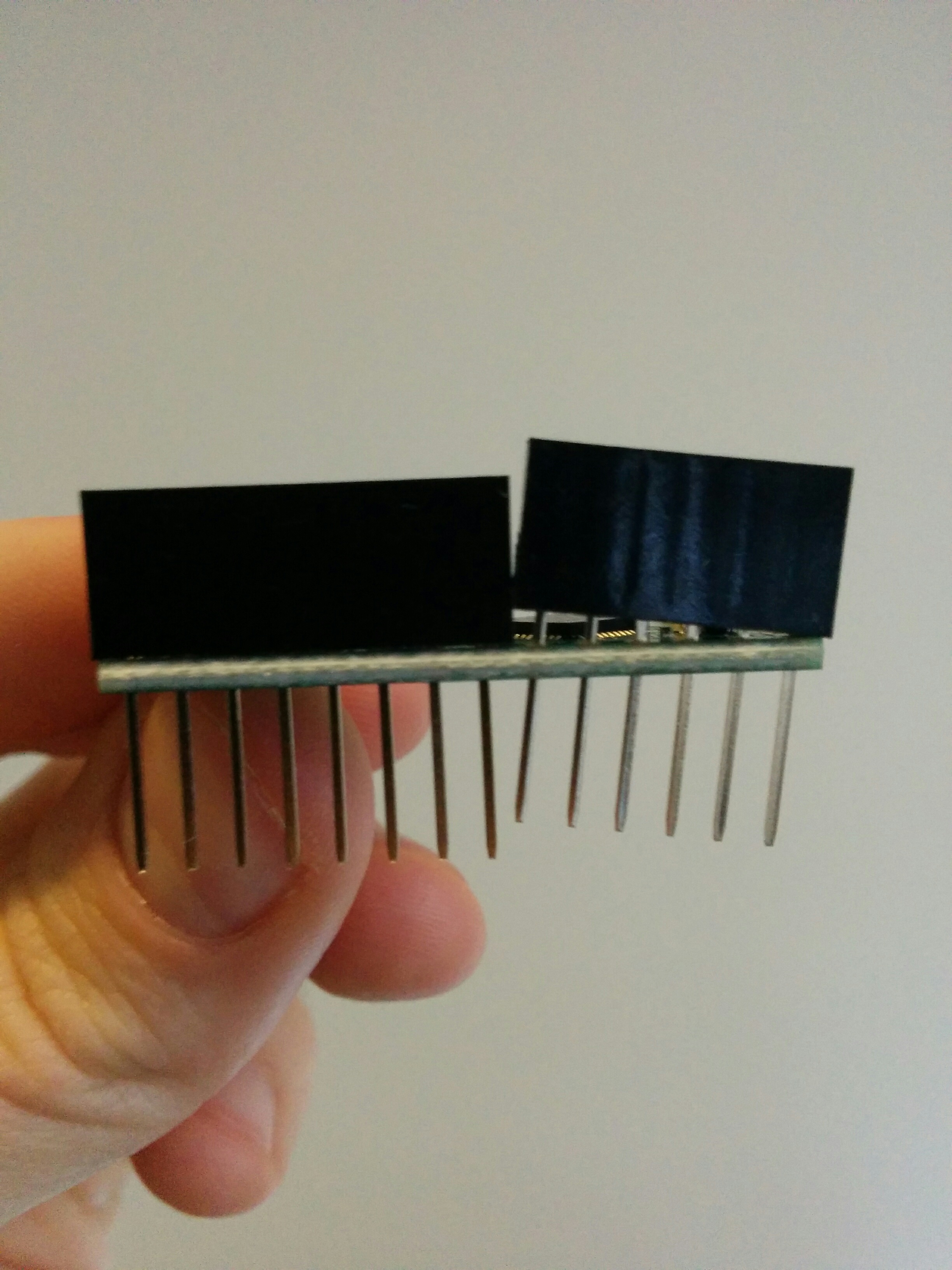
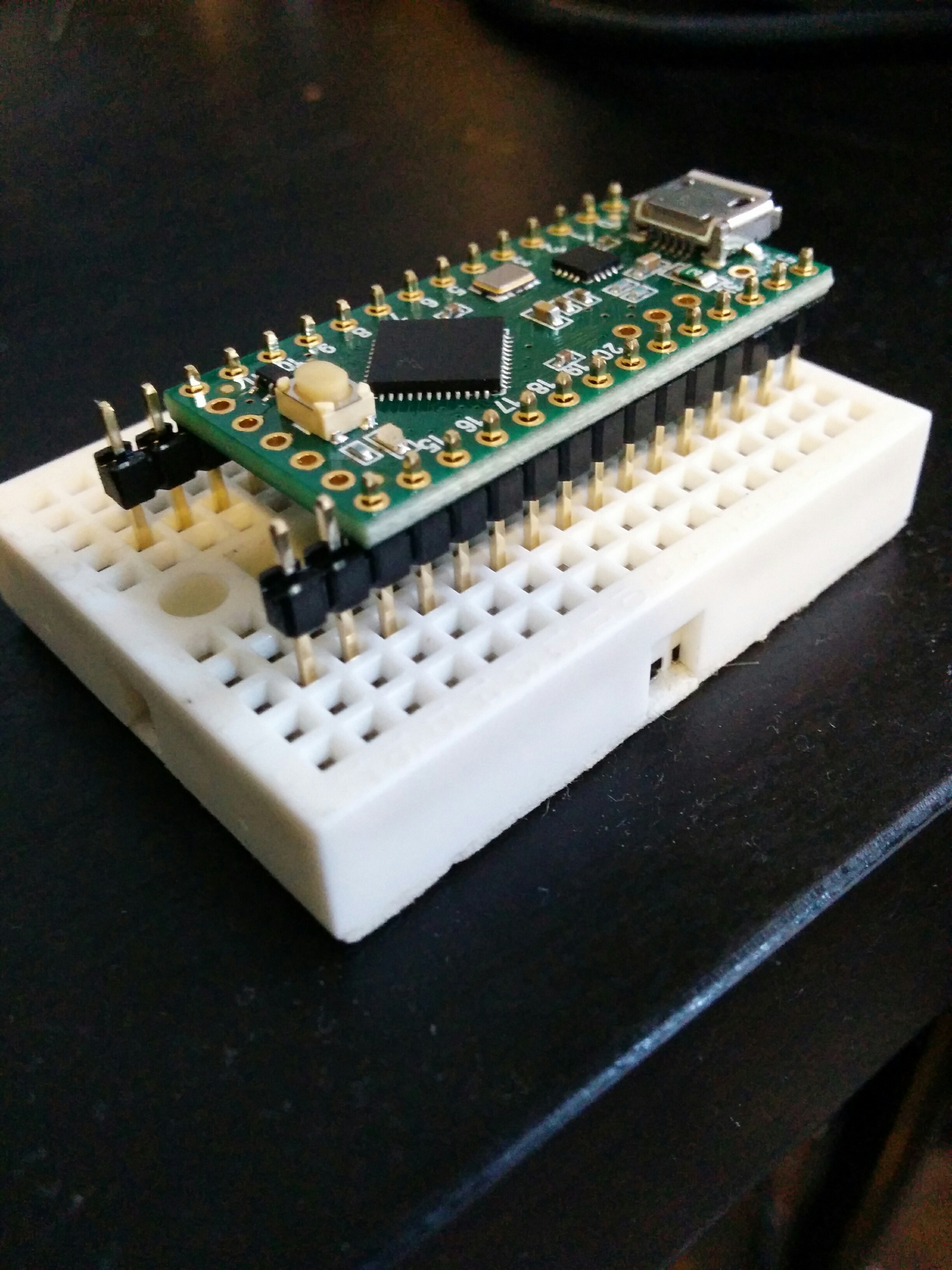
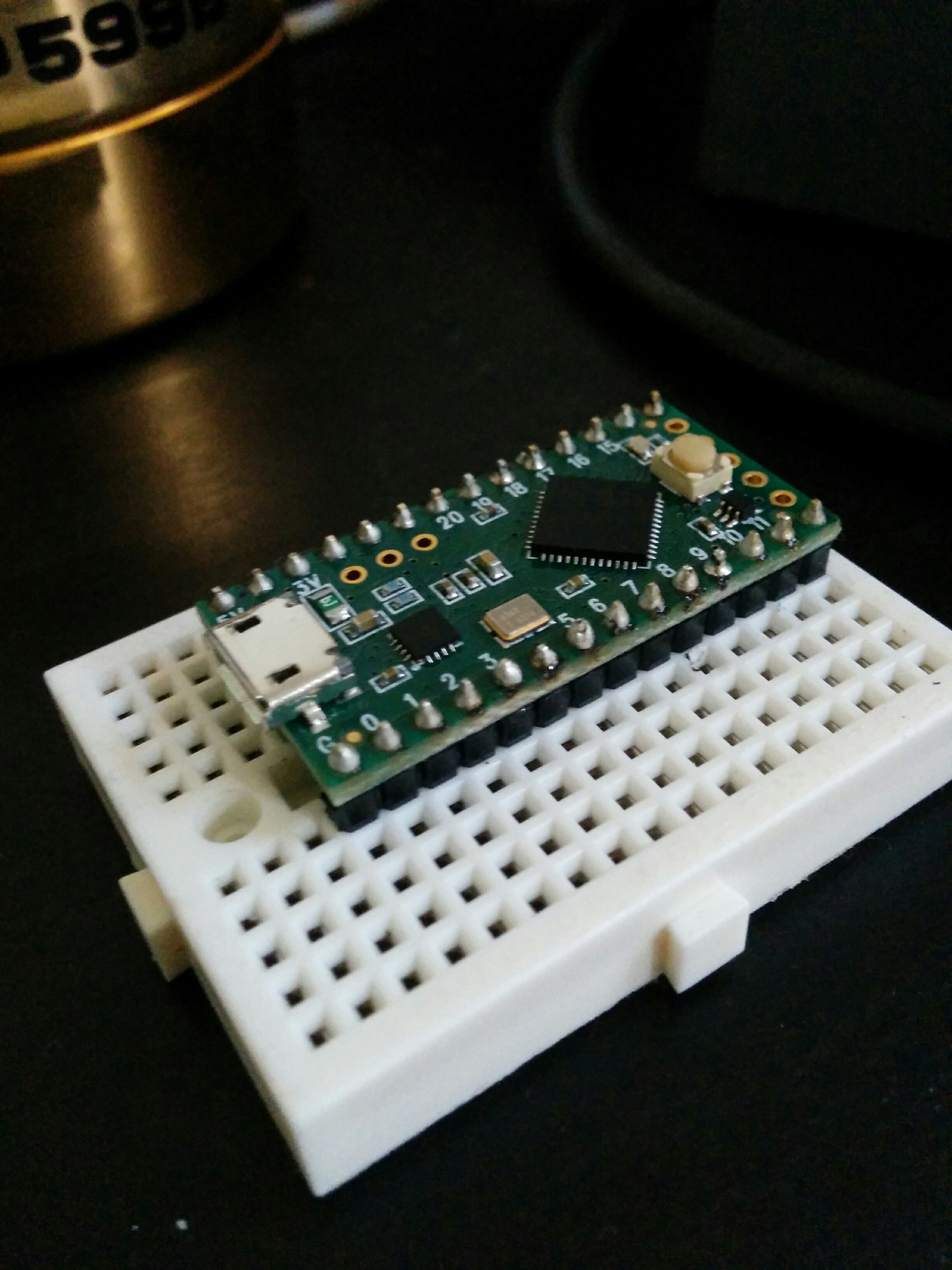
There weren’t male and female headers that spanned the entirety of the Teensy’s pins. I saw that the two separate pieces would add up to what I needed, but I didn’t expect them to not be able to sit side by side. After this, and looking at many, many Teensy how-tos and tutorials, I noticed that everyone seems to use it with a breadboard and male headers. I wound up using the strips of male headers instead (glad I ordered more than I needed!).
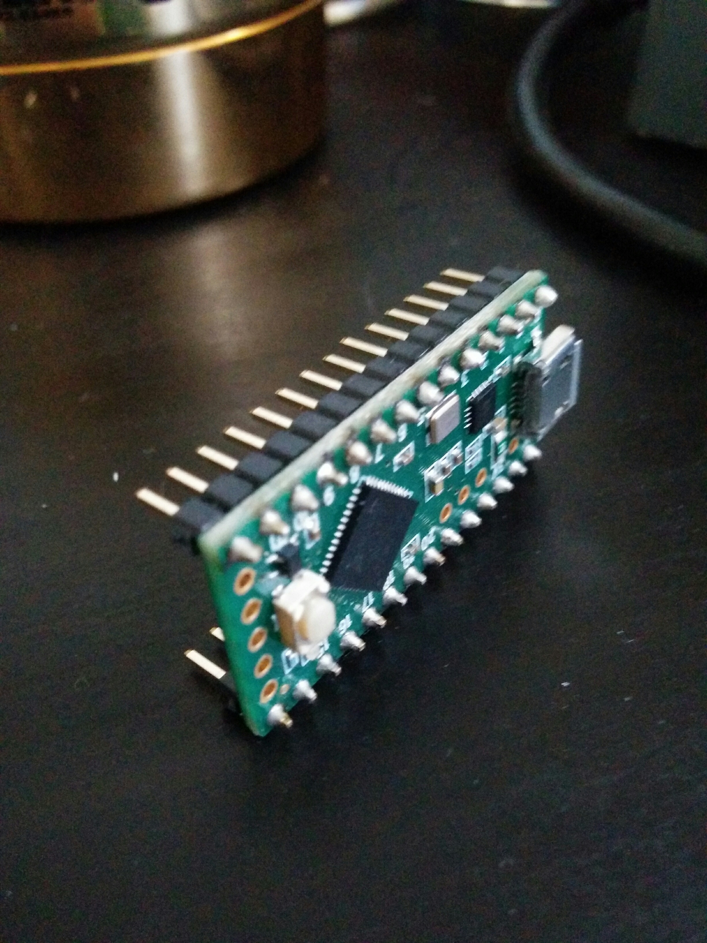
I snapped off the last two pins on each row and soldered everything together.
You’ll notice that there are pins on the end that don’t have headers in them. This was also done by example, seeing what other people were doing online with posted tutorials. I had access to the ground, source, and pins that I wanted, so I figured I would let it go for now. Plus, it lets me straddle the middle of the board.
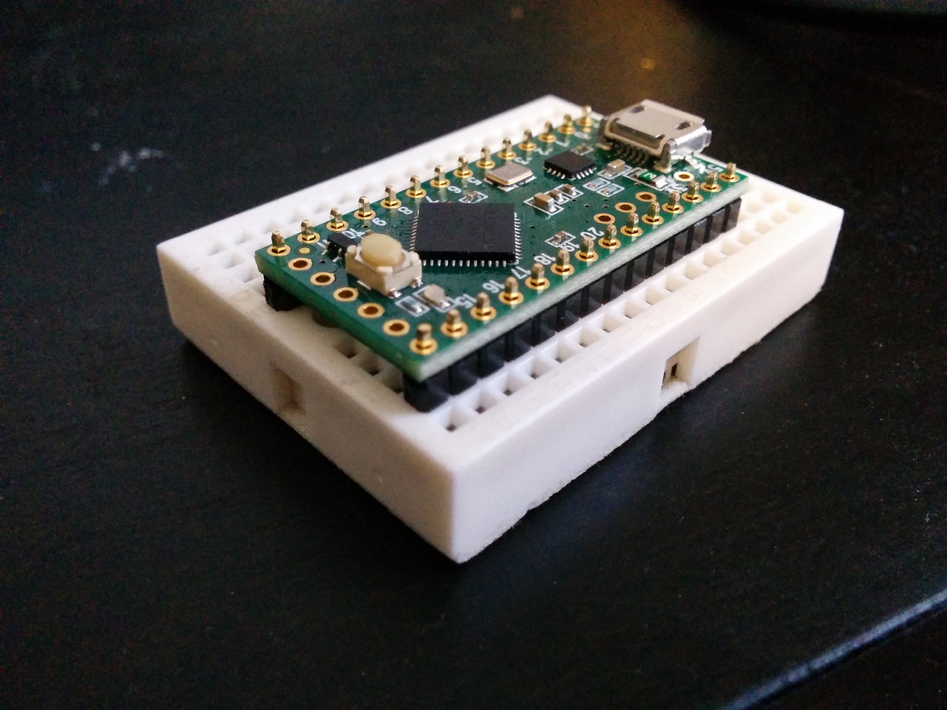
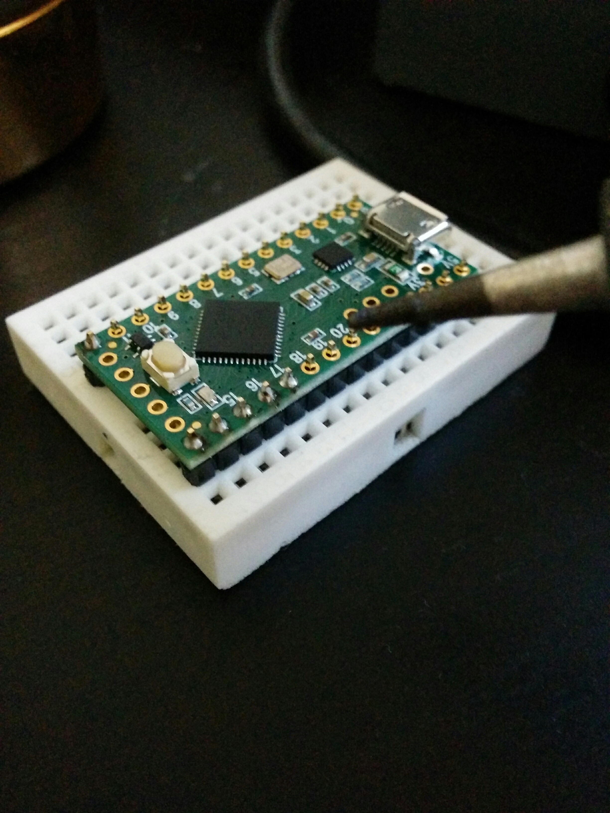
Took me a bit to get into the groove, but I got everything together. Perhaps not the prettiest… there are some burn marks here and there. But it works! Here is the blink example from the teensy library (slow blinks normal, fast blinks when pressed).
I spent a fair bit of time getting all of the Teensy software on my computer and working correctly. Wouldn’t say it is hard, but perhaps a little “fussy” depending on your luck. The most recent Arduino IDE isn’t compatible with the Teensy libraries yet, so I had to roll back my Arduino IDE version. Once I figured out that, there were some issues with loading programs onto the board. The error messages are different with the Teensy, and there can be extra steps when programming it. It was giving me problems. Going step by step, piece by piece, I figured it out. I had used a micro USB cable I had lying around… and it seems that it only transmits power. NO DATA.
Once I swapped it for a functional one, I was able to upload to the board and got that blink sketch going. You’ll note that I’m not using any resistors on my breadboard. The Teensy button examples state that every digital i/o has a pullup resistor and that you can use an active low i/o implementation with the board. Feeling good about that, I continued with further experimentation and got the Teensy to output MIDI and send it to a testing Max MSP patch that I setup. I used an existing MIDI controller I had to make sure things were working, and then threw the Teensy into the mix:
After my headaches with data-less USB (and I mean…really? Just… why??), I received an all new appreciation for functioning hardware. There is a little fussiness with detecting the MIDI events in the software, but I’m confident that I can optimize that just fine when the time comes.
Next I will be getting more buttons going, streamline the wiring and working on a decent temporary mounting solution so I can get some initial functional playtesting going. I’ll be updating next with a more detailed timeline for the next couple weeks.
This week we were tasked with making enclosures. Since we’ve also been ramping up towards the end of Intro to Physical Computing, this assignment coincided with making some next-step proof of concept builds for my final project in that class.
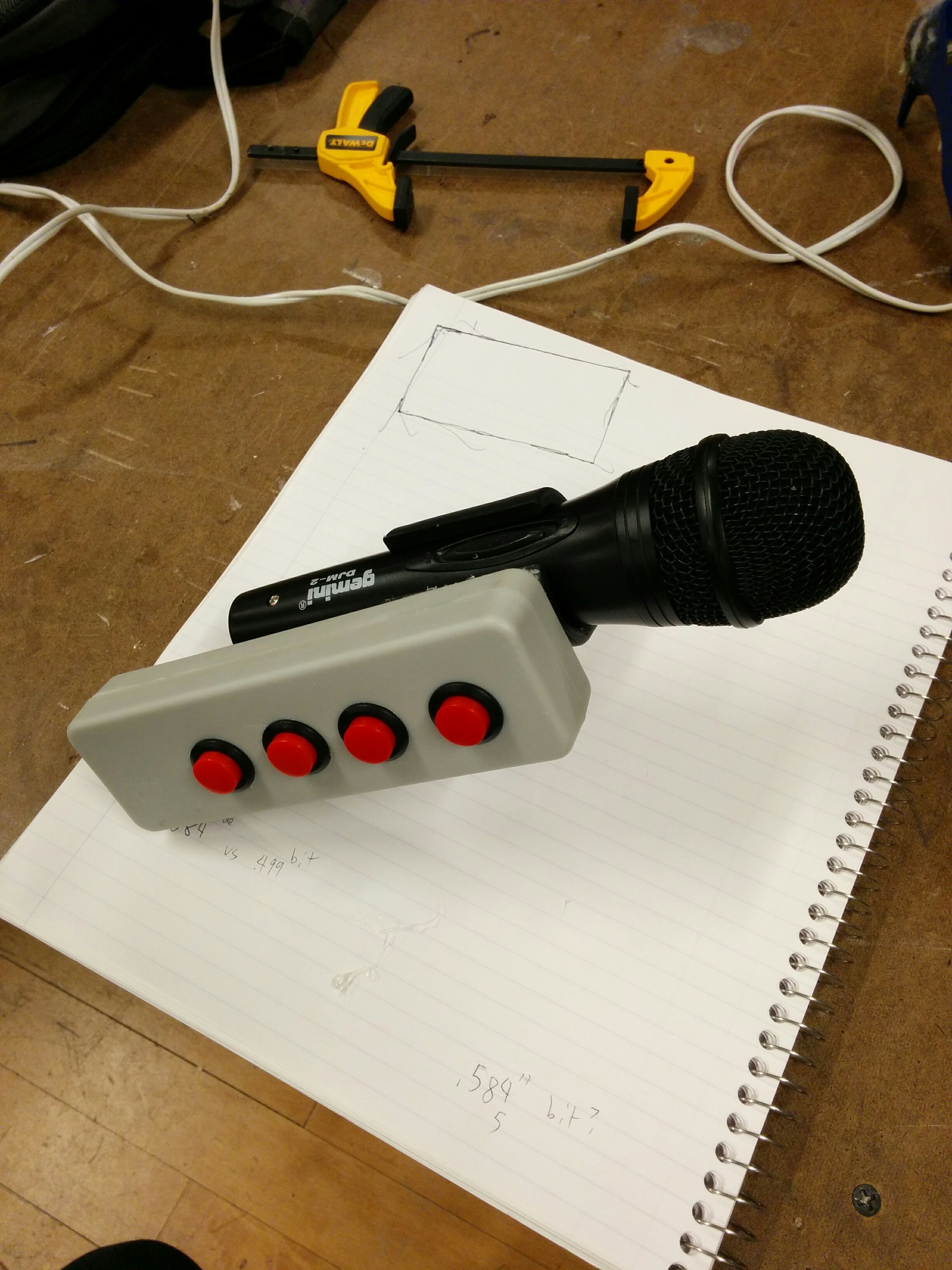
I asked Ben for some advice, and was convinced to start out more basic. My initial instinct was to try and create a curved shaped enclosure right off the bat, but it makes more sense to start simple. Using a normal pre-made enclosure and then attaching it to a microphone clip seemed to be a good first step.
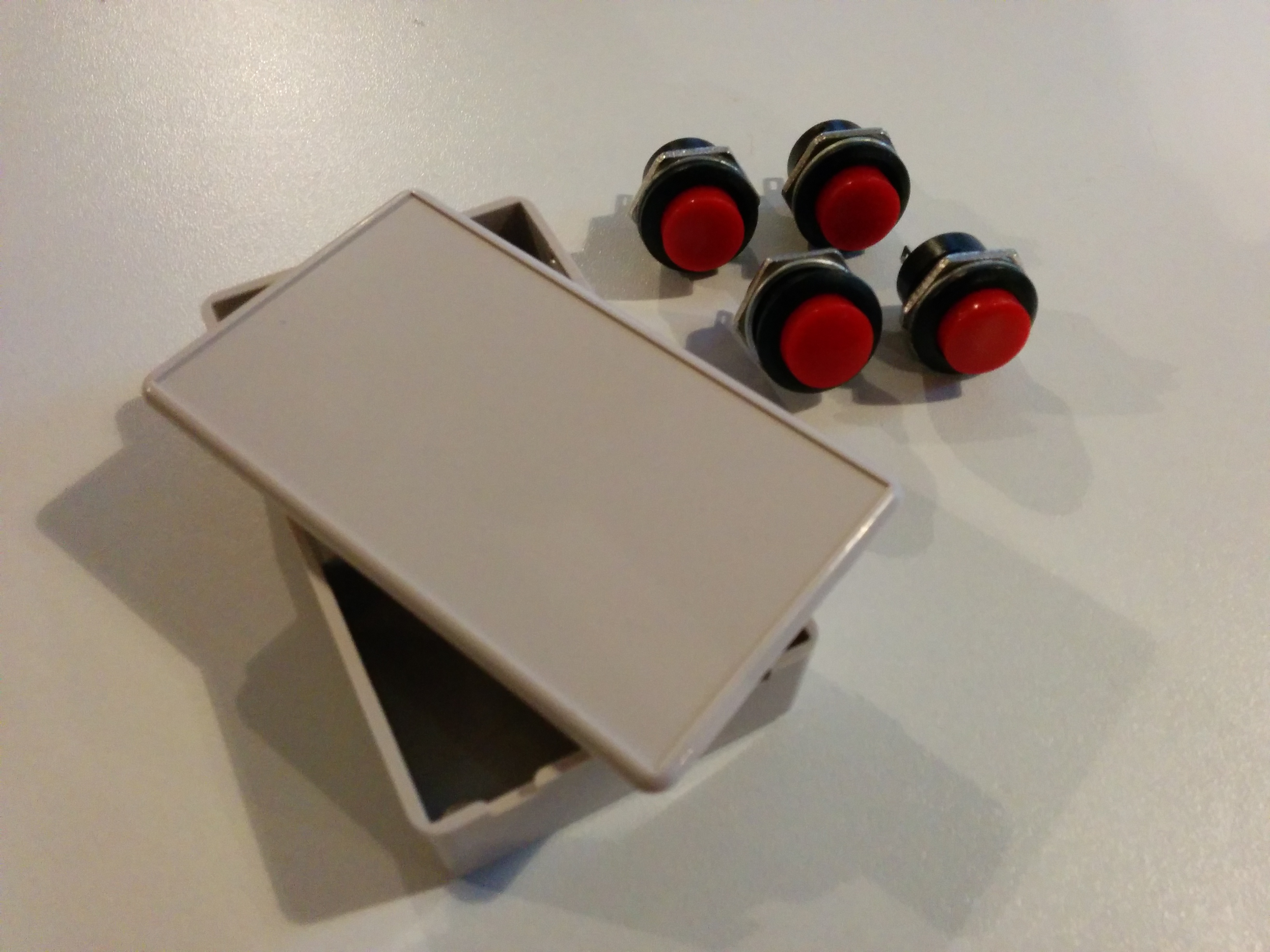
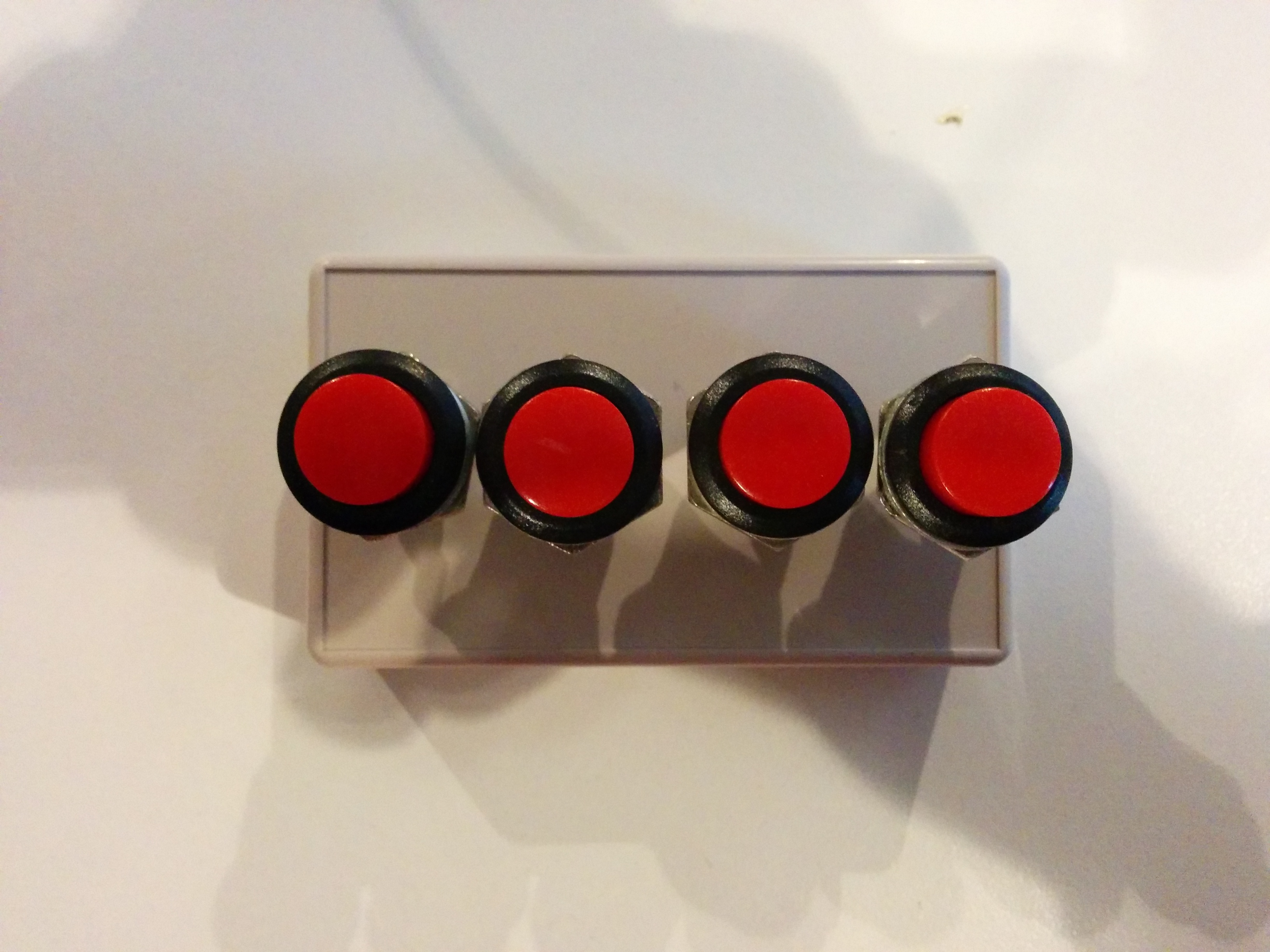
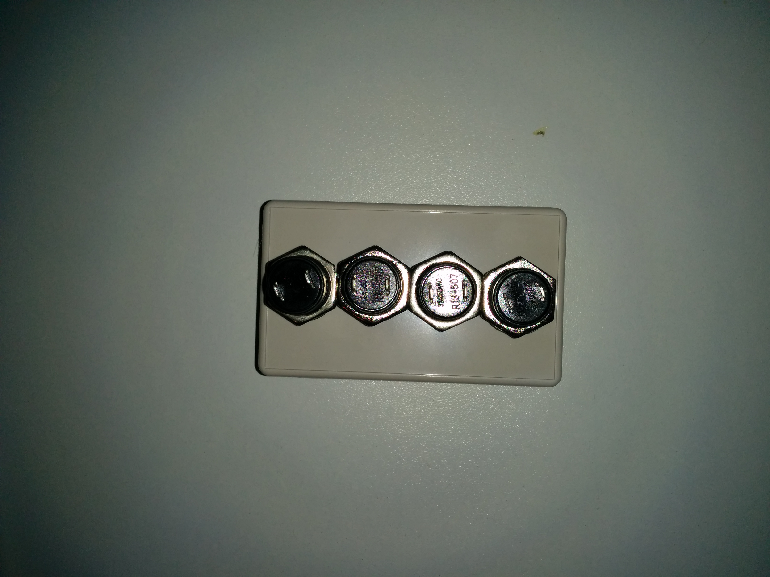
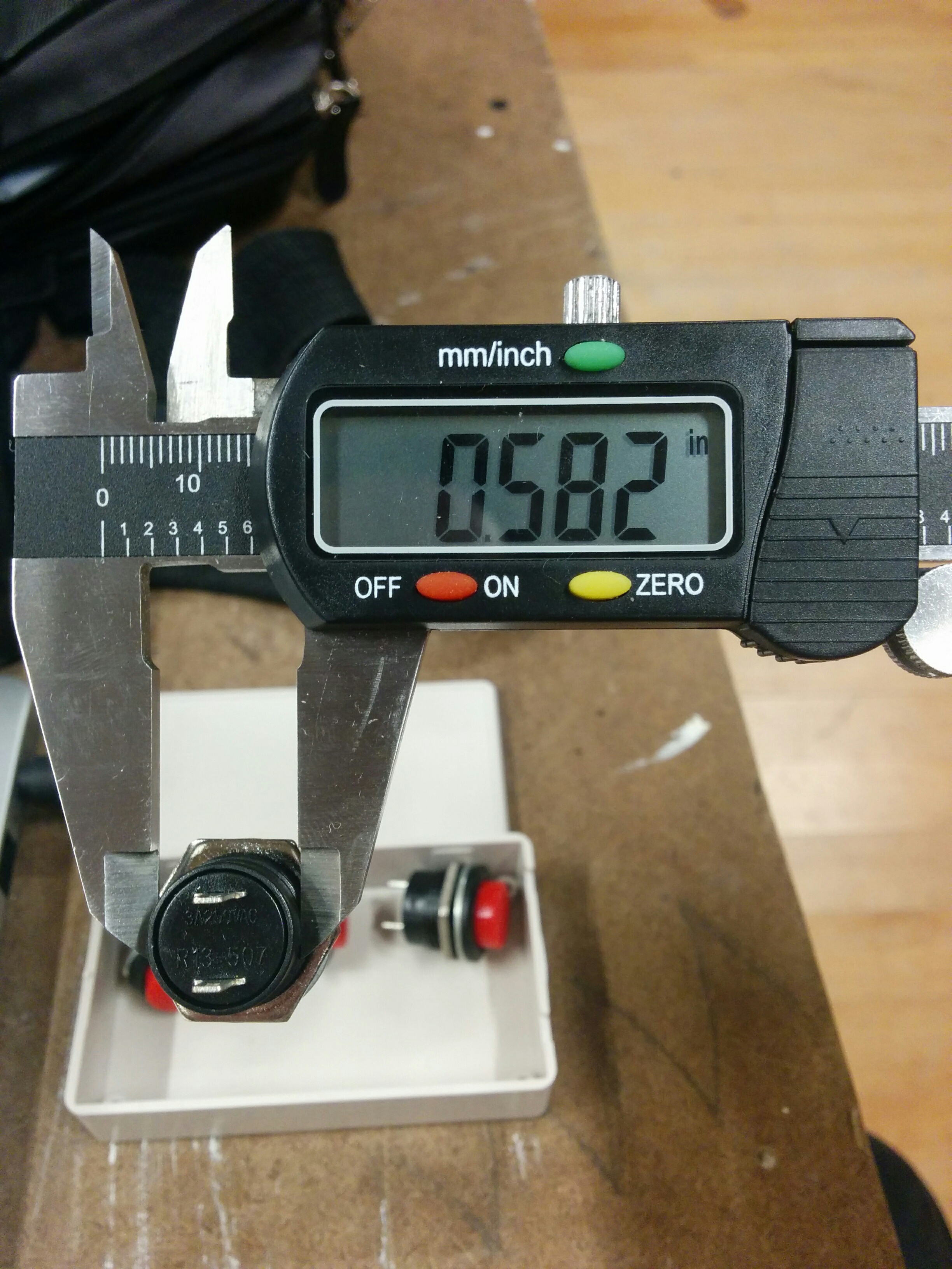
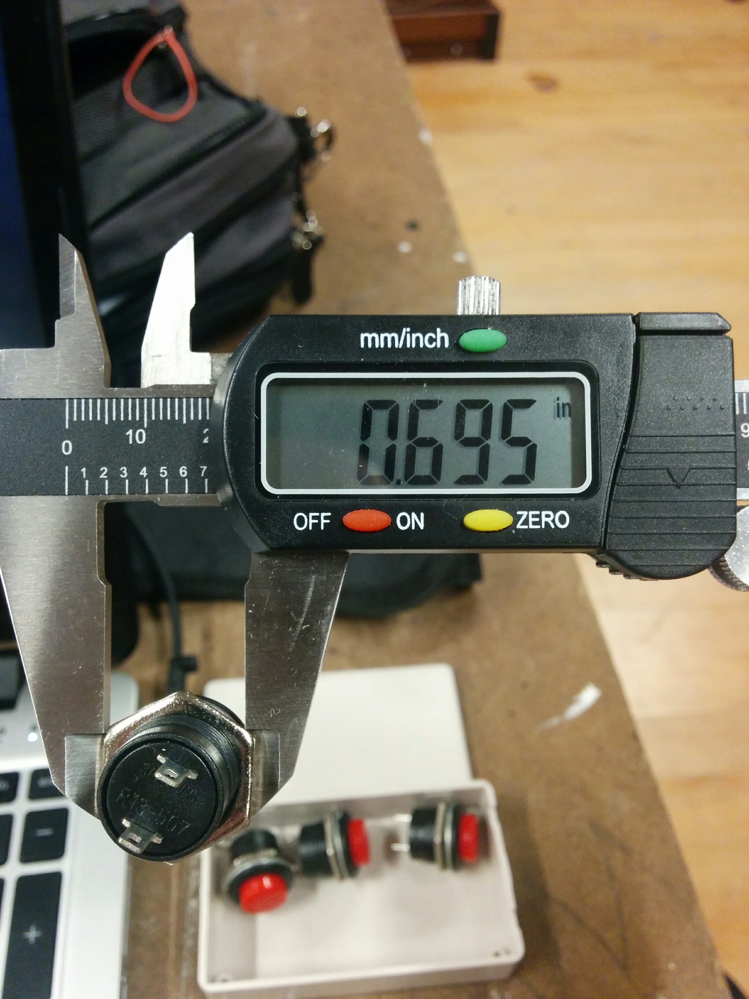
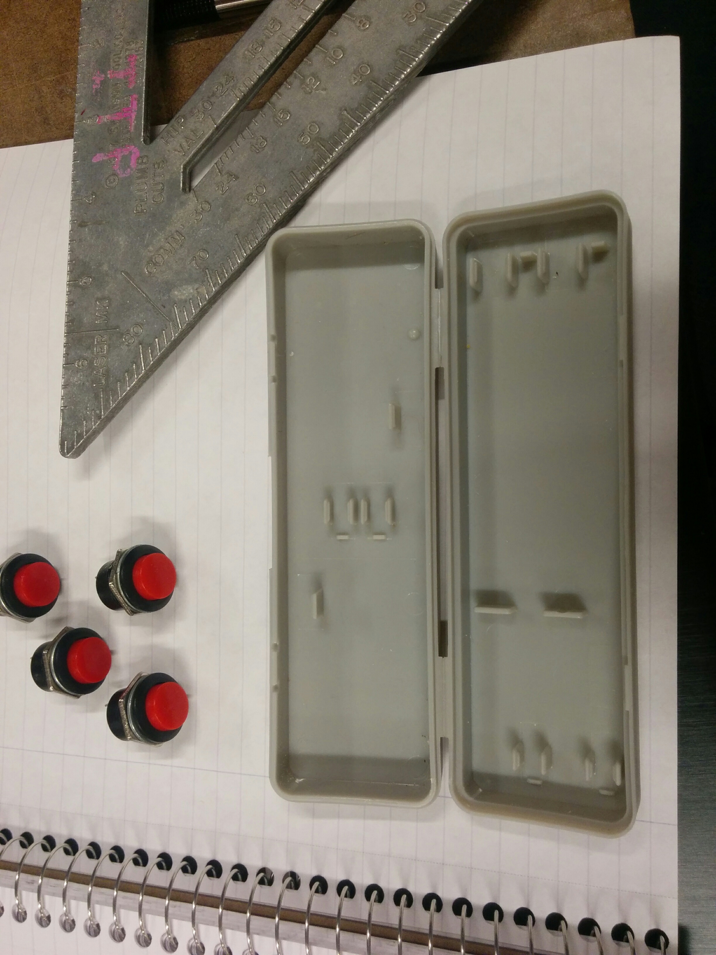
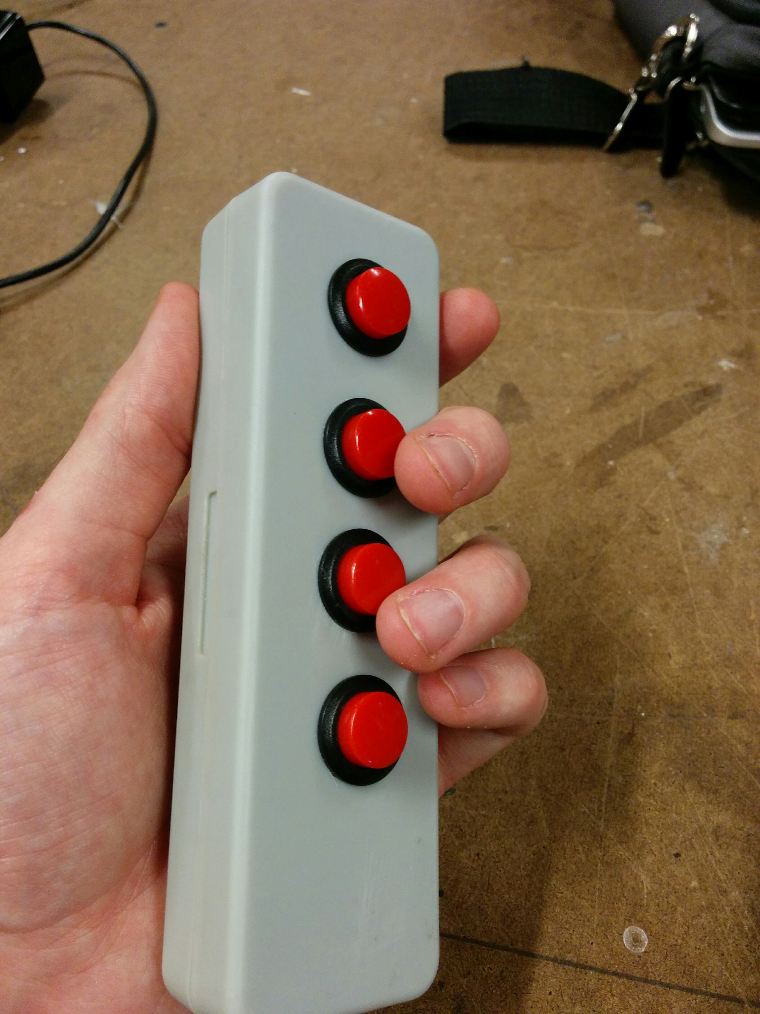
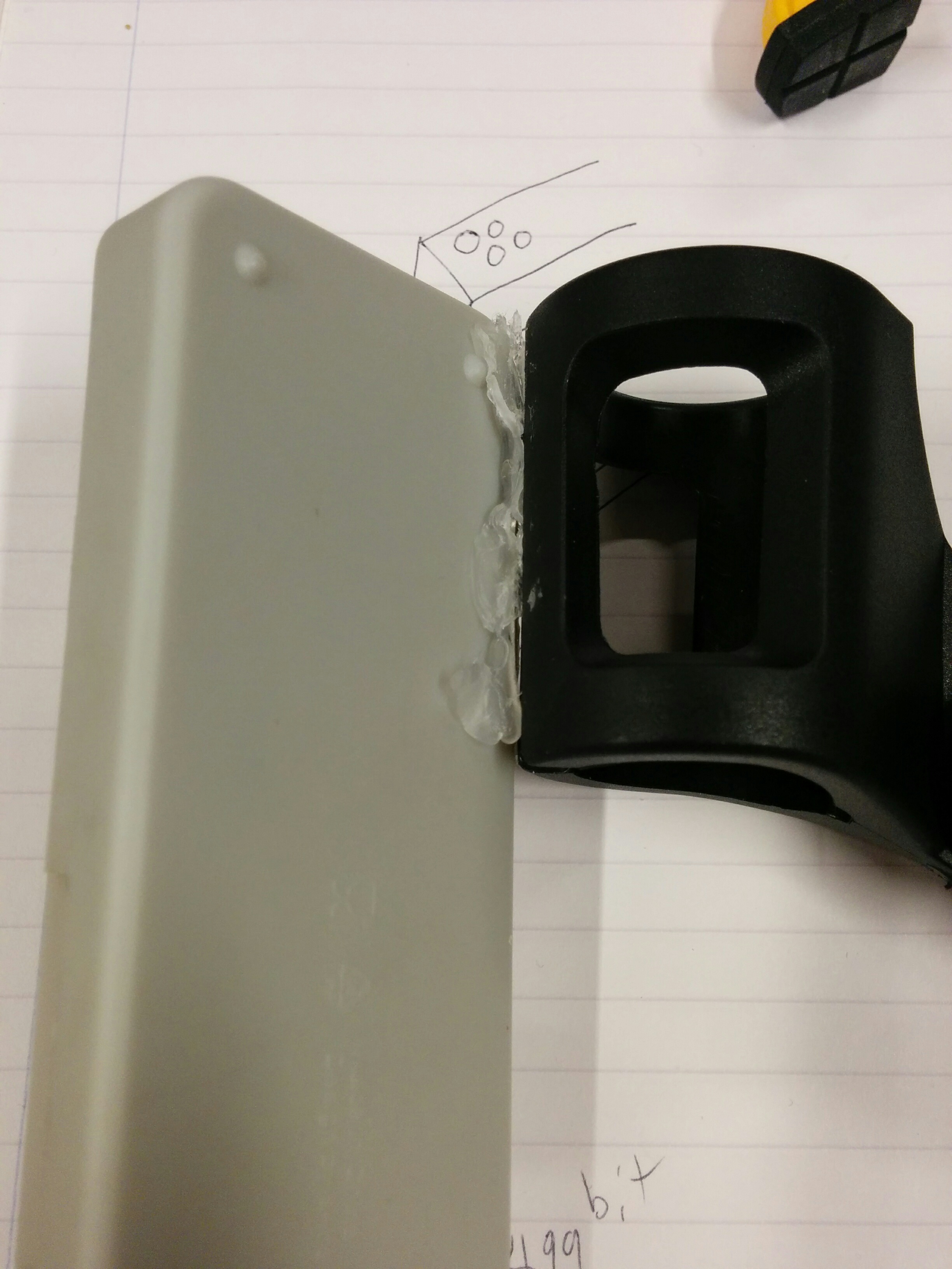
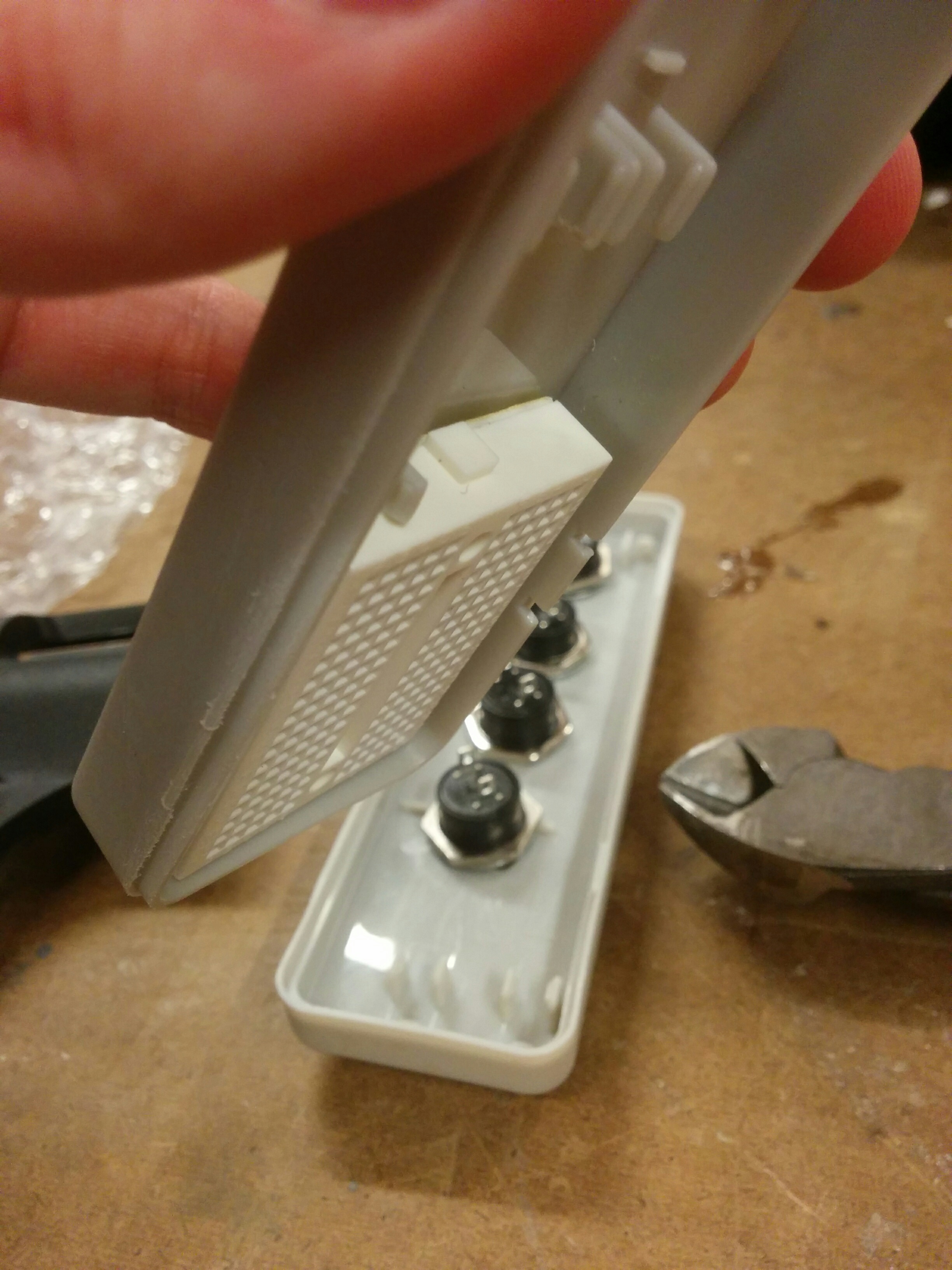
I went to Tinkersphere and bought a project enclosure that complimented the size of my microphone clip, and then bought surface mount buttons for it. They were the rare kind that make no noise when you press them (if I am using this with a microphone, it is best to avoid clicky noises). With these two constraints, my choices were made fairly quickly for me. However, I wasn’t so sure about the spacing:
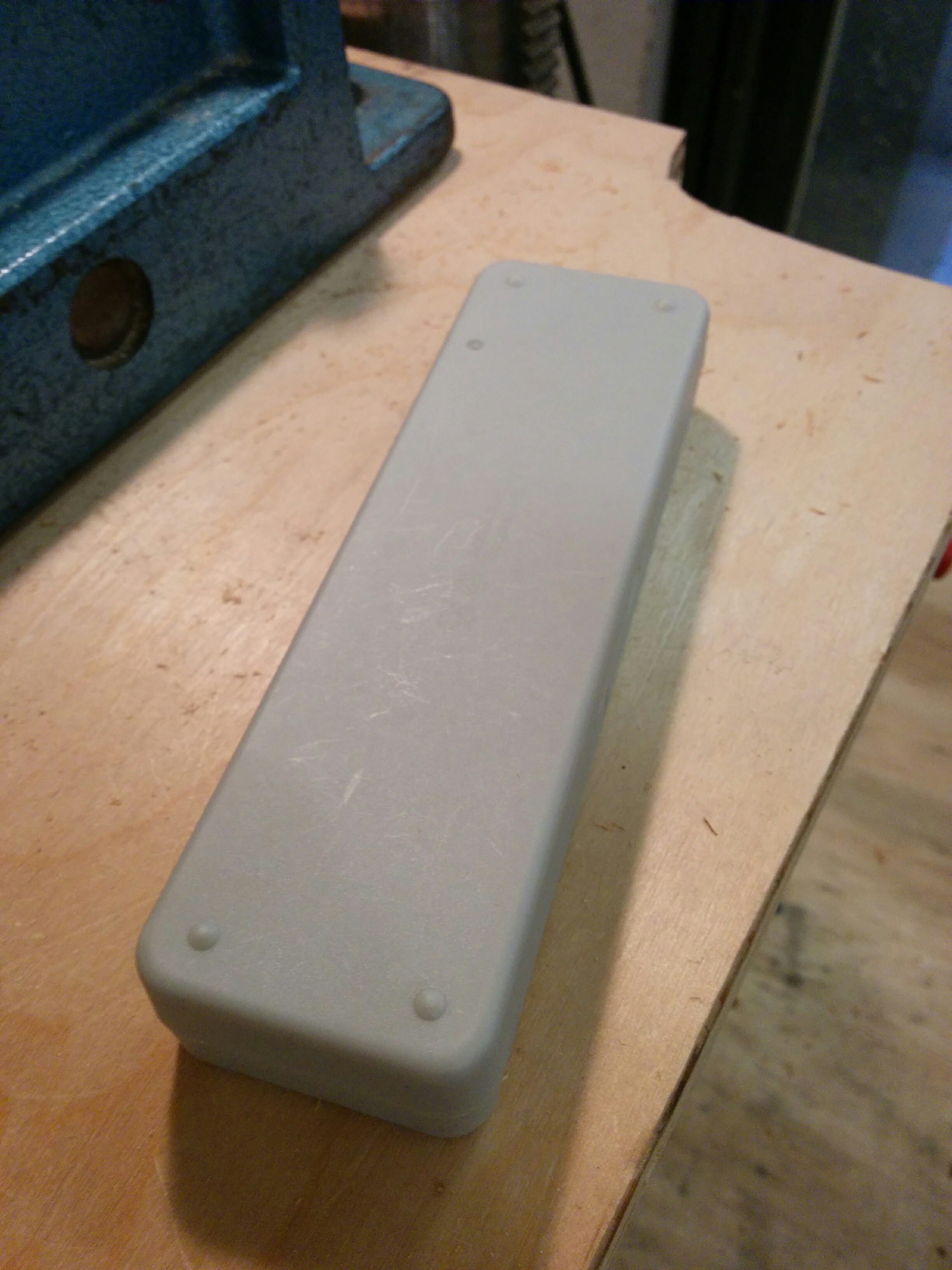
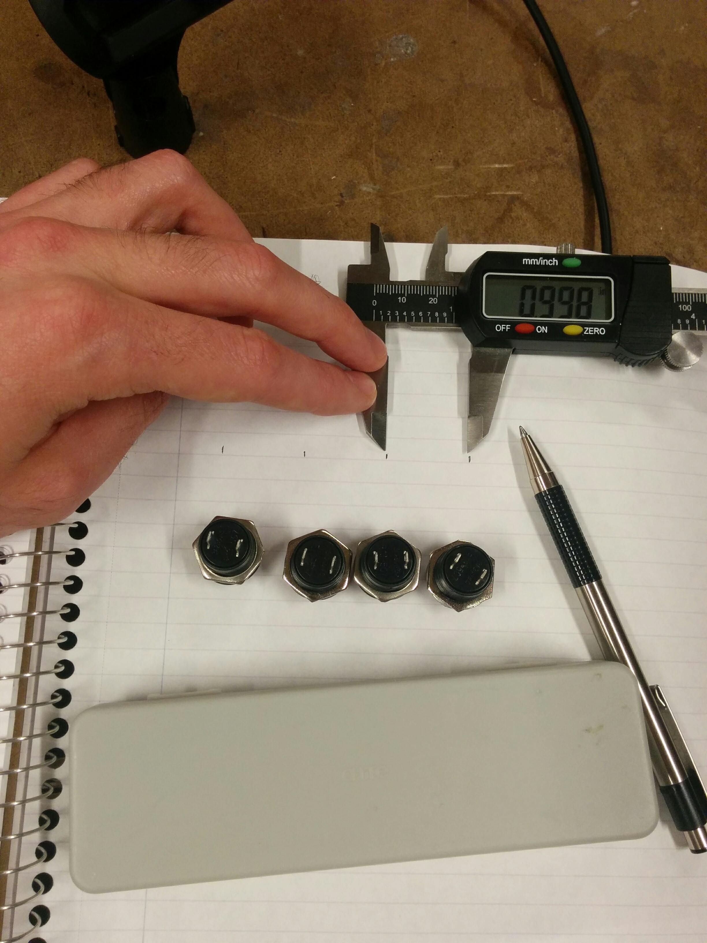
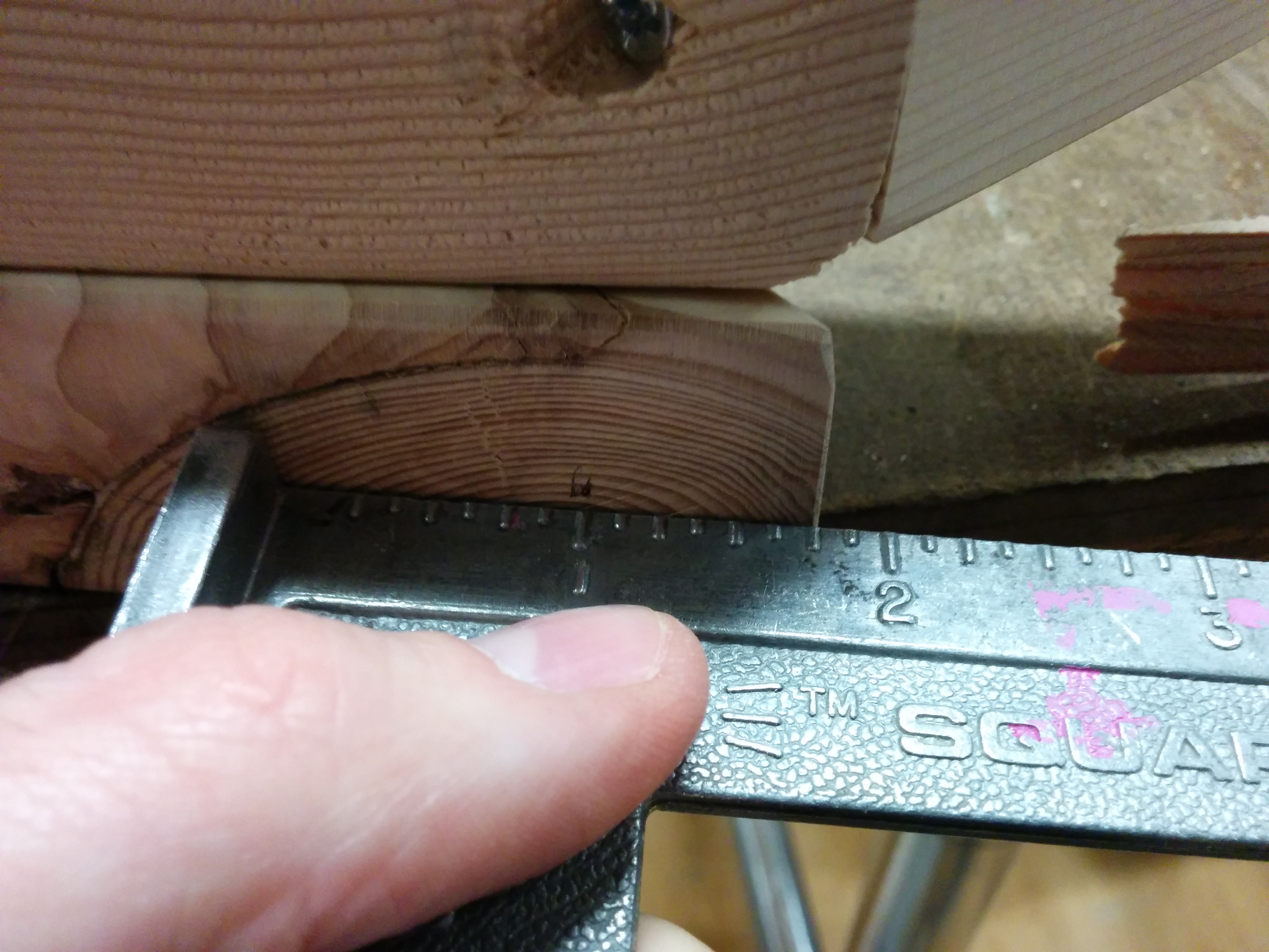
While perhaps technically possible to fit all the buttons onto the surface, I started having second thoughts when I brought everything back to the shop and was able to measure. Luckily, Ben had given me a different enclosure to try out. The more I looked at it the more it made sense:
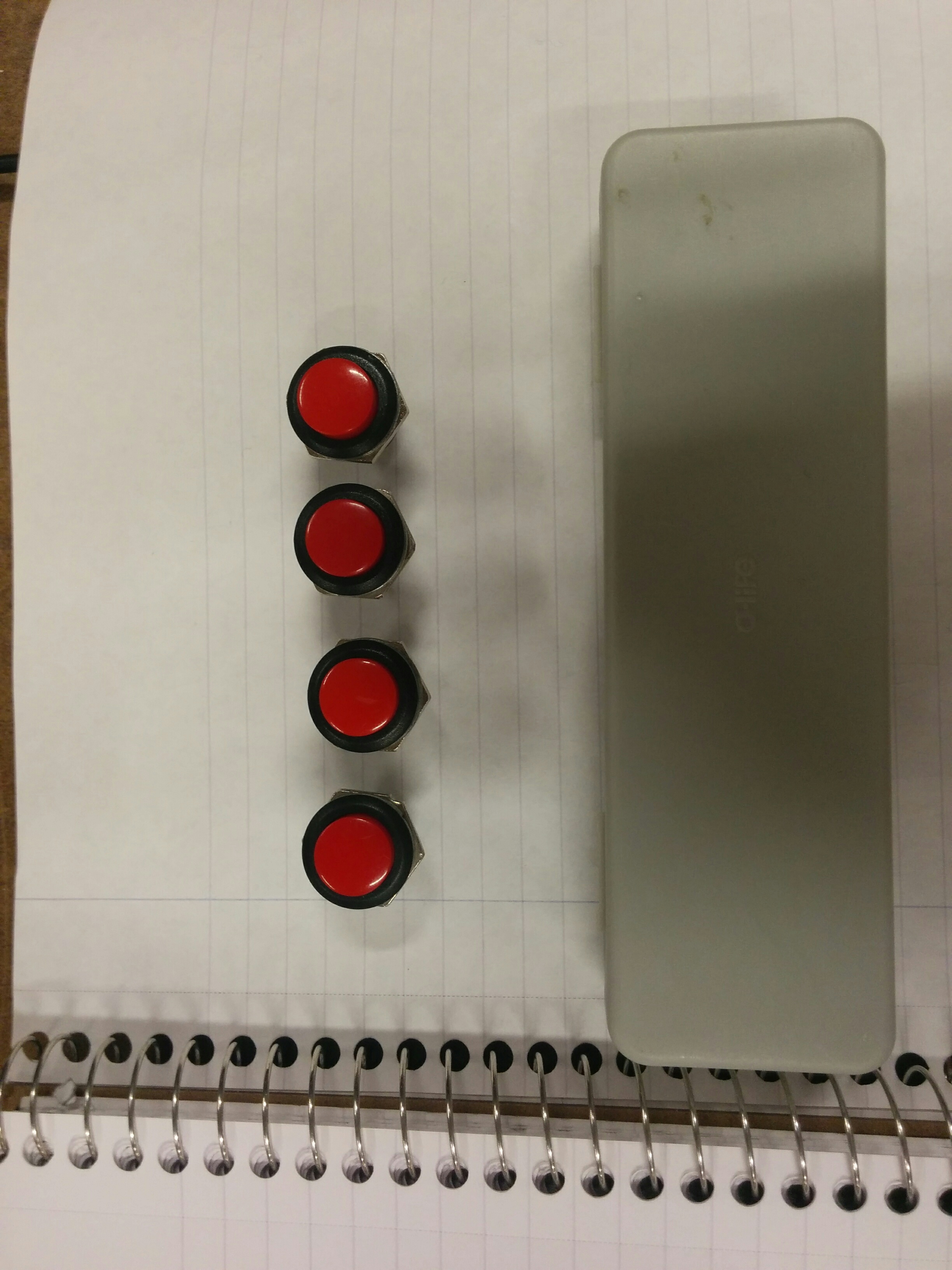
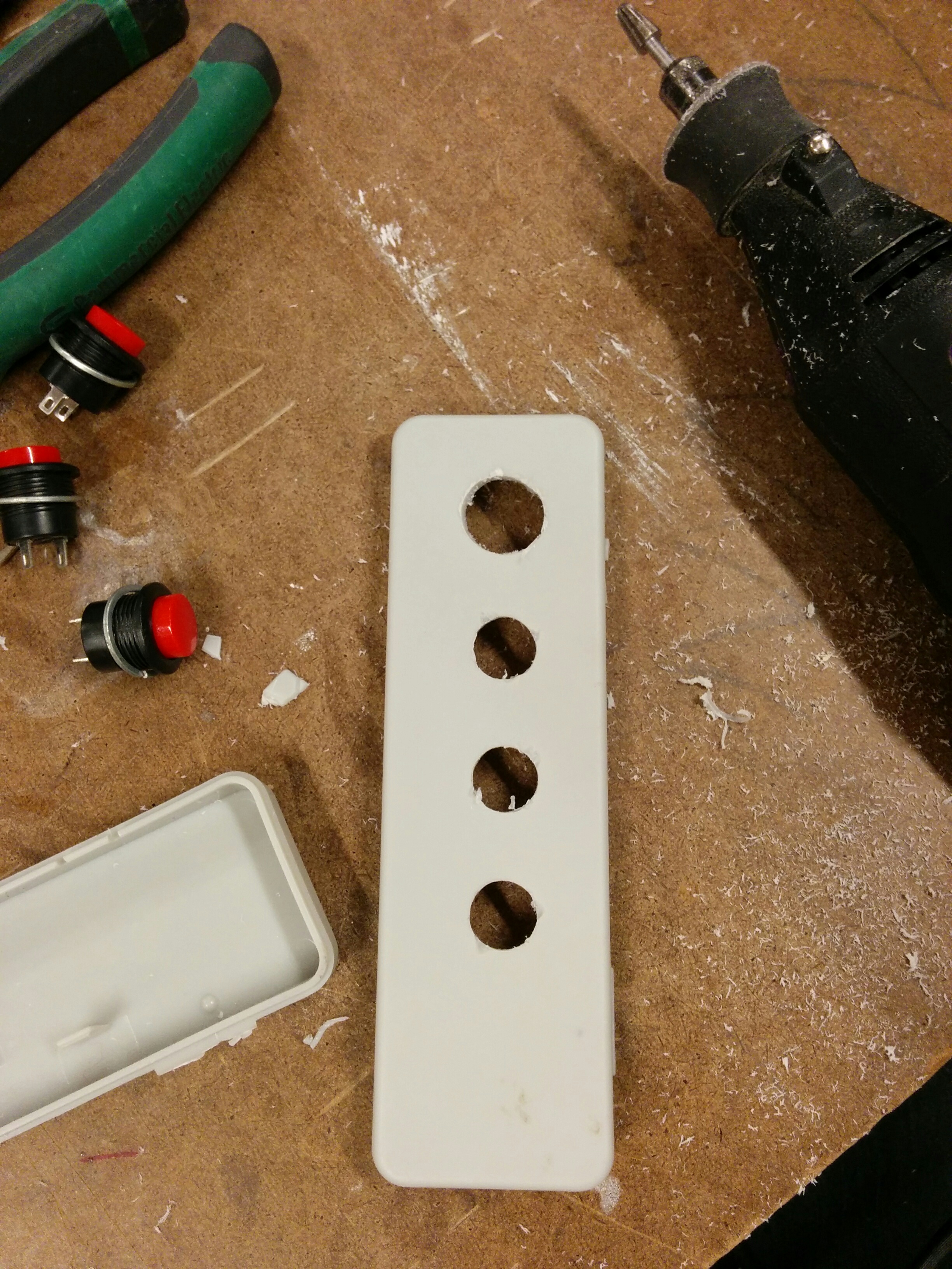
“Small is hard” kept echoing in my head, and even though larger I felt like this could work decently for my play testing. I went to measure out the distance between buttons and started making some holes on the drill press.
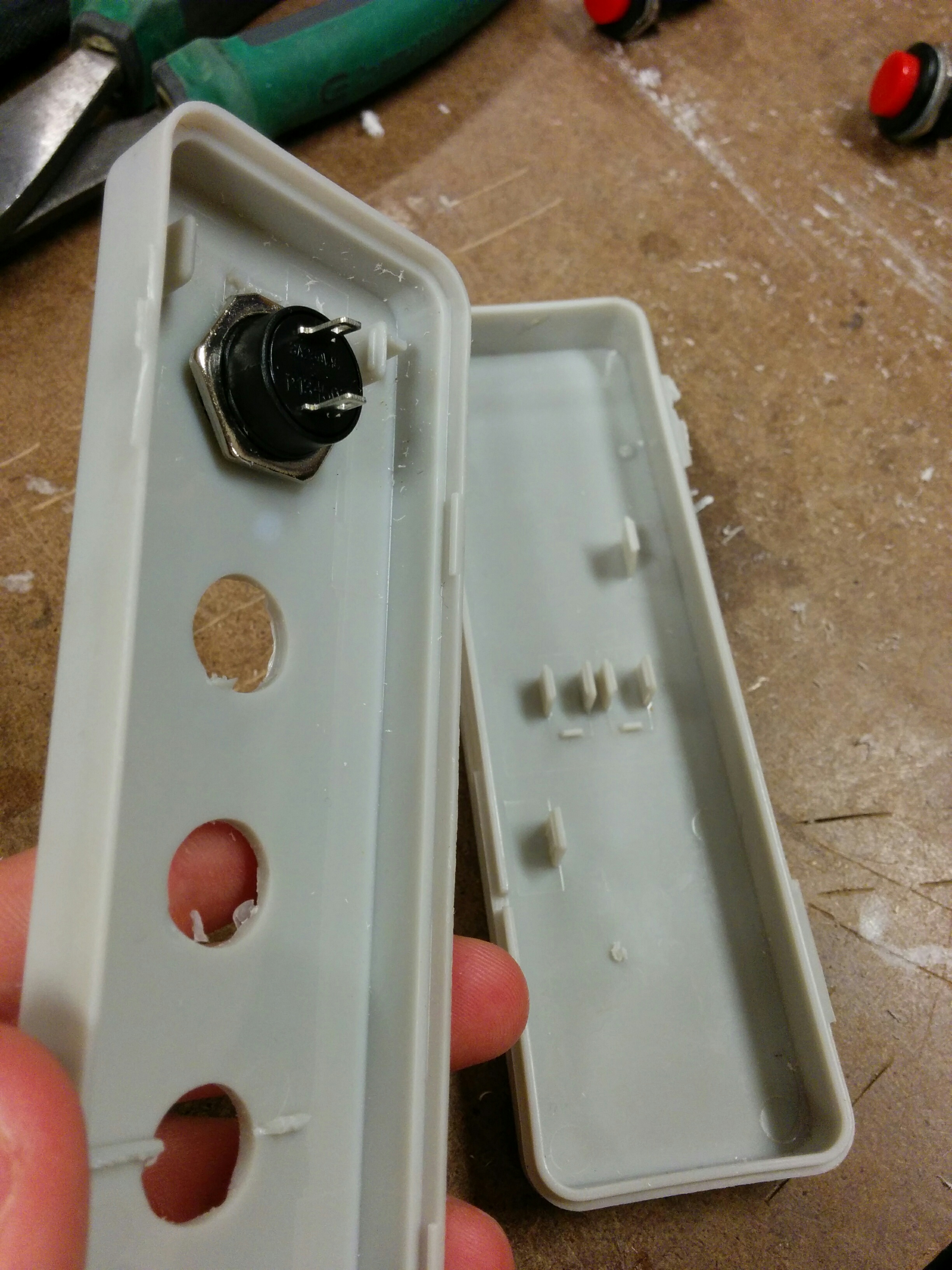
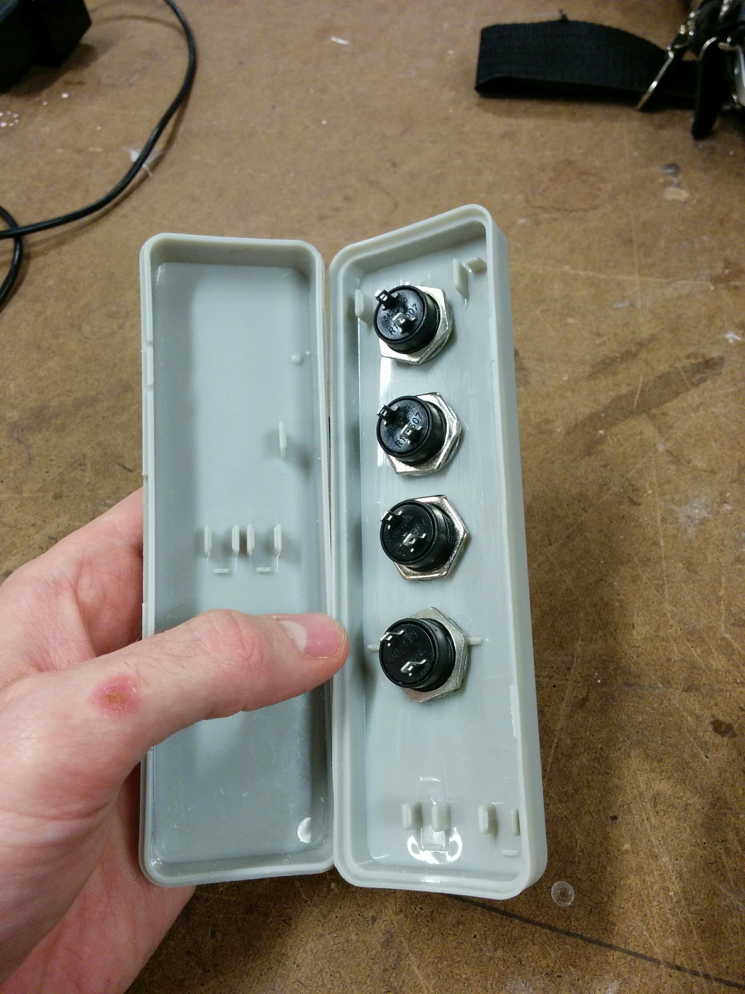
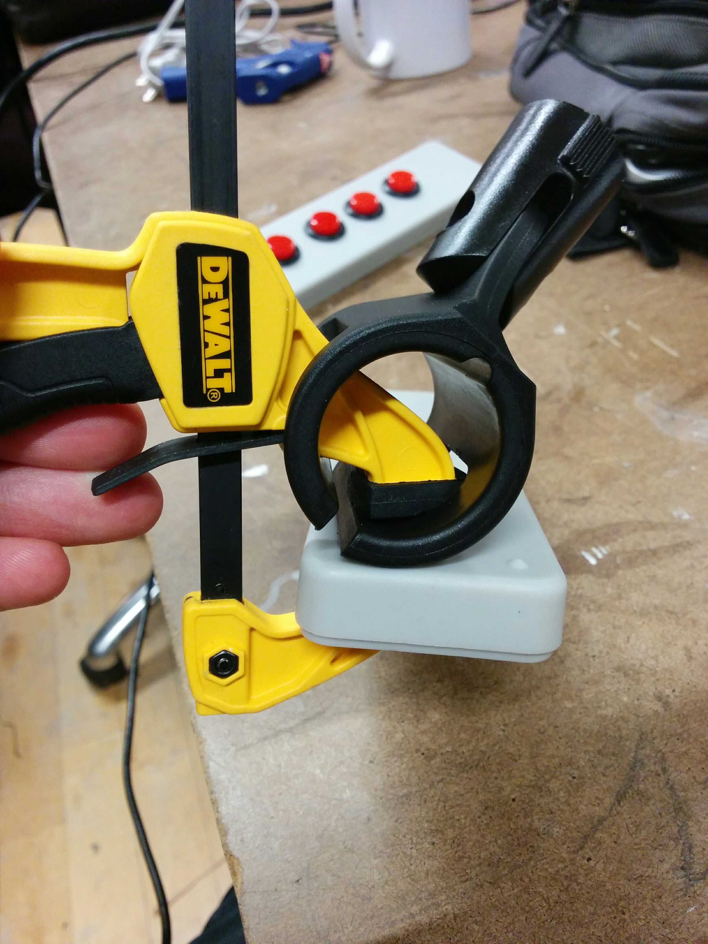
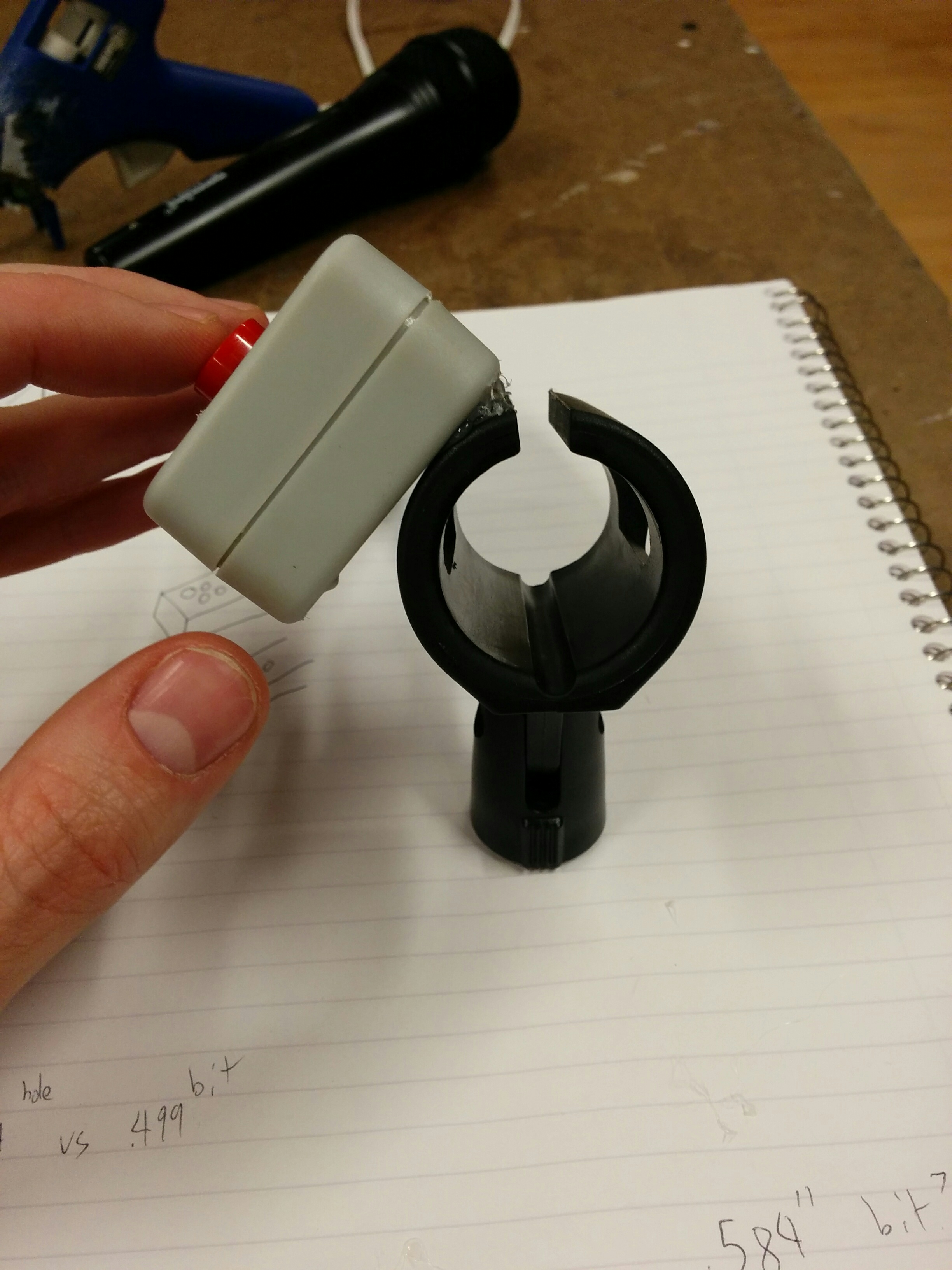
The box had two hinges made of plastic, one broken. Trying to clamp it effectively weren’t going well, and the one good hinge was looking a little flimsy so I just separated the pieces. Made for a much more secure clamp. Also, as you can see from my notes, I could only find a 1/2″ bit in the shop, and nothing larger. Would have to do for now, as John explained that the larger spade bits we have in the shop shouldn’t be used on plastic.
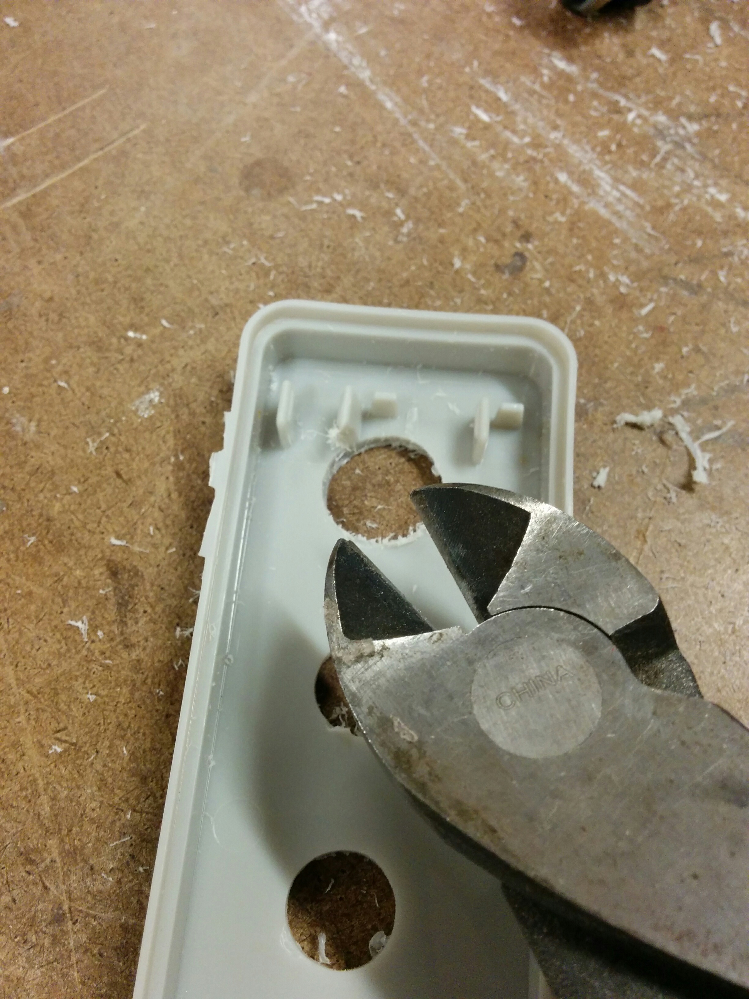
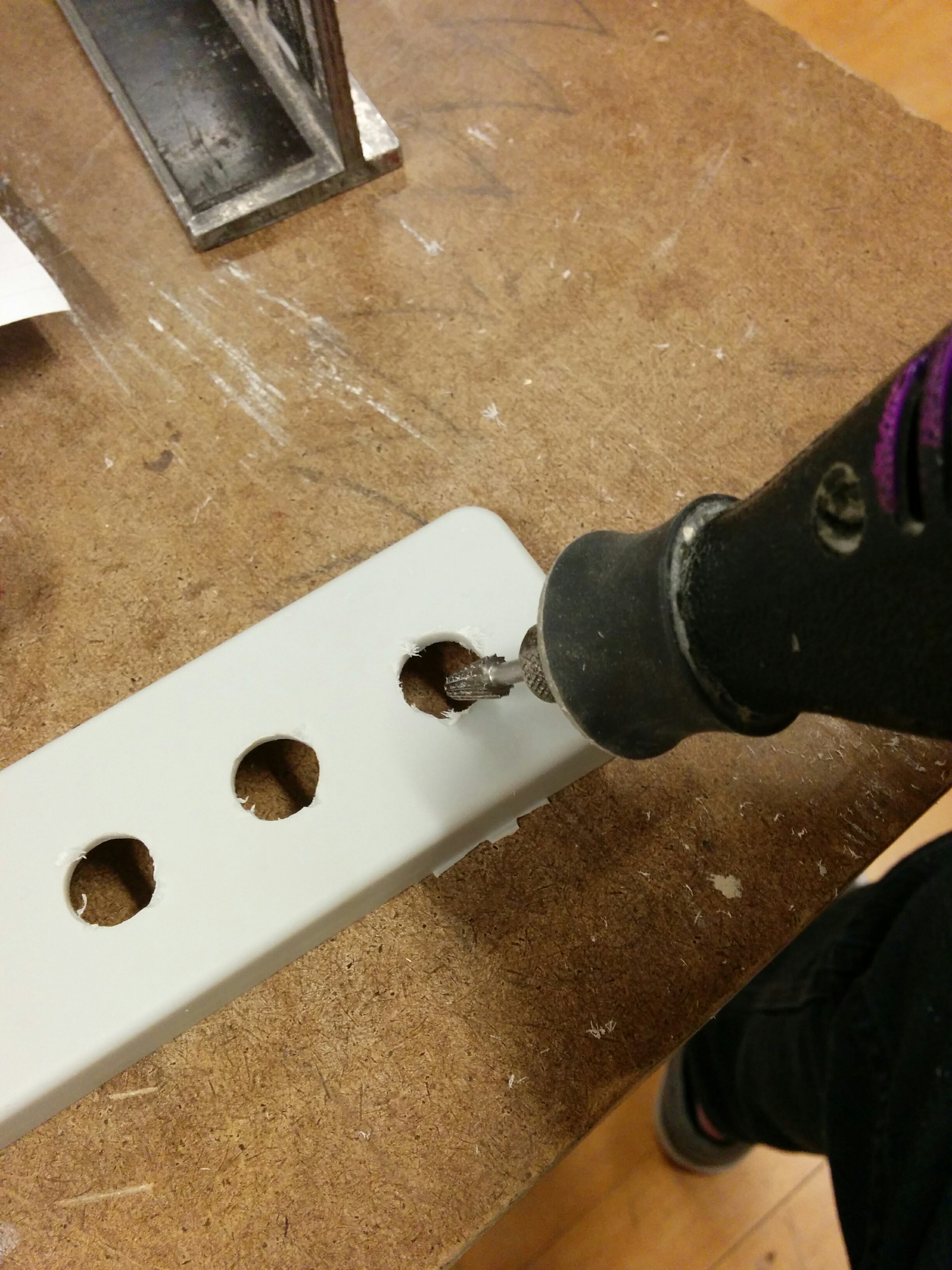
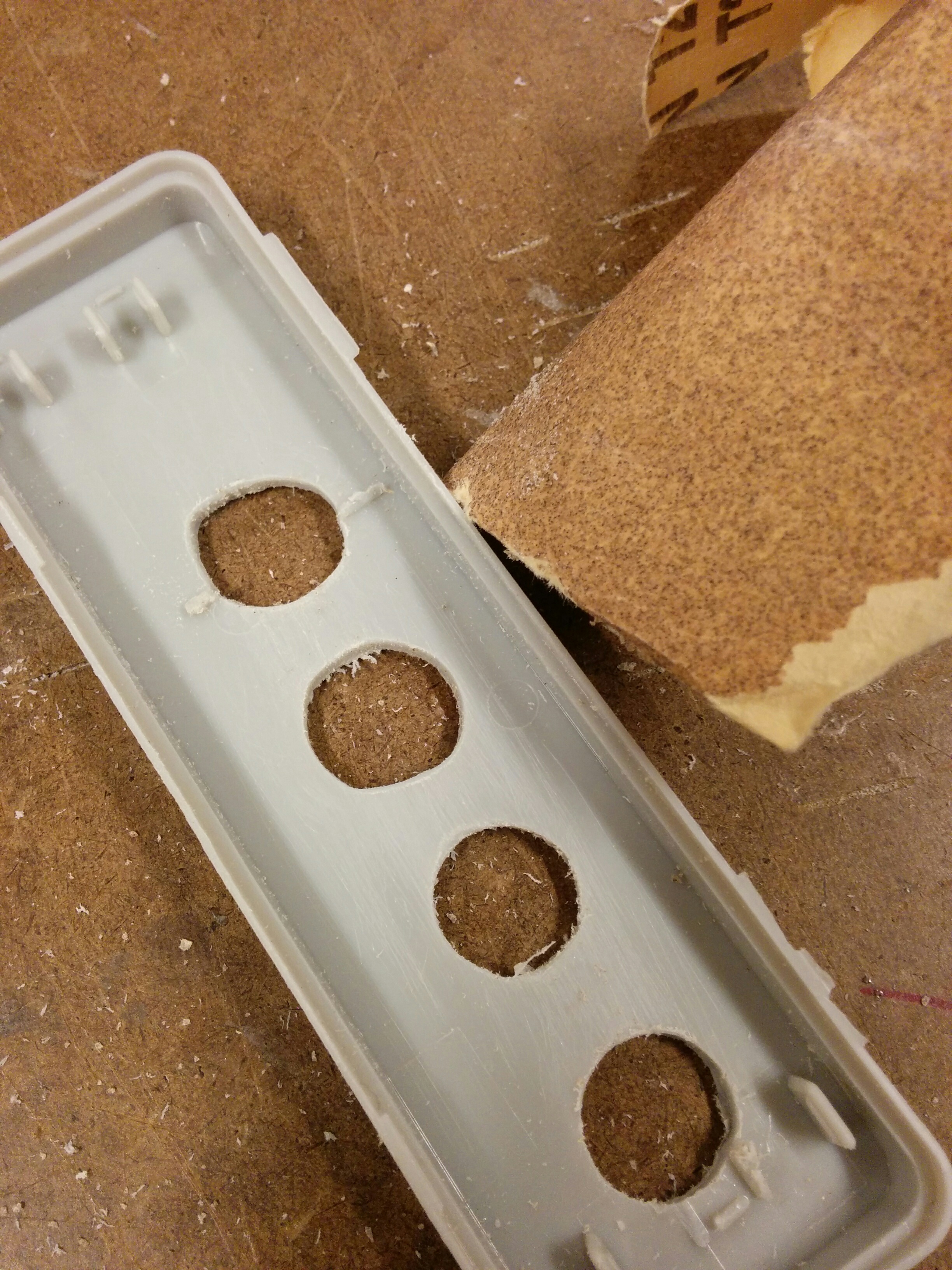
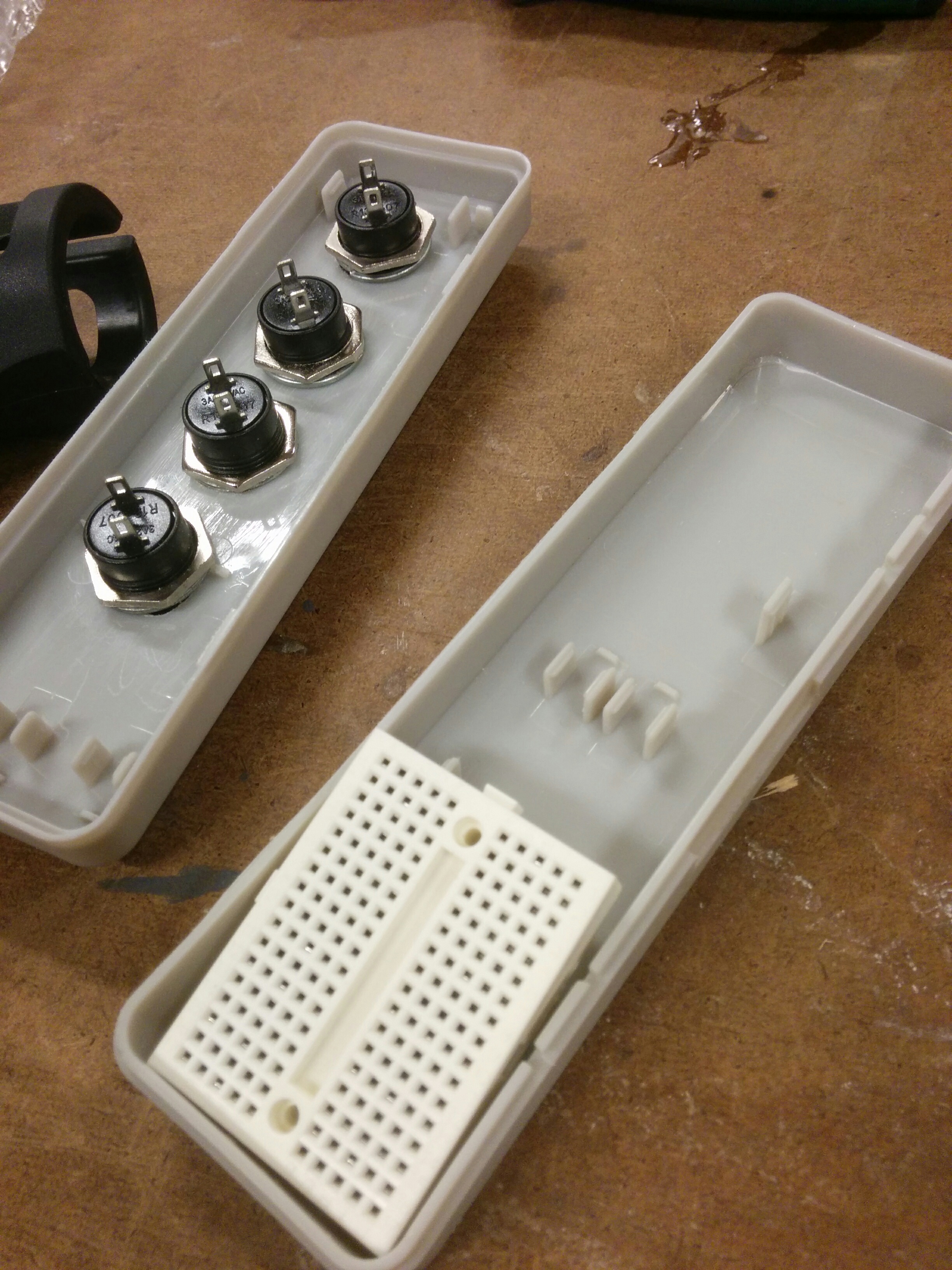
The holes came out alright, but I was hoping that maybe I could just kind of force the buttons in. The plastic turned out to be much more resilient than to allow that. So I cleaned out the inside pieces of the enclosure and started slowly, piece by piece, expanding one of the holes with the Dremel.
It was more Dremeling than I thought I would have to do. You can pretty clearly see the hole size difference with the naked eye. It wasn’t too bad, but if I was making multiples this is where I would be kicking myself and/or going on a quest for the perfect bit.
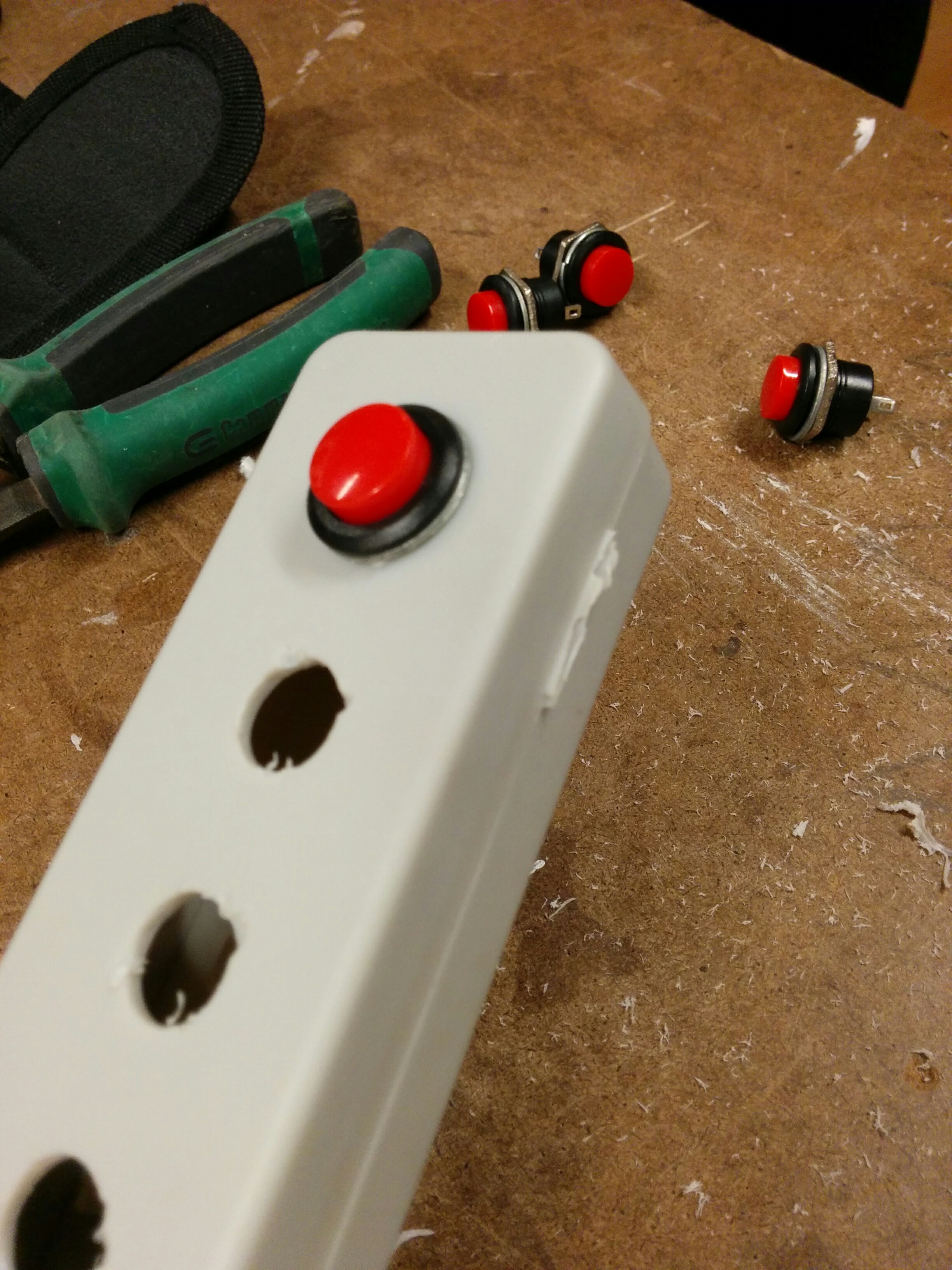
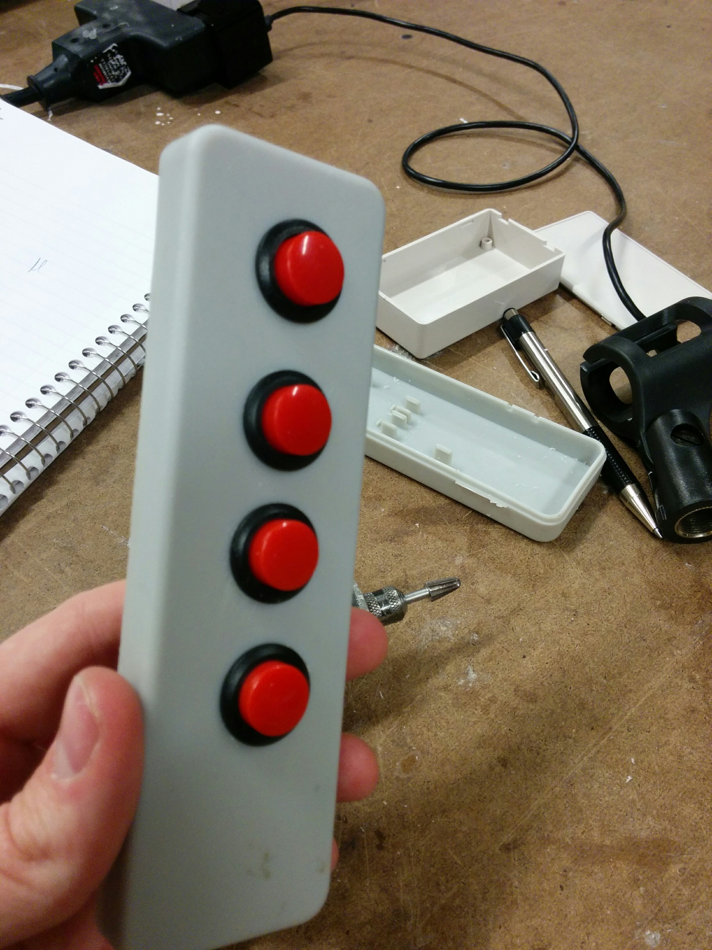
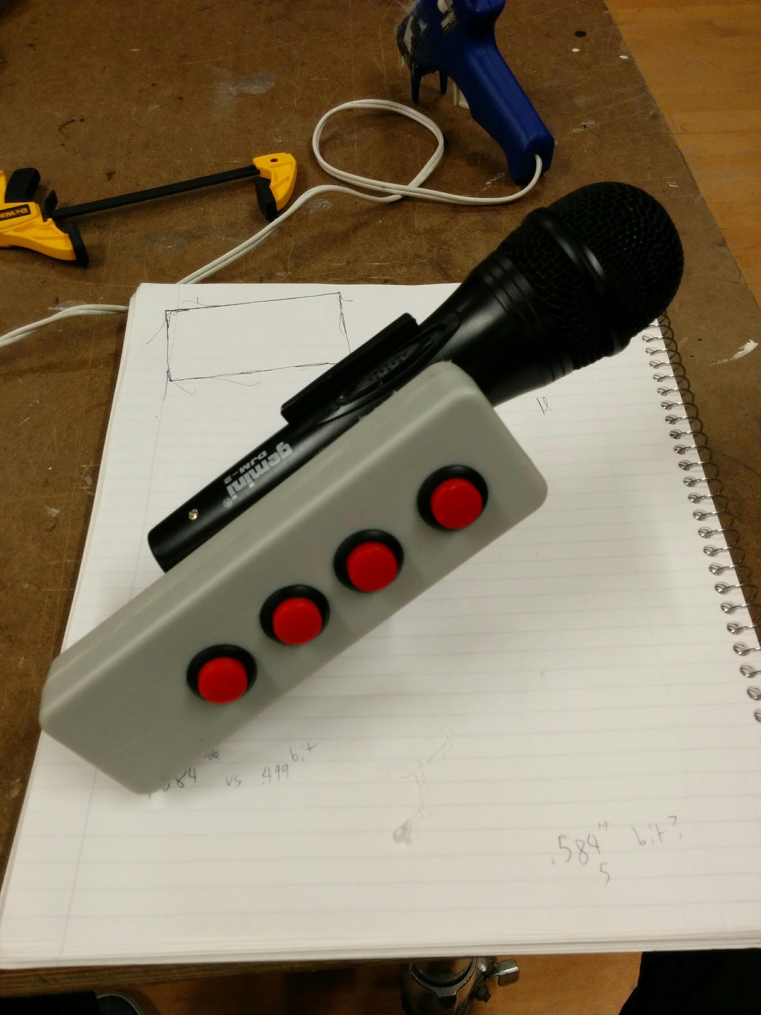
Which is even more apparent when you look at the end result. After trying to keep an even hand, slowly testing the button and returning to the Dremel, then sanding out the end results, some of the holes were looking… interesting.
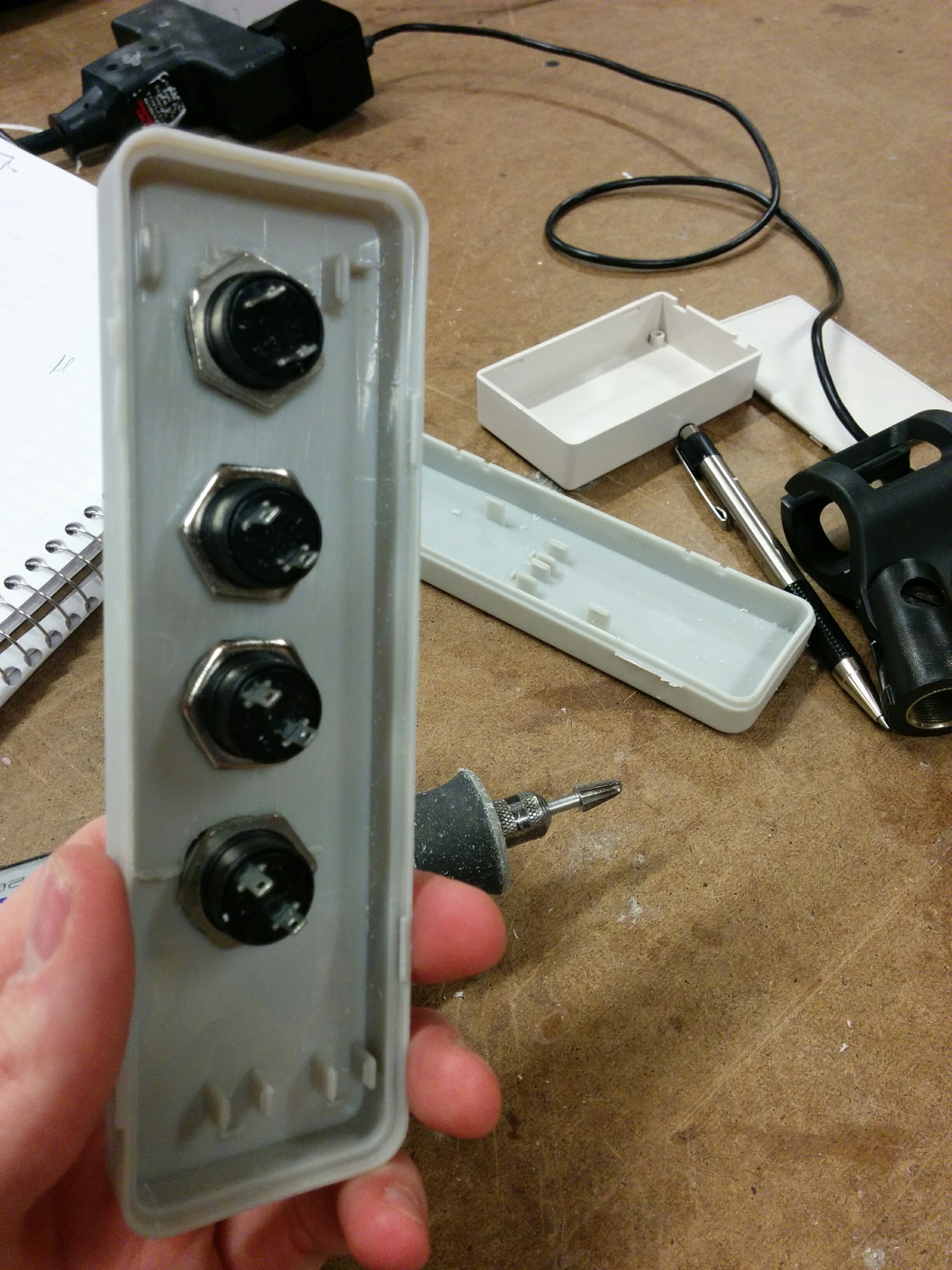
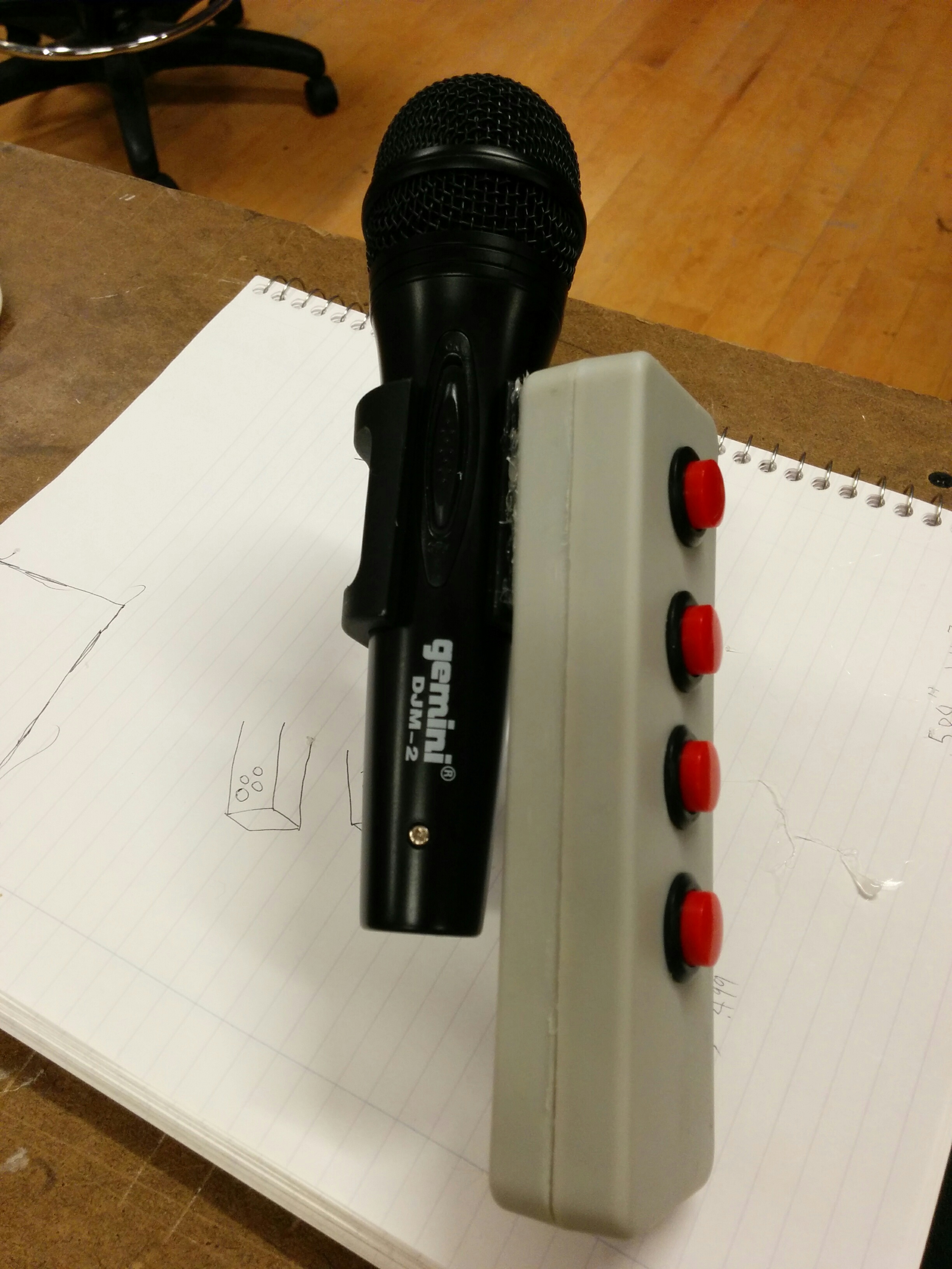
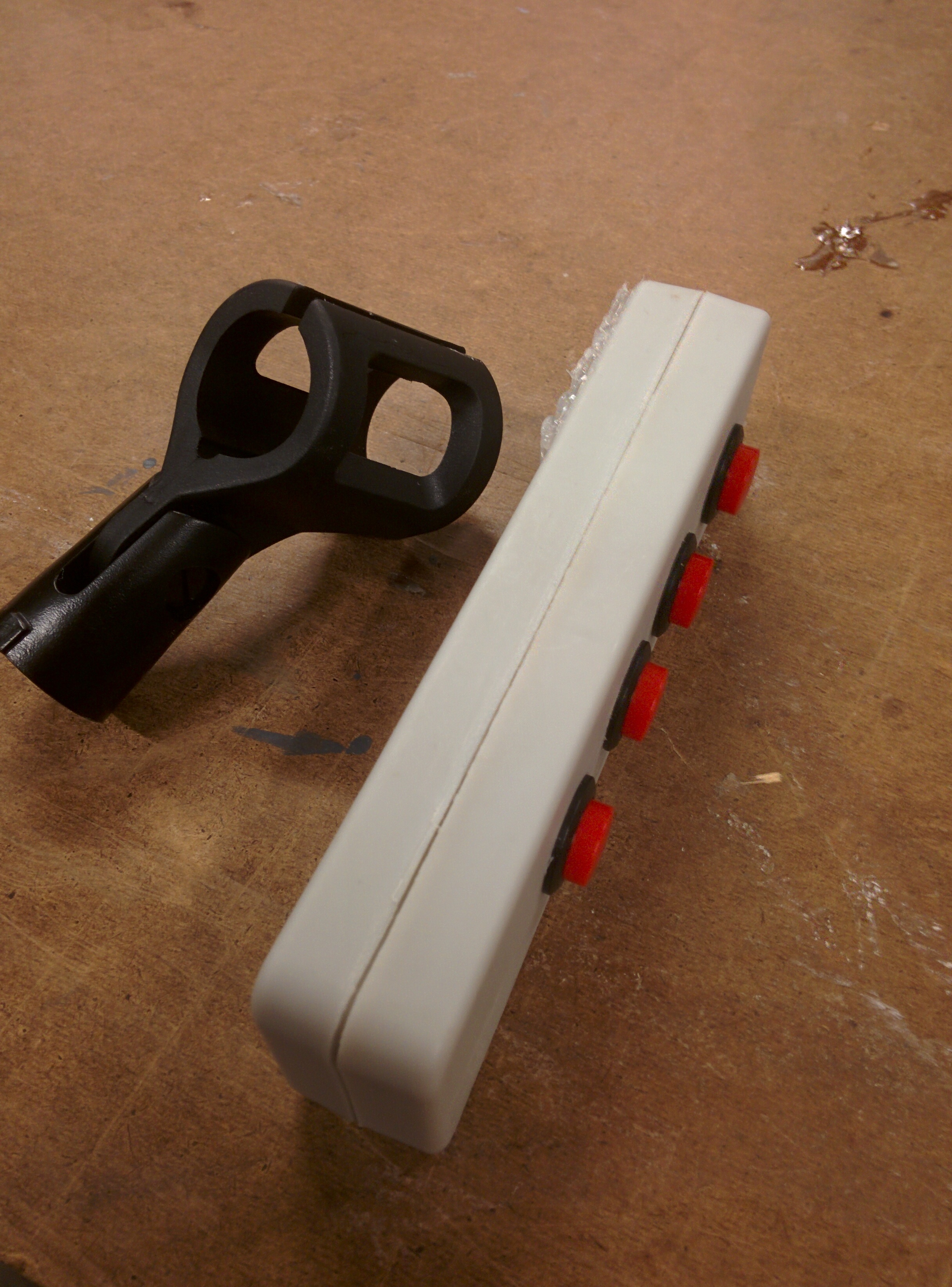
However ugly, they were effective. Constantly testing them made sure that the buttons fit as tightly as possible.
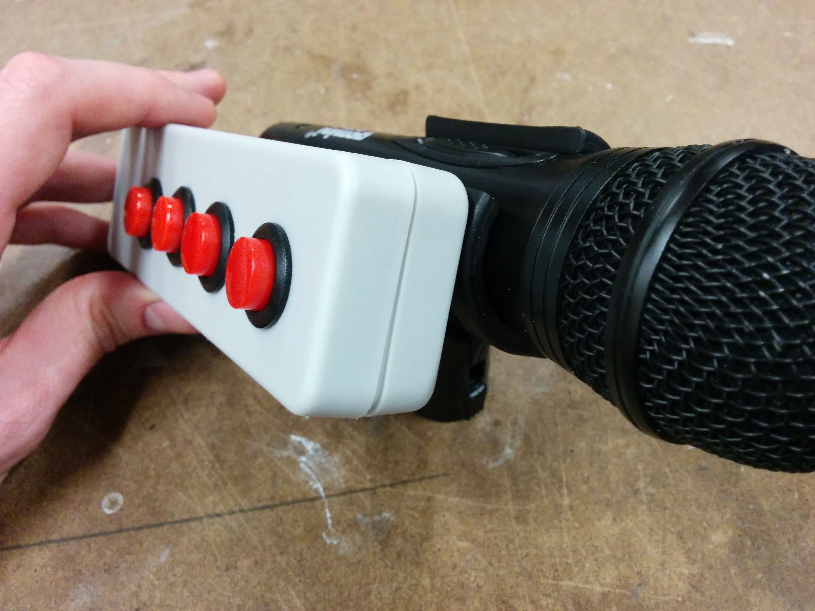
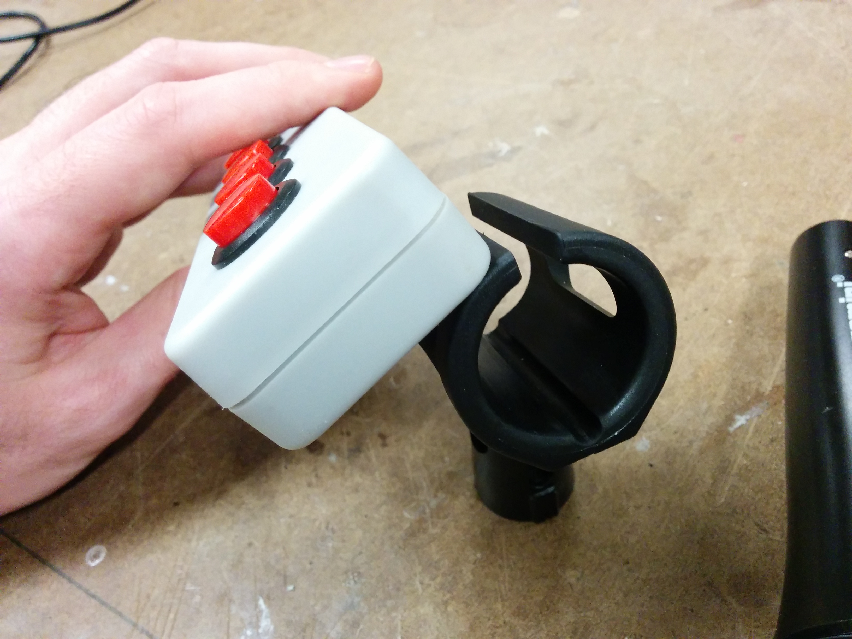
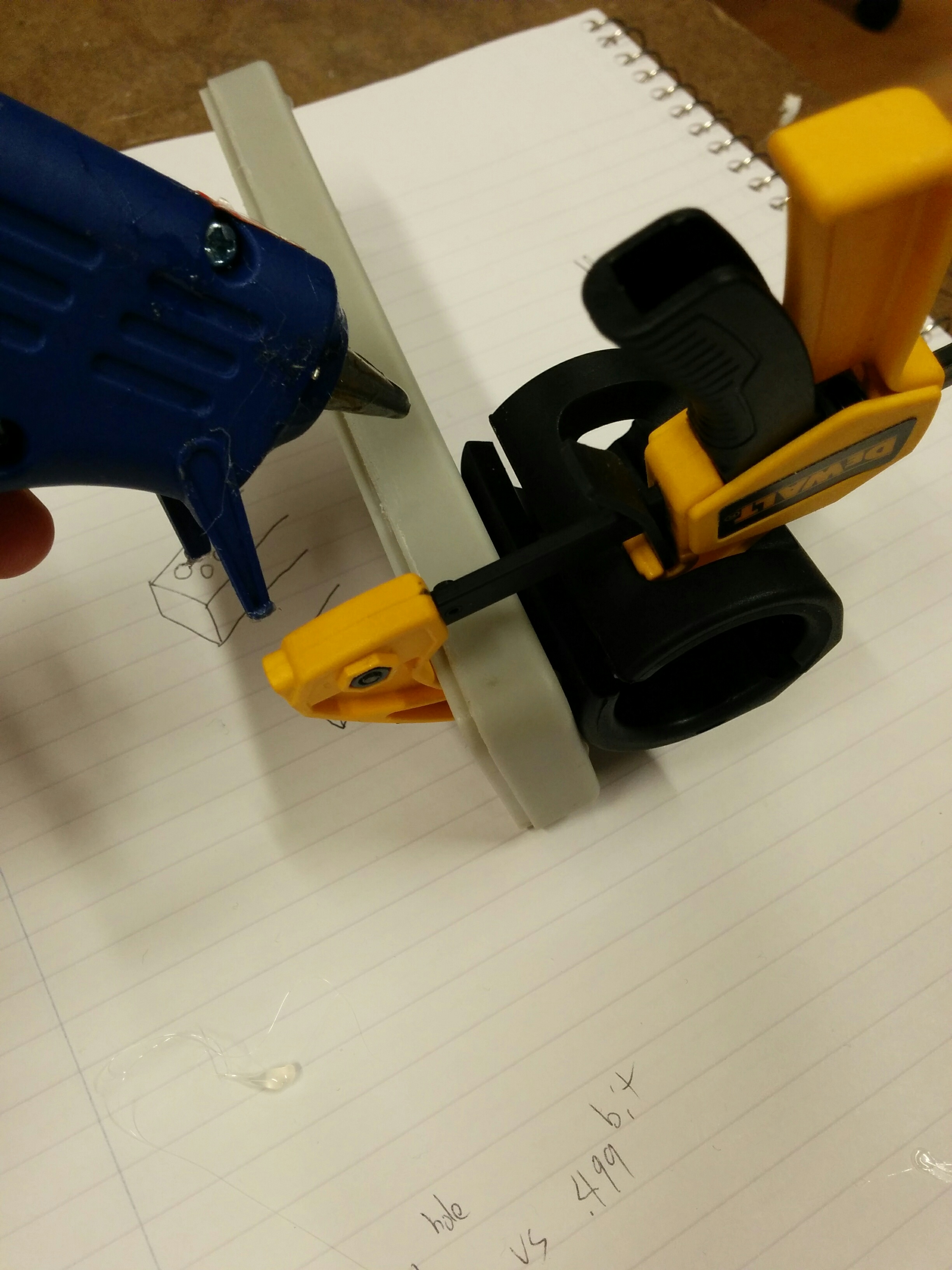
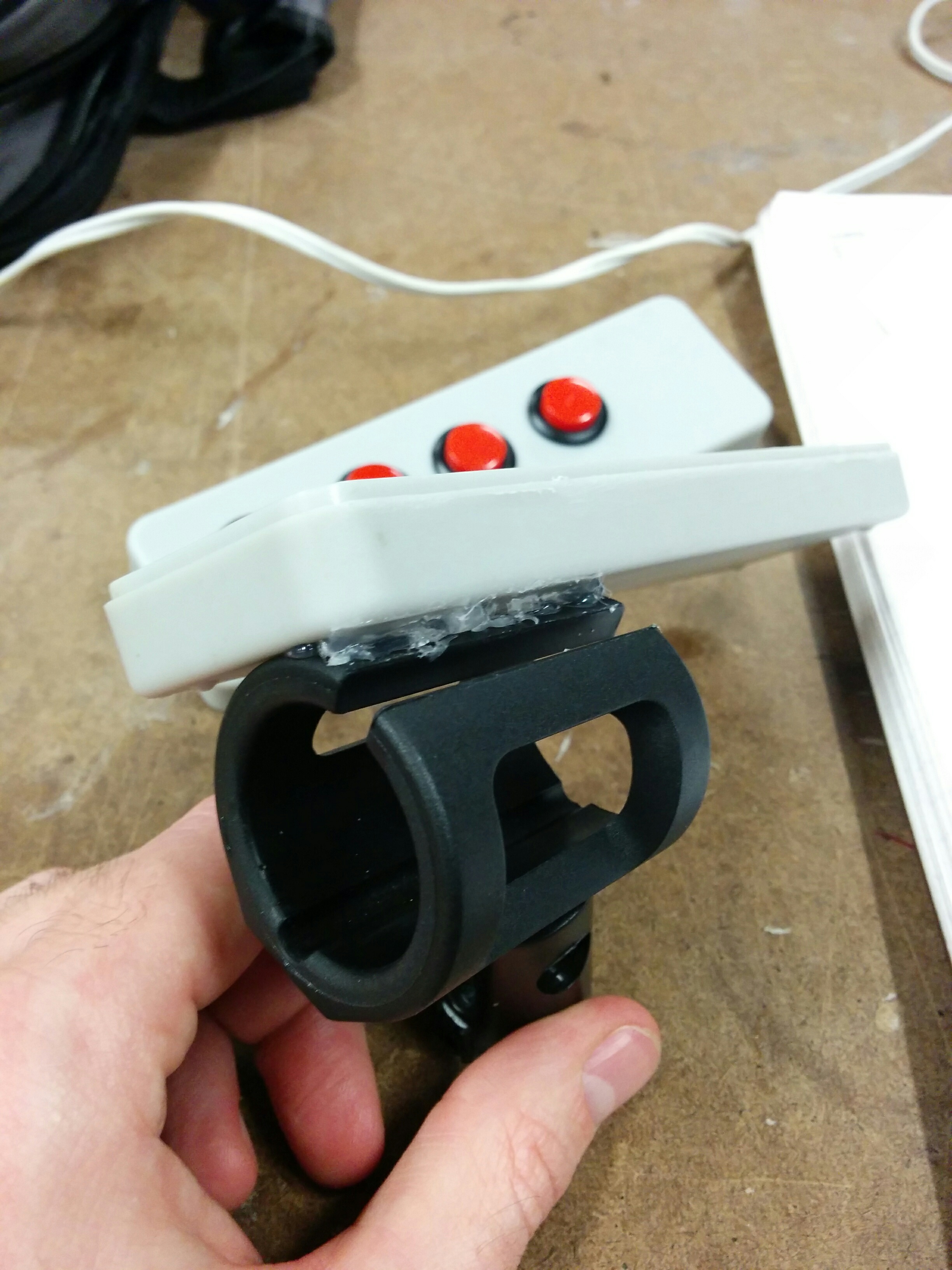
Putting this up against the mic clip, I was happy that I started walking before I ran. Going with a more straightforward box now feels like a wiser choice when considering how things can and will change over my prototyping process. But I wasn’t sure of the best way to properly attach them together. Because of the nature of the clip, which expands as mics are inserted and is tightly flush against the surface of the mic neck, there were many approaches that I would normally take that were off the table.
Not entirely sure where to turn… I went with plain ol’ hot glue.
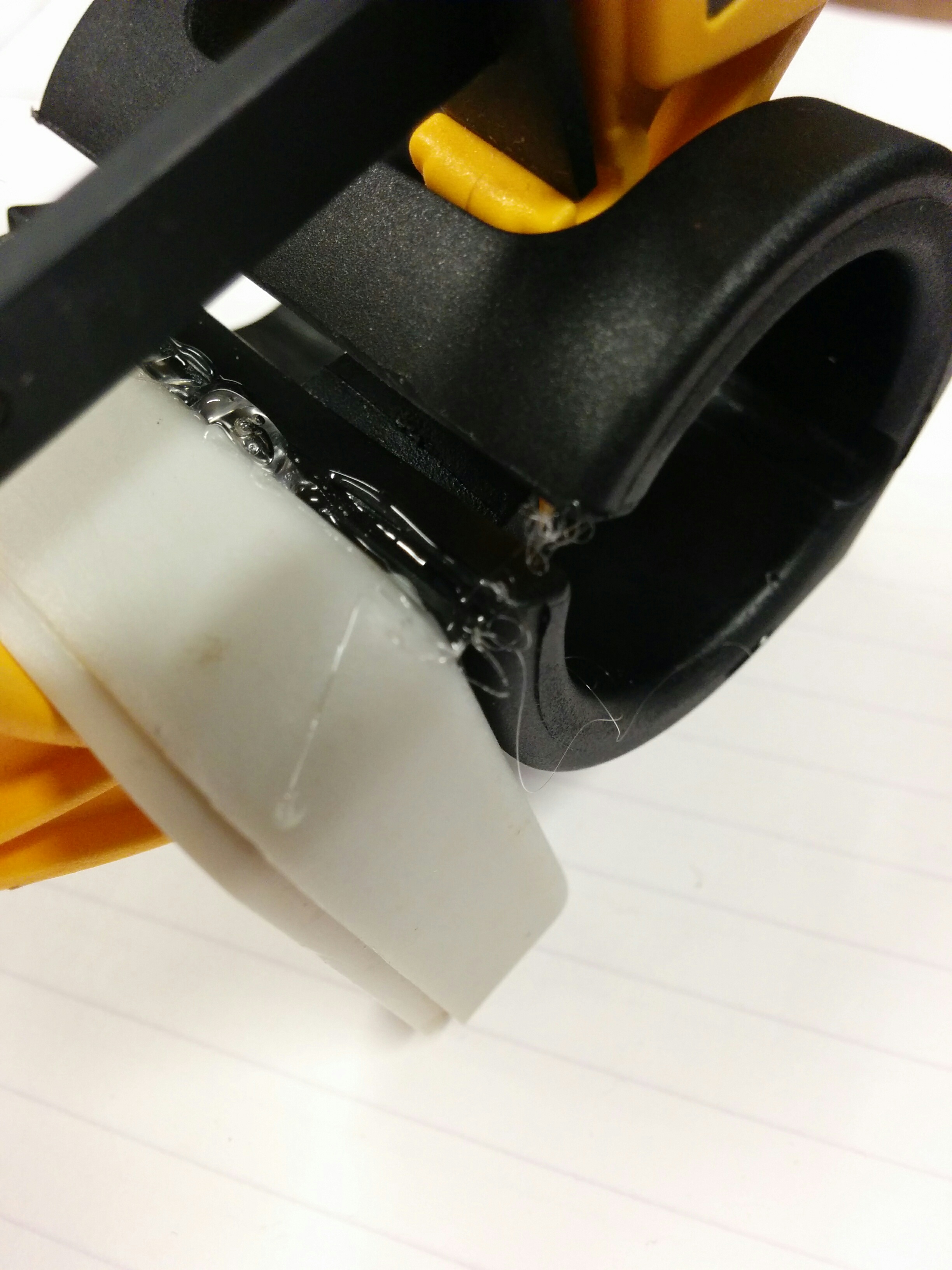
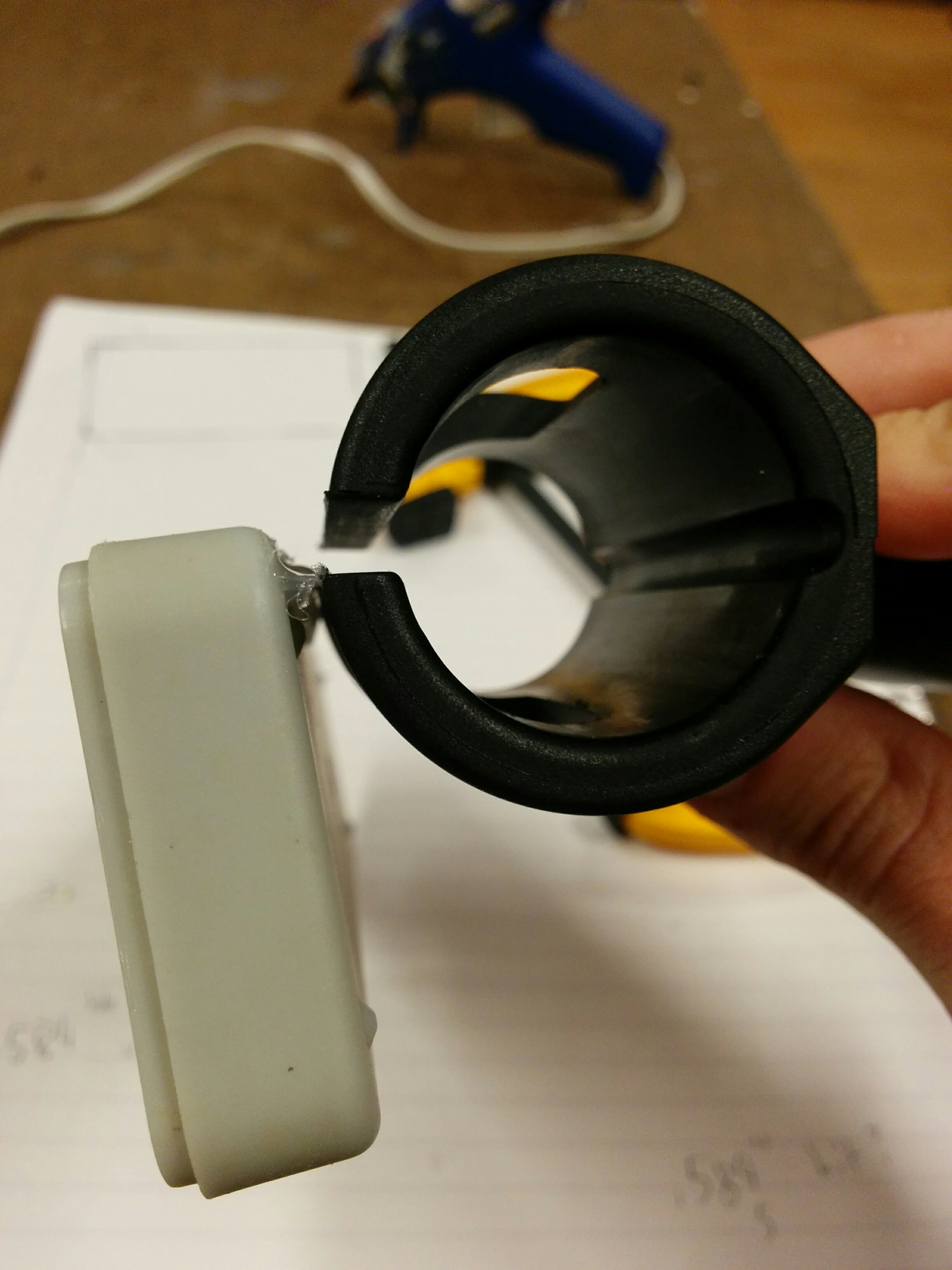
Hot glue. It’s like this totally normal thing that people use all the time, right? Wow can it get messy quick. One day I would like to get some tutoring on elegant hot glue technique (if such a thing exists). Luckily, it was easy enough to pull away the fine strands and peel off the egregious errors where necessary. I wound up with somewhat of a loose hinge:
Then with that I was able to do a second round that covered more surface area and adhered solidly.
Yeesh! These glue strands get everywhere. But after some cleaning up I wound up with something fairly sturdy:
That is where I’ve left off for now. I have some parts coming in, and depending on specifics might change the focus of the rest of this assignment. It could make sense to just keep it more or less looking the way it is and hook it up to my microcontroller once I get all the parts, and keep this as a version 1.0 functional prototype. However, despite it’s early 80’s beige/gray charm, there is a part of me that would like to make this look a bit more presentable. Updates will soon follow.
Part 2
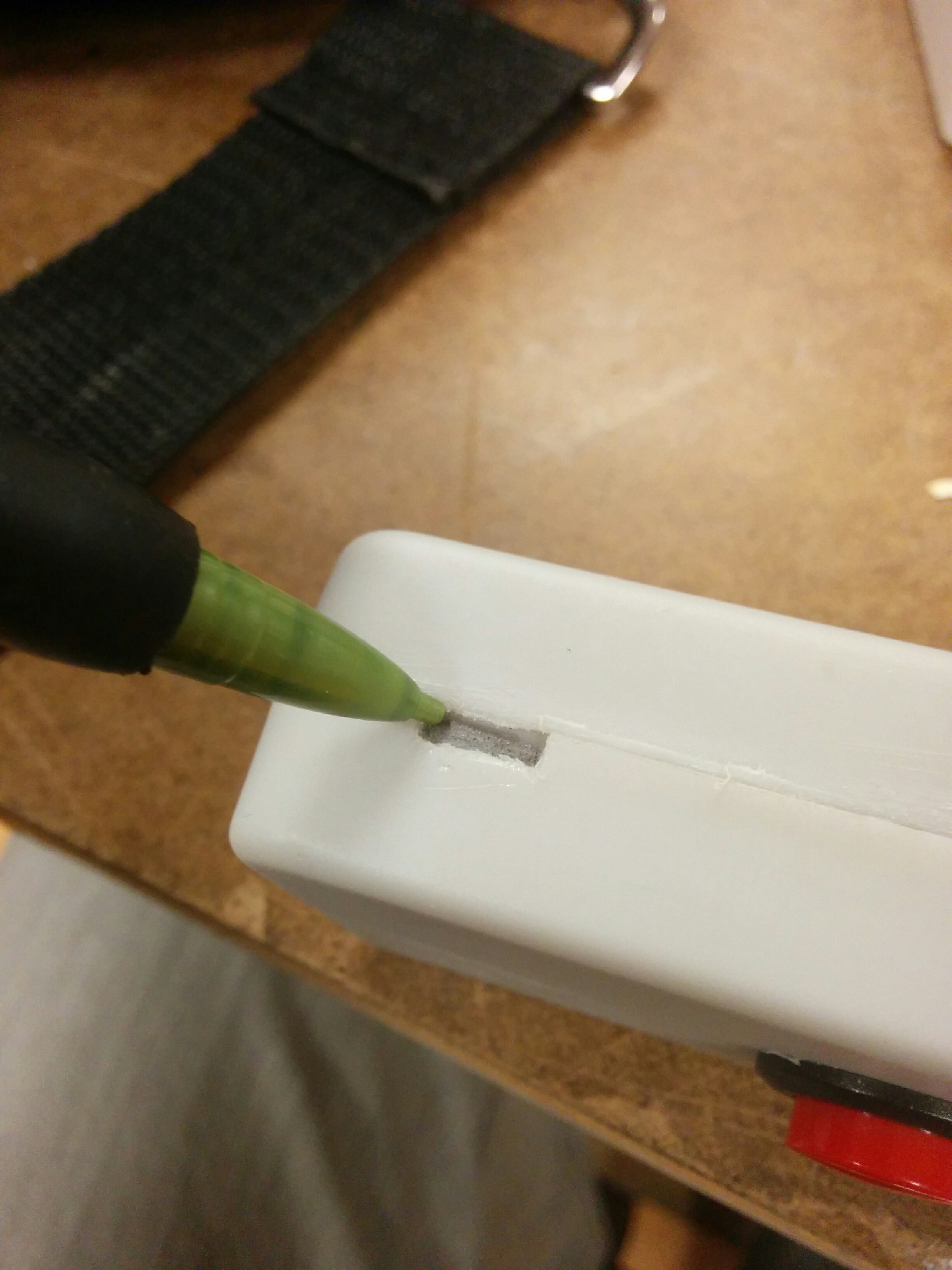
Having some issues uploading my images, but I will do so as soon as my internet connection gets a little better. In the meantime, I have added a little slot for my microcontroller to sit inside of the enclosure. There were some other issues, but I’ve got some decent end results to share. More updates tonight and tomorrow!
The first dissapointment I had upon returning to my project was that the hot glue did not hold. Not sure if this was due to being bumped (it was in my open project box), or otherwise.
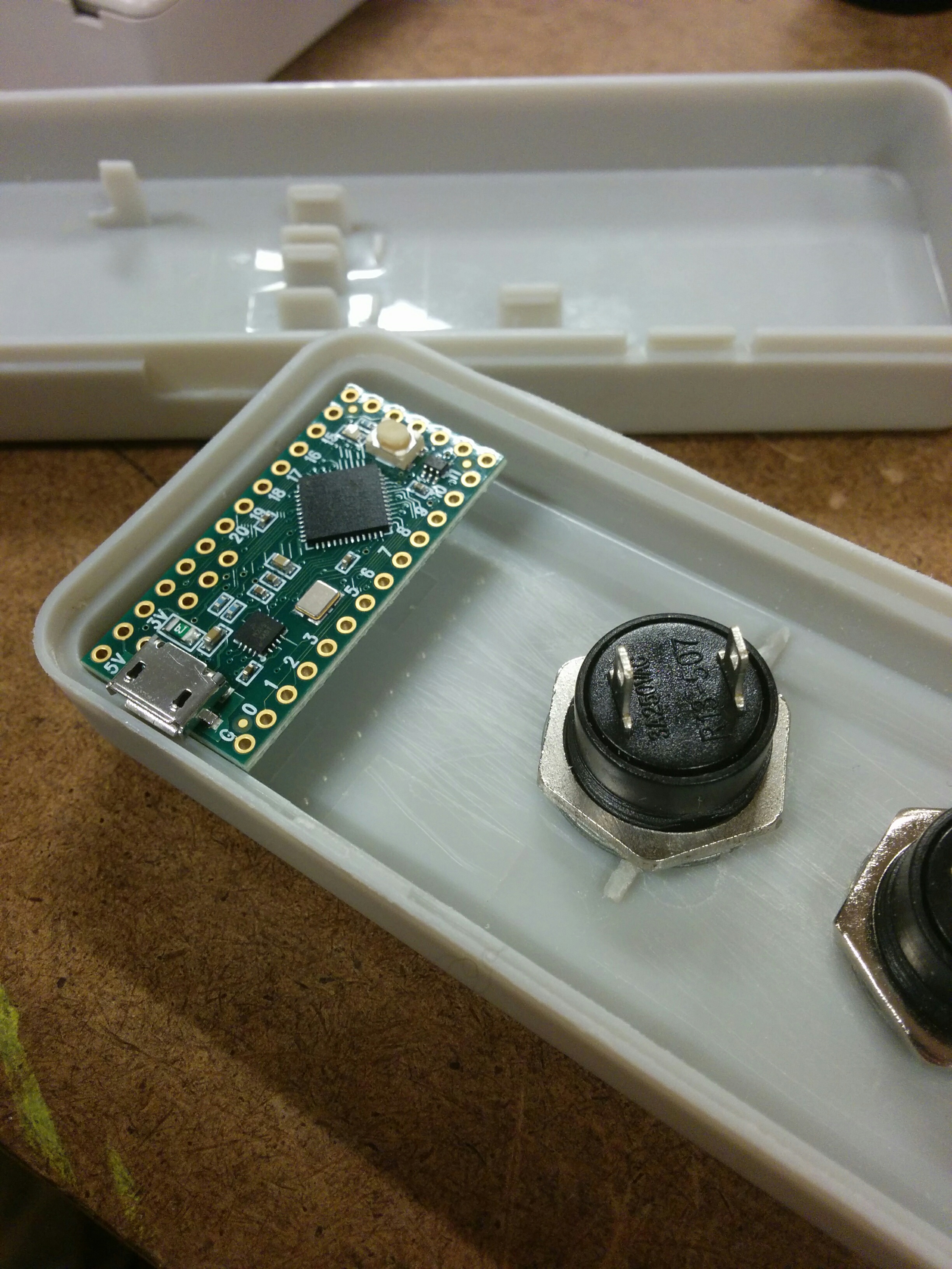
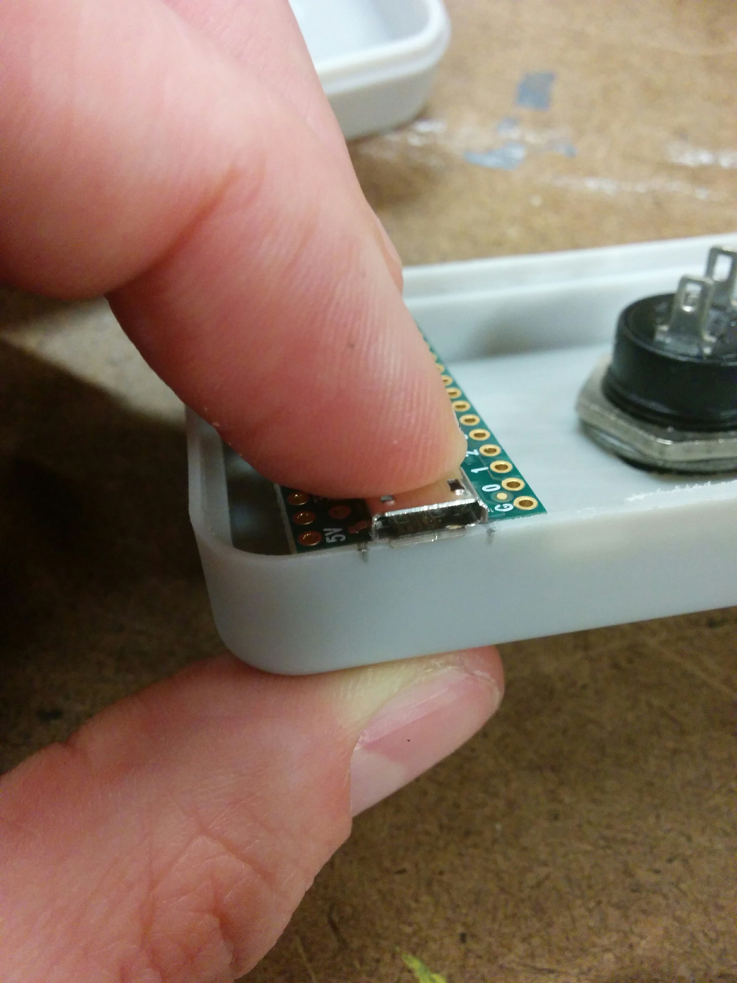
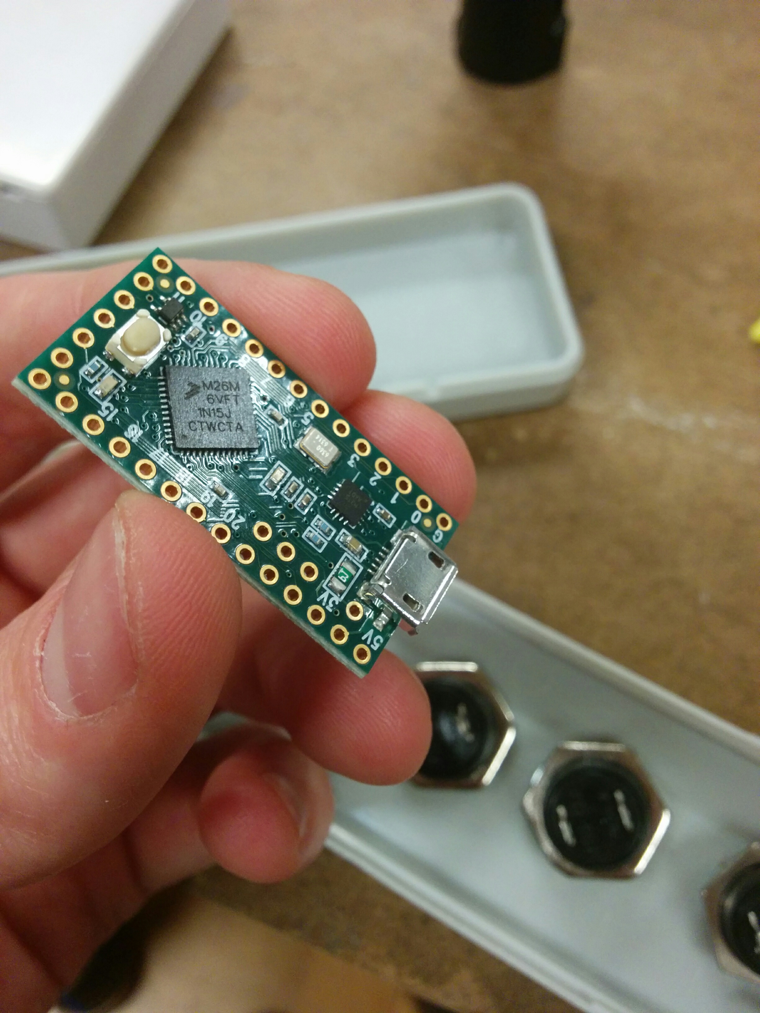
But it was an opportunity to make the work a little easier to handle. I received the microcrontroller I need for my Physical Computing class, the Teensy LC.
But there are no mounting holes on the board! I hadn’t accounted for this when I originally ordered, but it removed the option of using standoffs as a mounting solution.
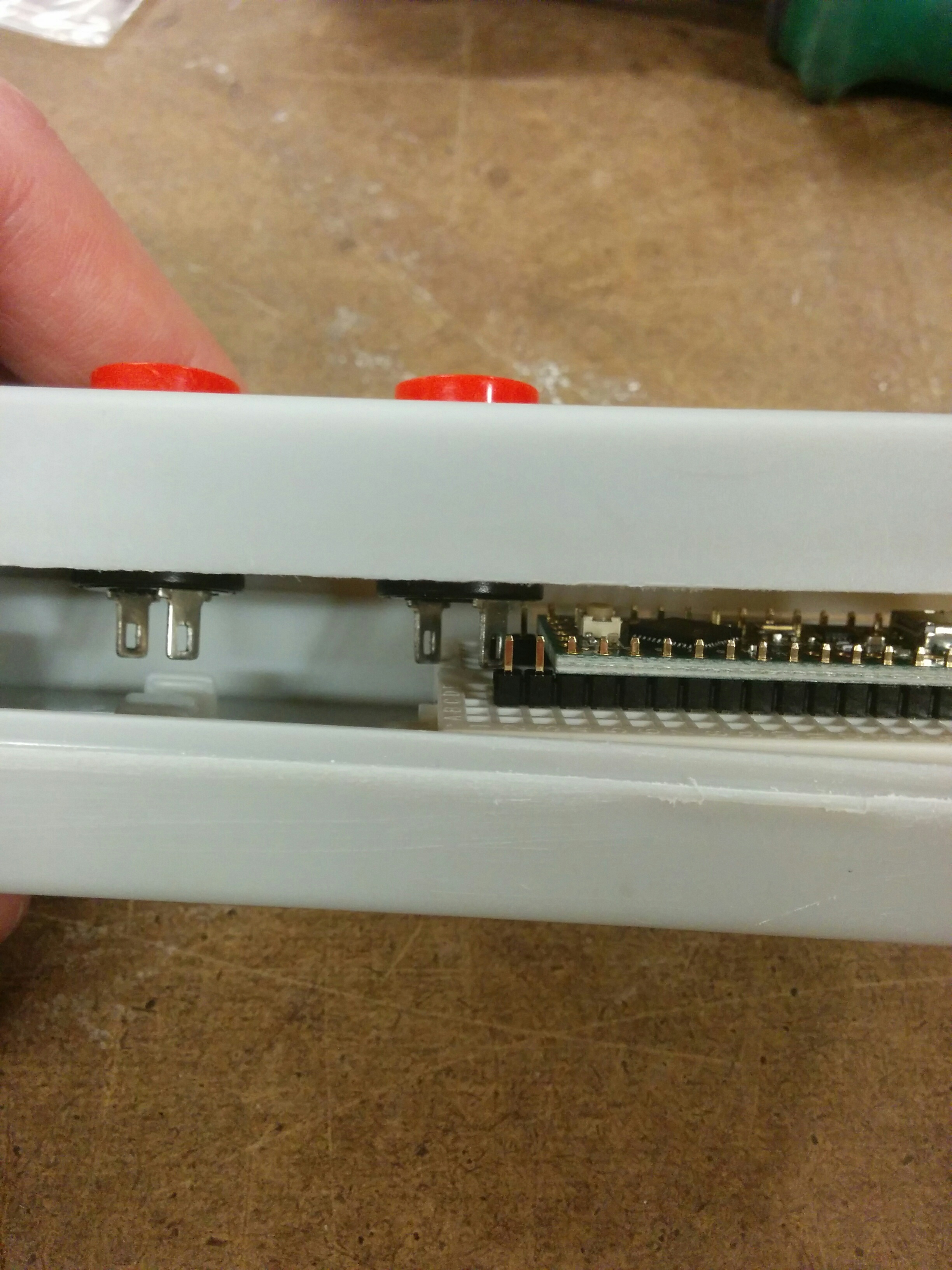
I started clearing out space in the enclosure in order to hold a bread board, which fit *just* perfectly…
Until I put the board onto the bread board and saw I didn’t have enough clearance. The last button was getting in the way.
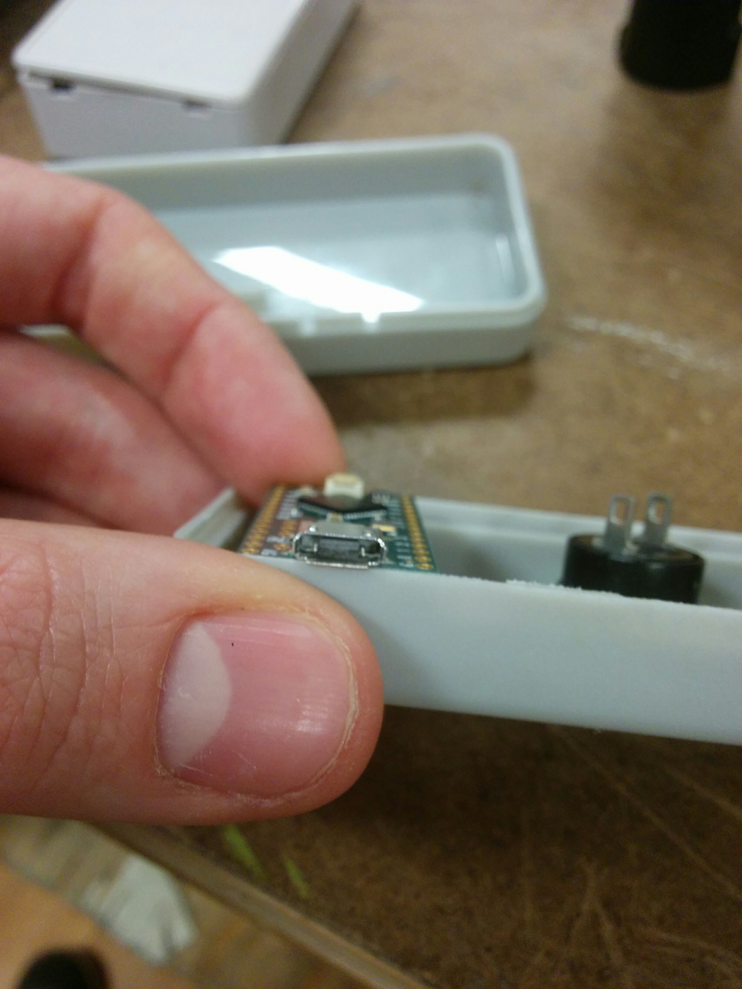
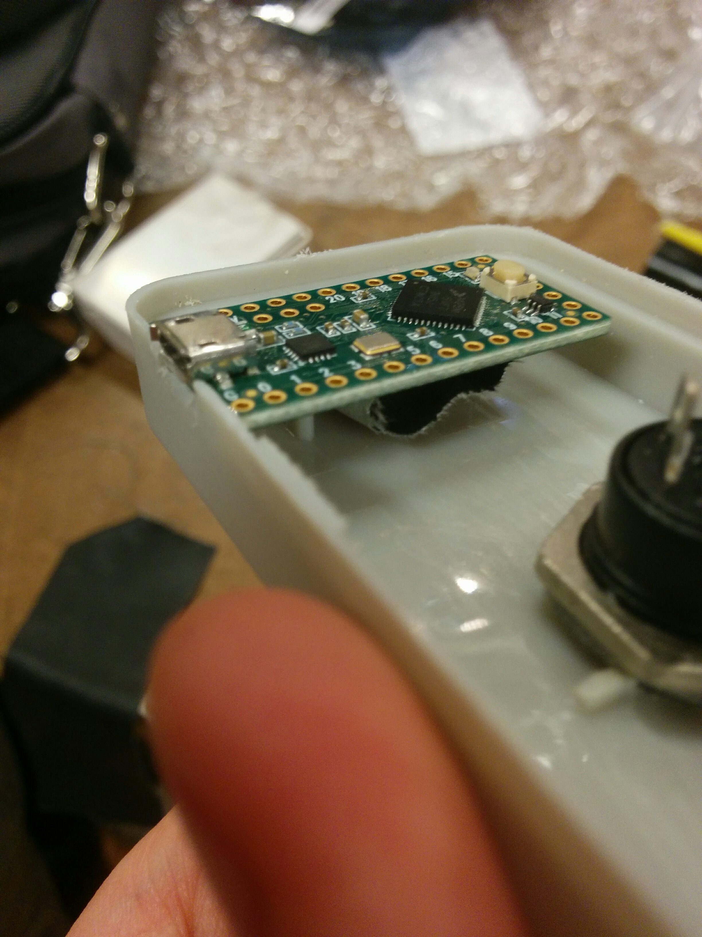
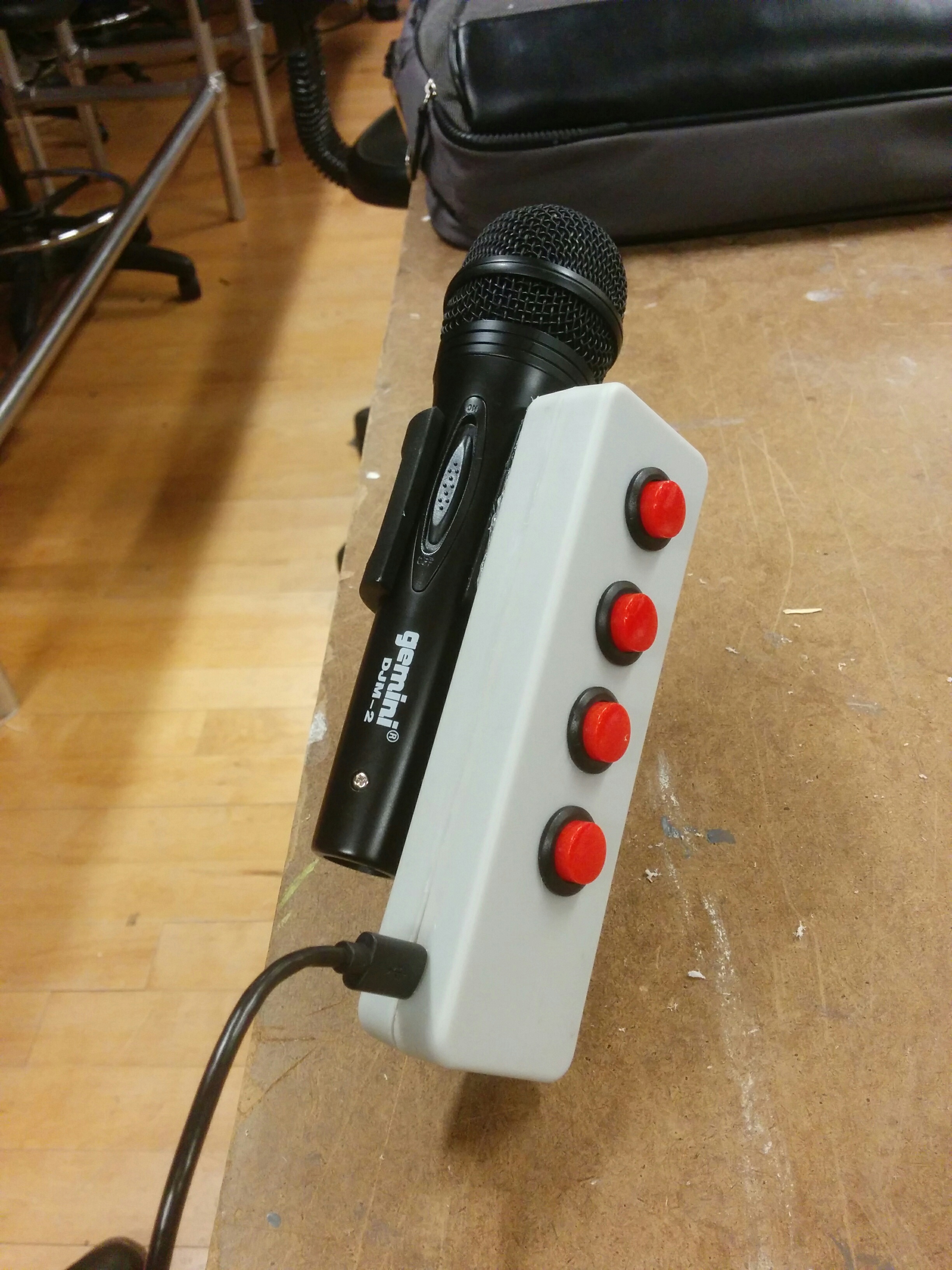
I started playing around with placing the board onto the plastic nibs that were inside of the enclosure to start.
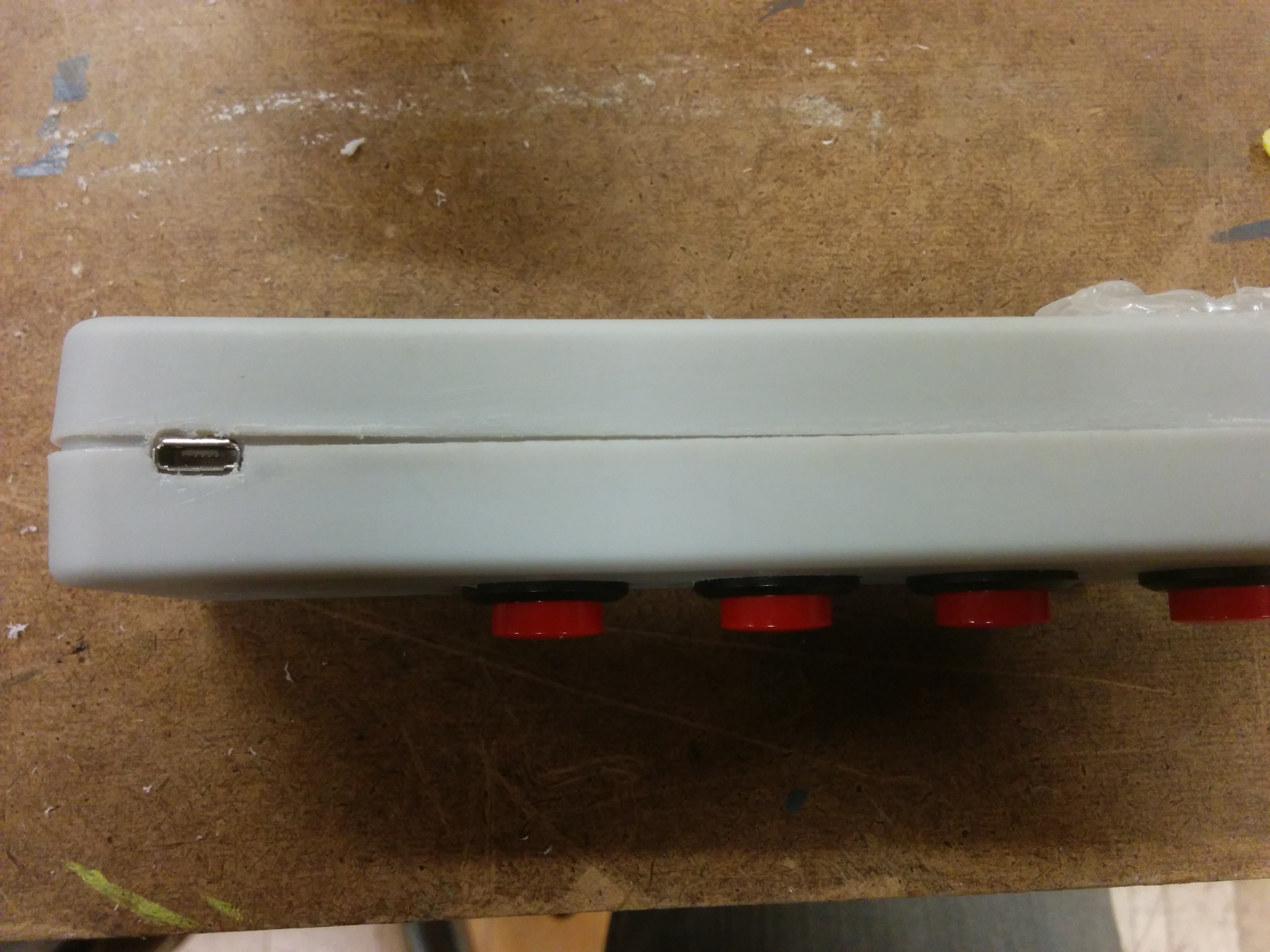
It isn’t very pretty right now, but I think for my initial functional play testing this can serve its purpose. Next step was to re-glue and attach a cable.
Once I had gone all in on my enclosure choice, it made it a little difficult to go back. But I think after this assignment I’m definitely going to re-asses my options. For my playtesting, I might wind up kind of hacking this thing apart into something resembling less of a traditional enclosure for the sake of being able to re-wire and re-position things quickly. But I certainly learned plenty about what was possible in terms of pre-made enclosures and will feel comfortable about going to the drill press to quickly produce little homes for my projects.
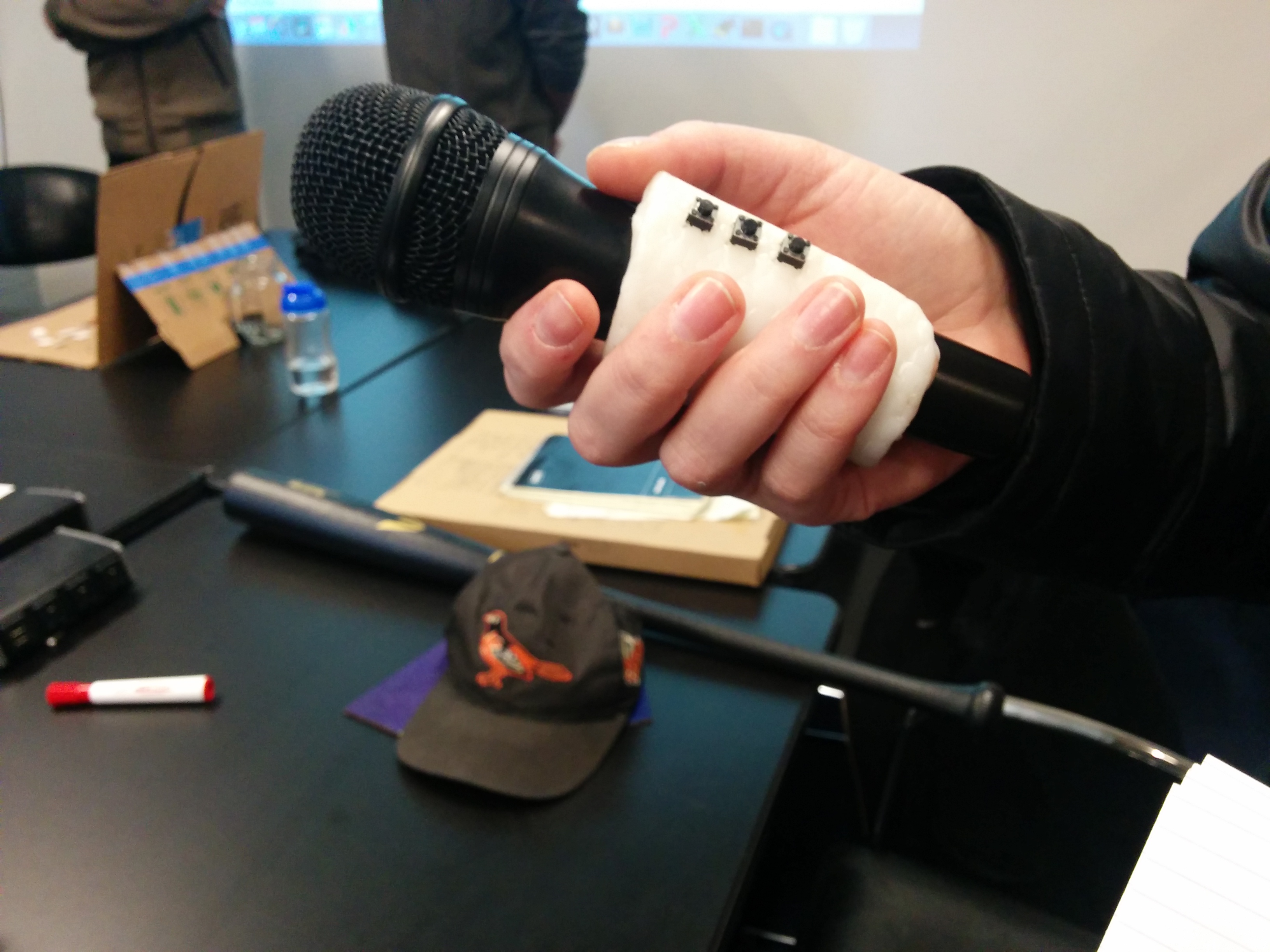
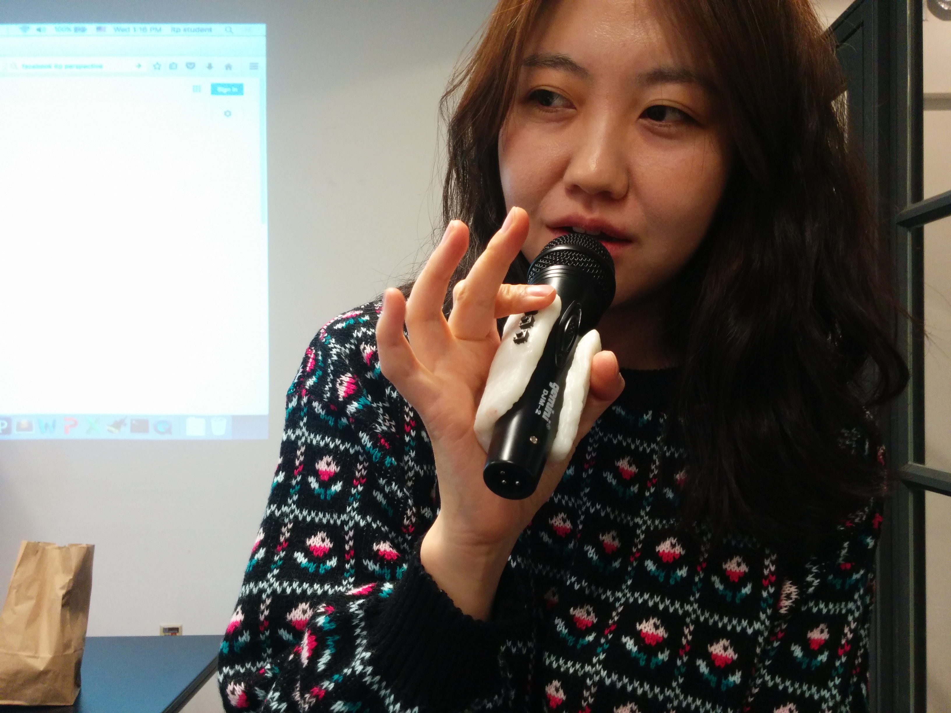
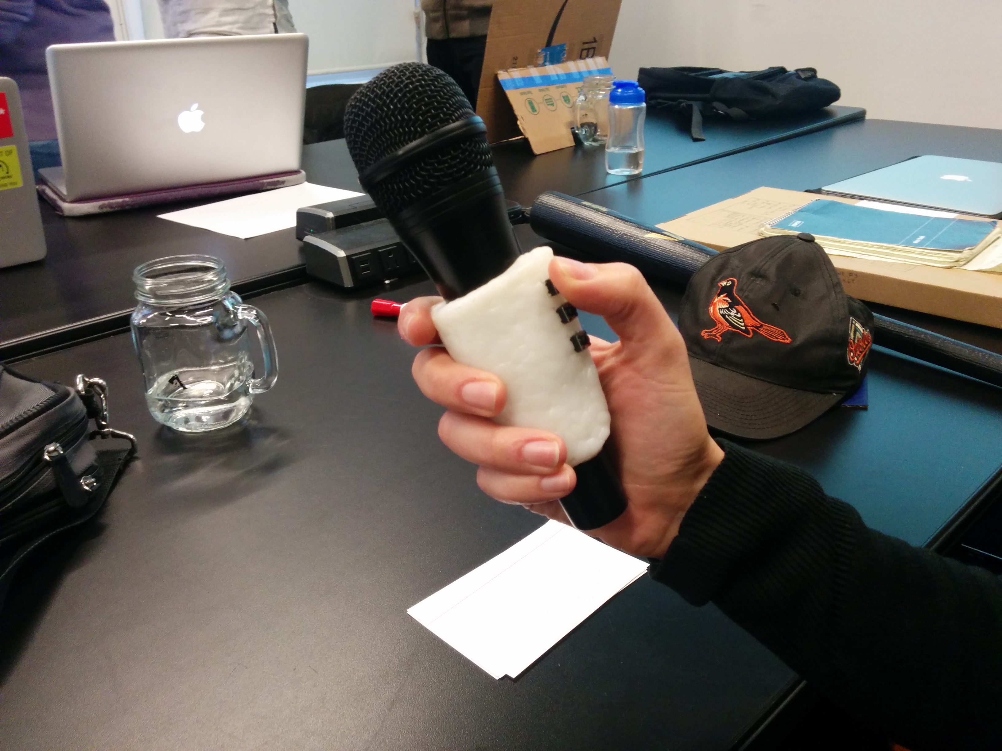
After presenting my initial concept to the class, my next step was to create a playtesting prototype. I felt fairly confident that I knew what it would feel like in my hand, but it really did help to have something in my hand. This was made from prototype plastic. After warming it up, I flattened it out like a pancake. Then I wrapped a microphone in saran wrap, then wrapped the prototype plastic around the microphone. I put it into the freezer to harden, and then used a dremel to generally trim the shape. Once satisfactory, I warmed up the piece again, just soft enough to be able to push some push buttons securely into it’s surface.
I used this as a conversation piece when conducting user interviews. I went to the Tisch performing studies floor to talk to different artists about the possibilities of using this device, and what features they might want or wish for it. While there were some wonderfully exploratory and experimental ideas, there were also some practical features that were desired for experimental performances. One artist brought up the issues of timing, synchronization, and the need for discrete control and messaging systems in regards to controlling a performance seamlessly. There was a visit to the Music Tech program where I talked some researchers who gave me some input but also some history and terminology around somewhat similar approaches. I also went to the Steinhardt, and talked with faculty in the Vocal Performance program. We had great conversations about vocal science and pedagogy. However, I learned that the Vocal Performance process eschews microphones almost entirely! This is why you do user interviews.
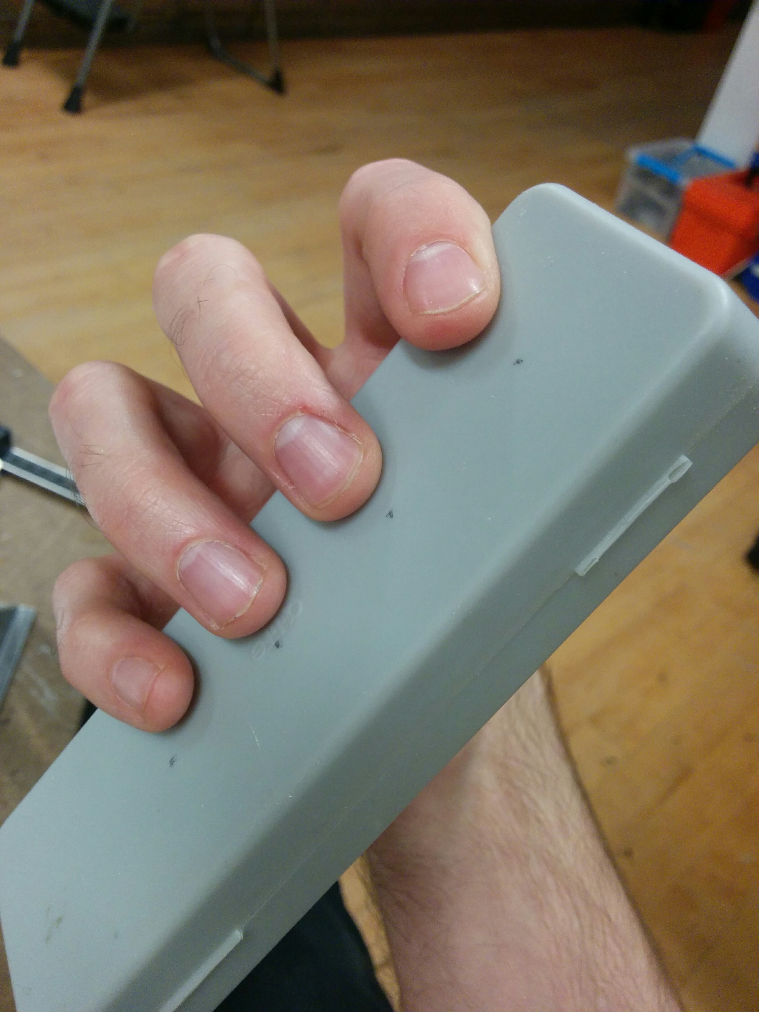
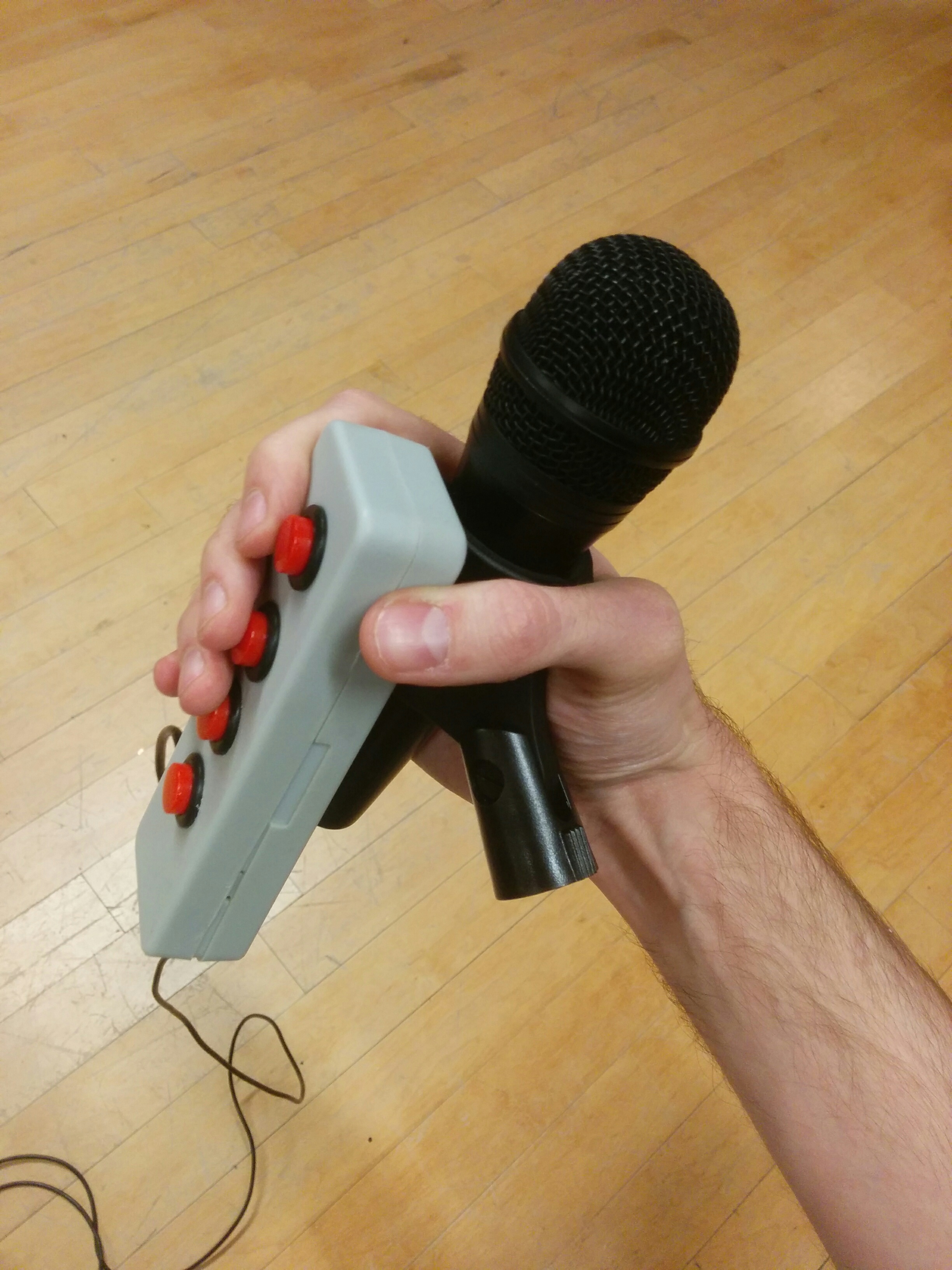
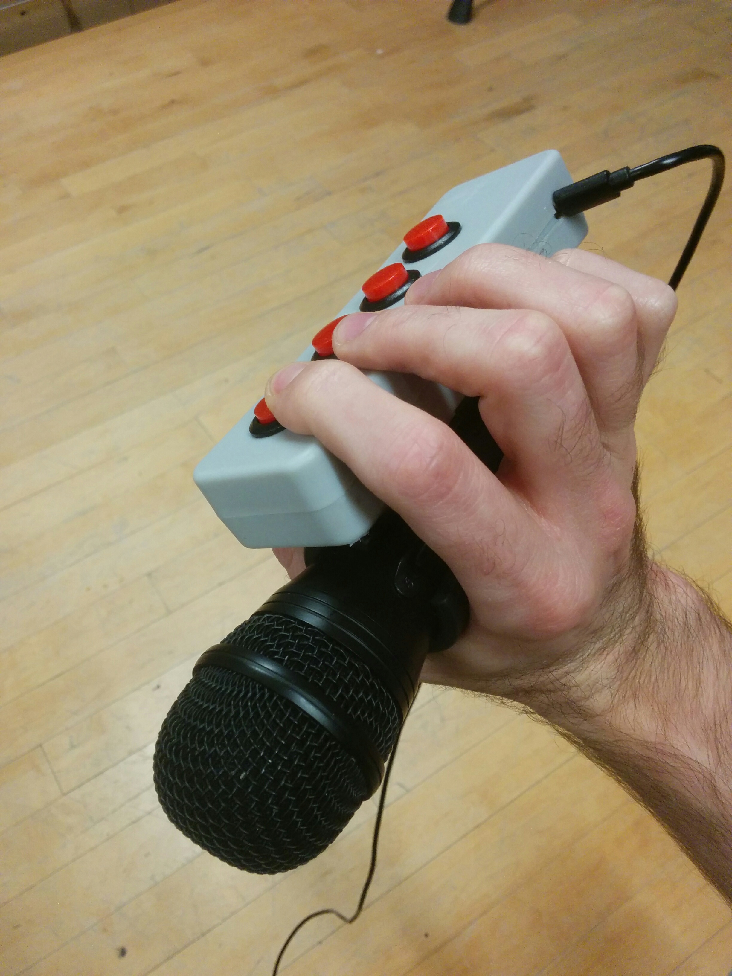
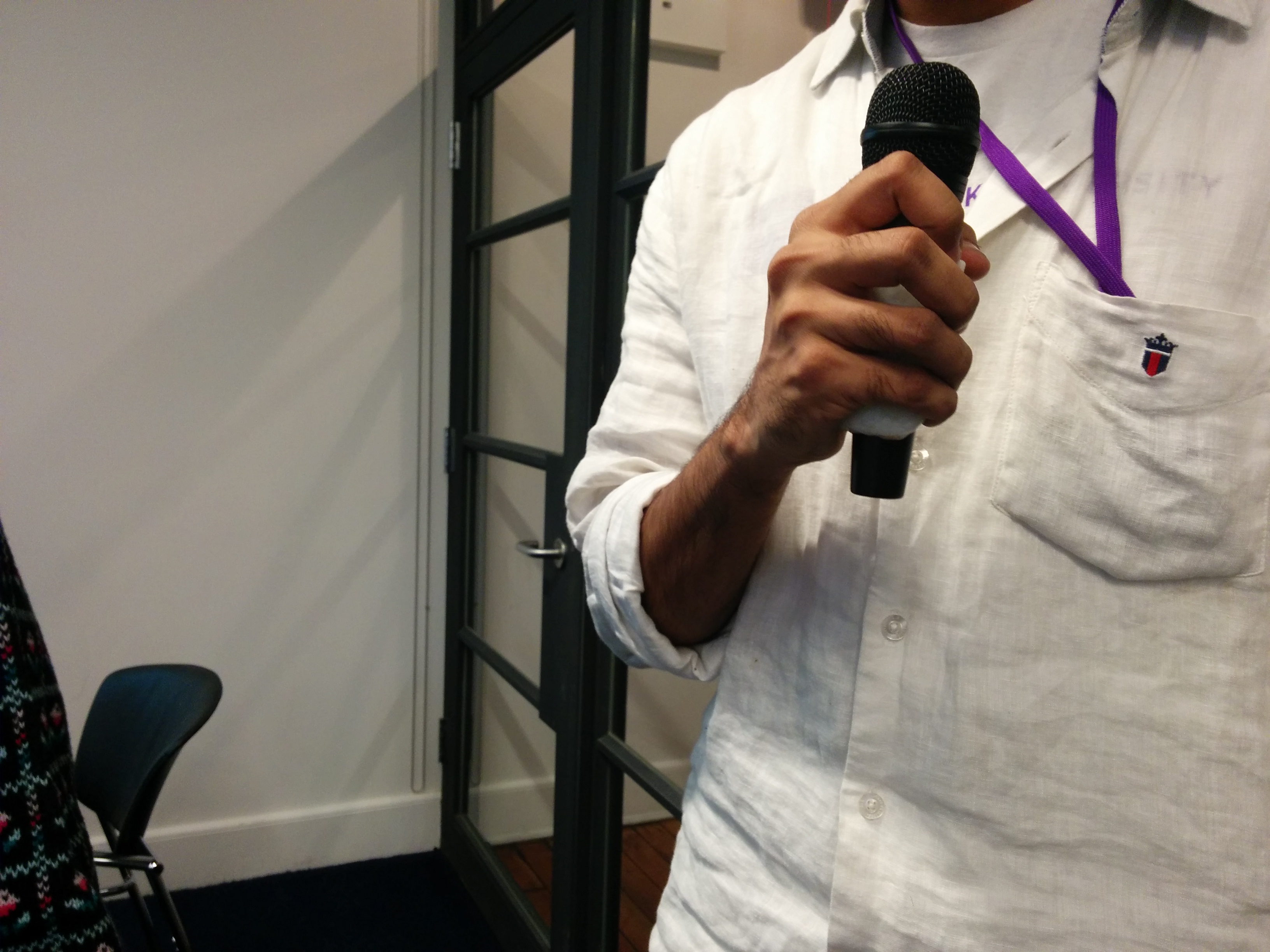
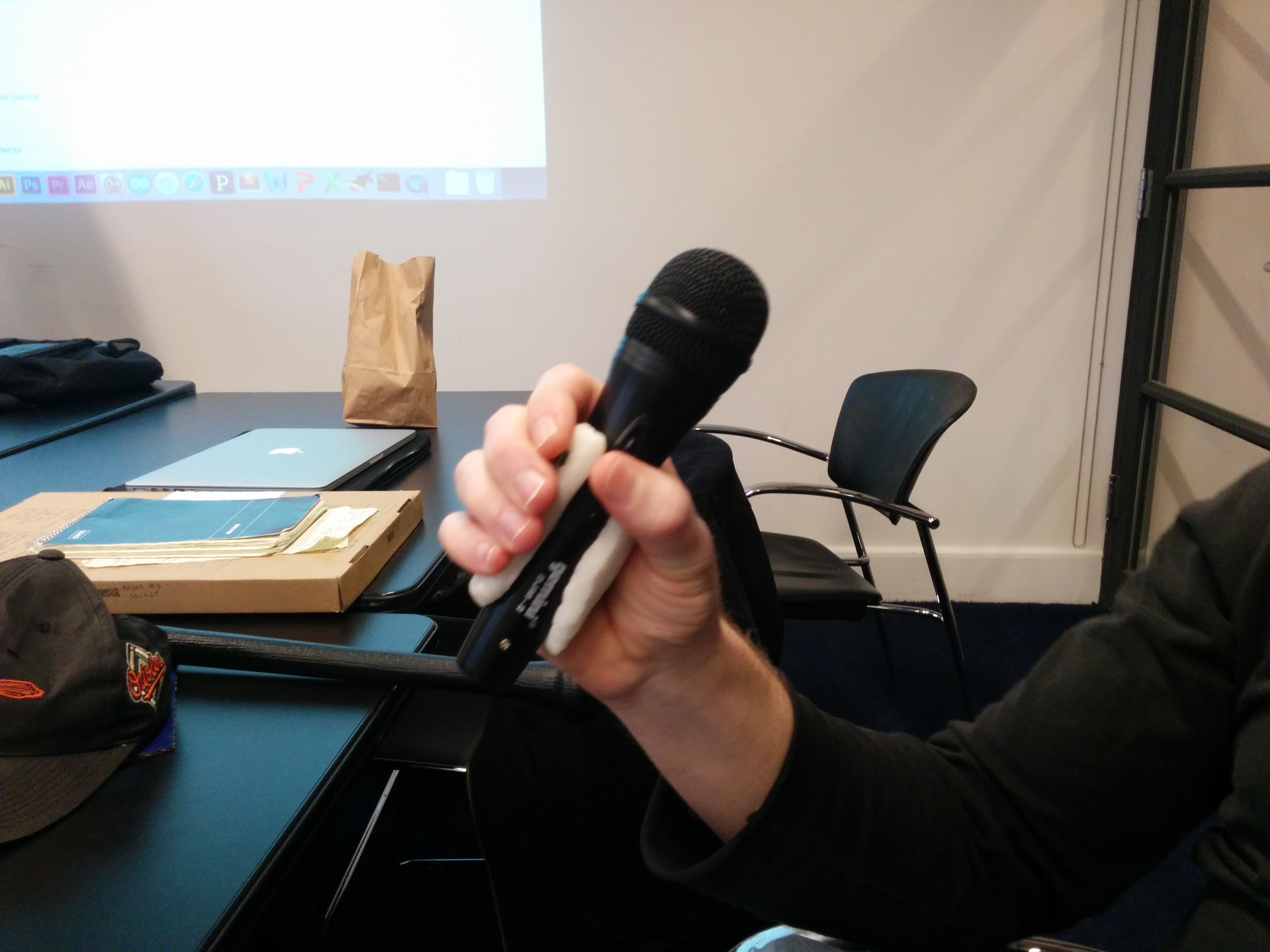
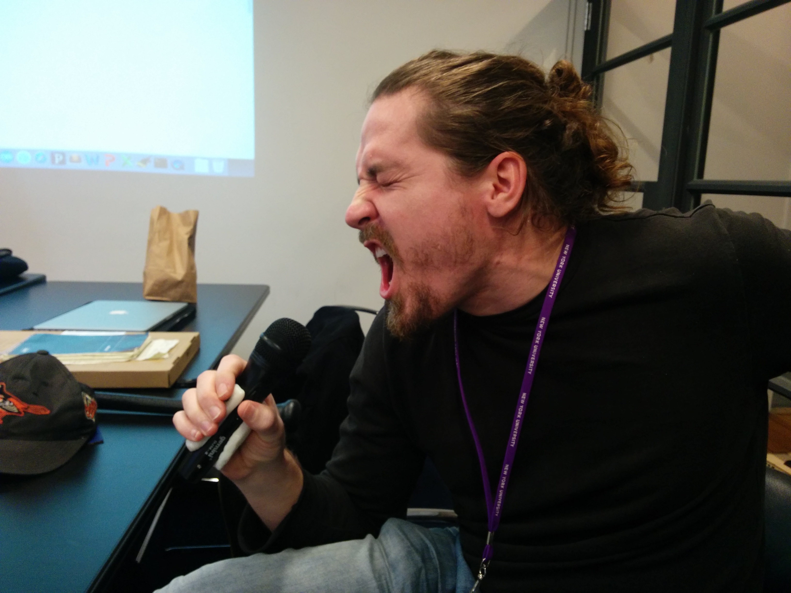
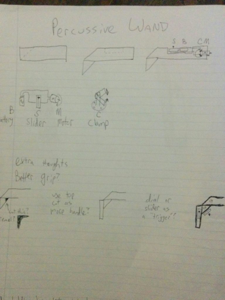
Then in class we did some play testing. I was very curious as to how people would naturally grip the prototype without any prompting. This was very useful to me to think about input placement and functionality. I could go on and on about this, but I think I will leave the elaboration for a different post. For now, let’s look at the grips:
It was interesting not just to hear what people thought would work well, but to simply see how they held and interacted with the prototype without prompting. This was a great help in planning out button sizing and placement.
I had come to a crossroads, however. Seeing people interact with the piece further re-iterated that I should further focus on an activity and a user. I am confident that I will continue to work on this in the future, so I’m not too worried about making a “wrong” choice. With that in mind, it made sense to stick with my first instinct; a device specifically for musical interaction.
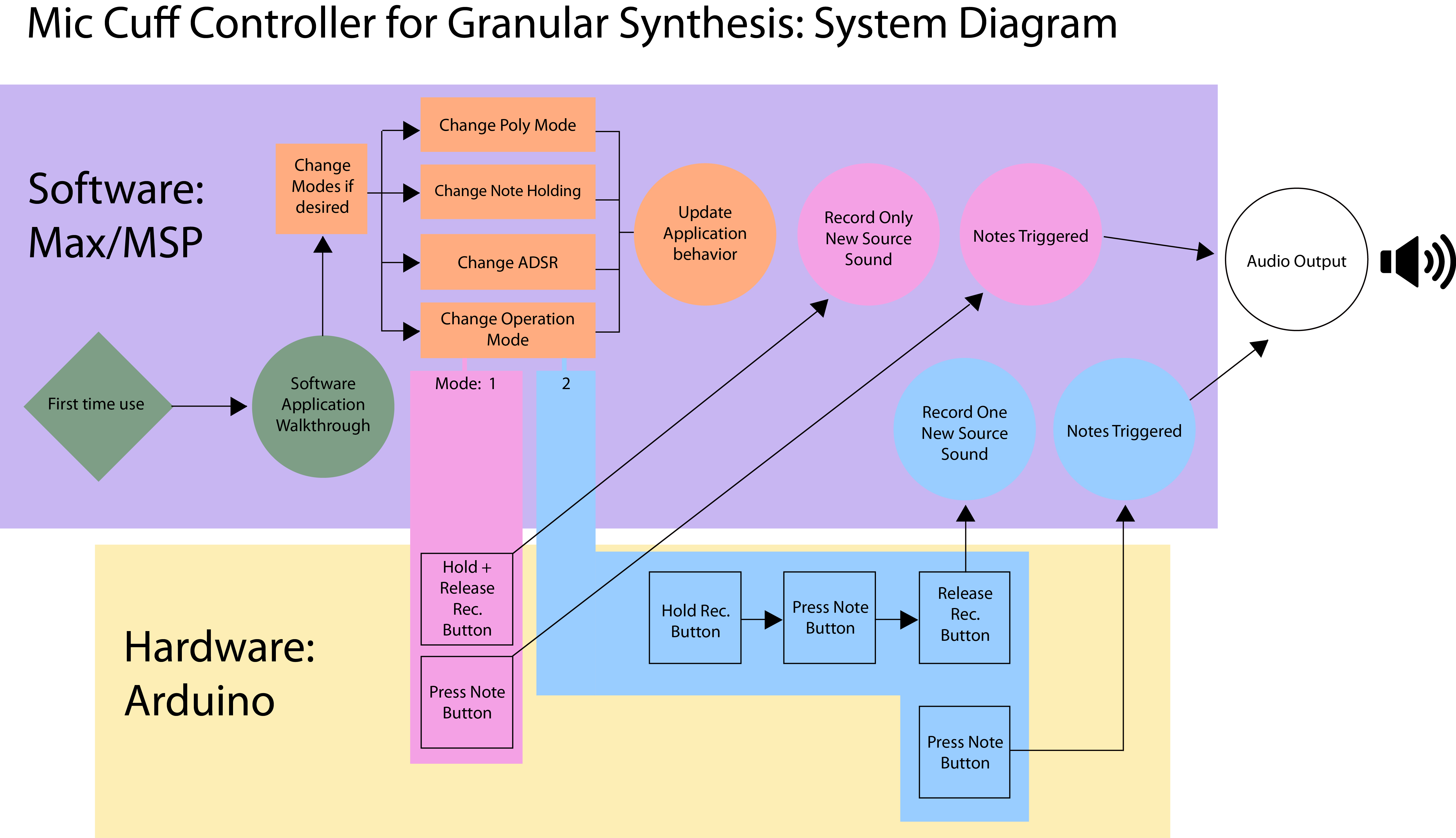
With that in mind, here is my first system diagram:
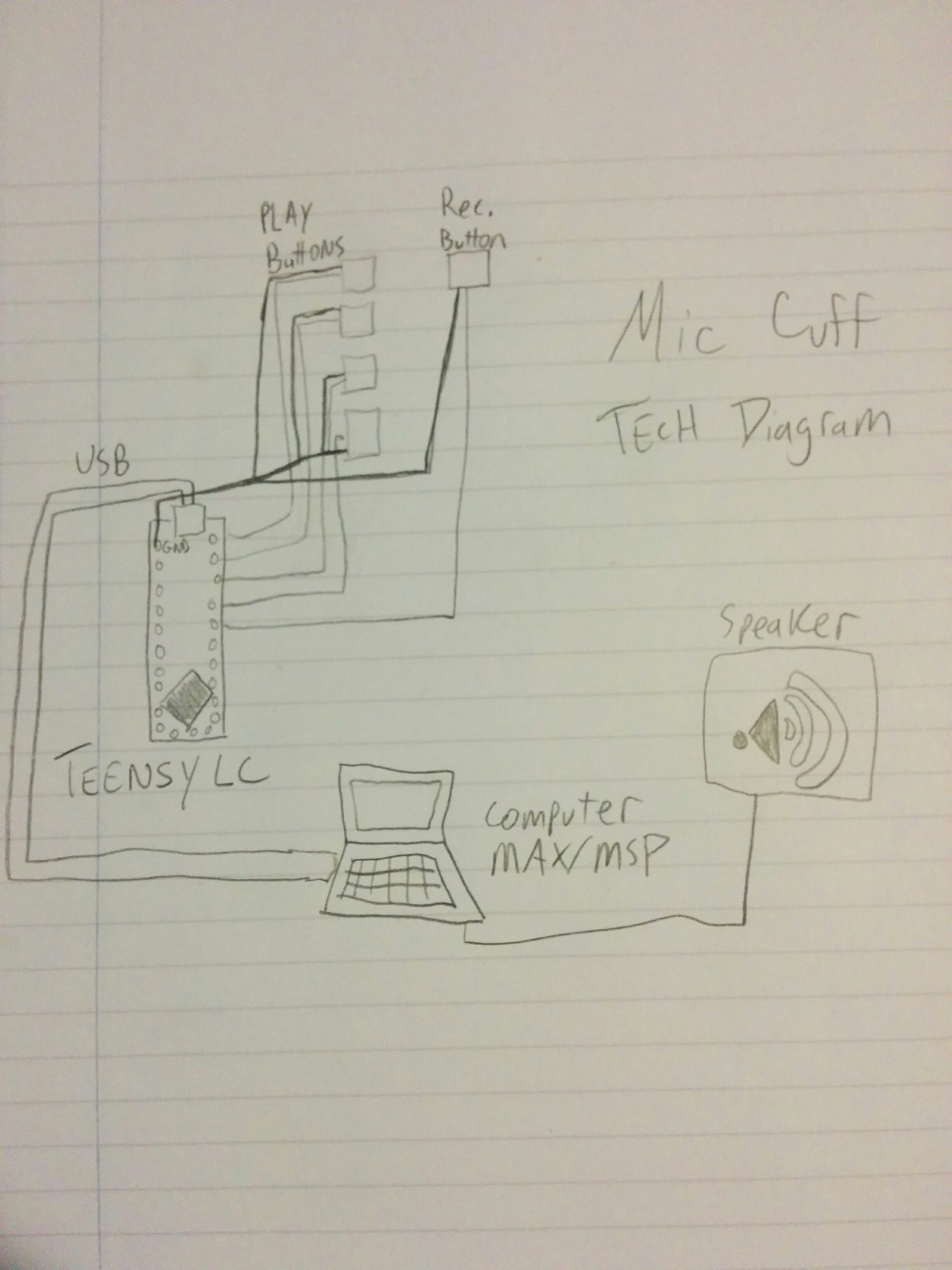
Technical diagram:
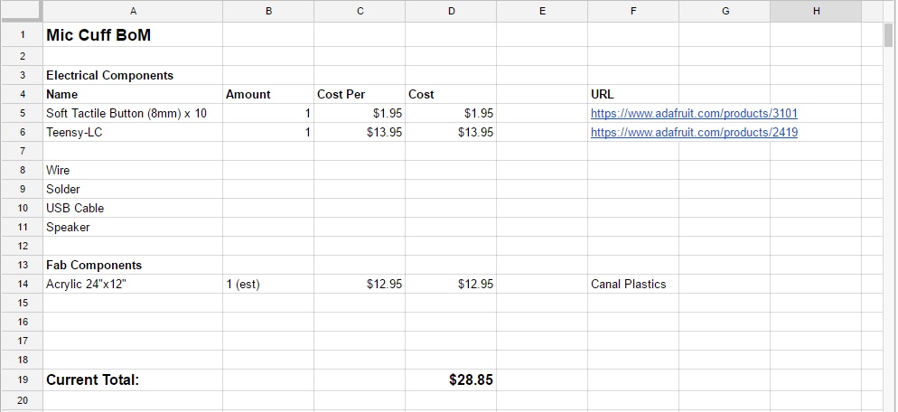
And bill of materials:
I’m going to be using a Teensy LC for it’s size, cost, and ready to rock MIDI implementation (that I’ve used before on the Teensy ++). For now, I am going to try to work some kind of enclosure of bent acrylic, but I am expecting to play around with a few different enclosure types before fully settling.
My parts are ordered and I will be doing some acrylic tests (and consulting) over the following week.
We’ve started coming in on the last half for IDS, and have been asked to start developing our ideas for final projects. While we have been studying Max MSP as our interface, we are not required to use it. However, I’ve been having a great time with it so far and I think it could be of great use for my particular interface.
For Intro to Physical Computation, I’ve been developing an idea for a physical prototype. It is a cuff that fits around any standard sized microphone that would also have input buttons on it. These buttons would be used as user input, so that a performer would not only be able to communicate with the microphone but also interact with software while performing.
I’ve had a decent amount of discussion with Benedetta and my classmates about more specifically identifying an end user, and hence activity. My claims of, “Anyone using a hand held microphone with a computer!” didn’t seem to make the cut. As I had originally conceived of this as a musical performance device before expanding my horizons, I decided it was best to bring back the concept to it’s original roots and stick with that for now.
However, for IDS, I would still like to explore the idea of giving users greater control over how their software and hardware works. Trying to balance customization, ease of use, and meaningful options for interaction seems like a healthy but worthwhile challenge.
For Physical Computing, I will try to focus on one use case for that project. But for IDS, I would like to iterate on the functionality and create multiple use cases for my physical prototype. In order to avoid casting too wide of a net, I will start by focusing on musical applications. The end goal would be to create multiple modes of interaction that are easily changed from mode to mode, customizable, and have all of this interaction clearly understood and easily used by a non-technical end user.
I will need to clear my idea with both professors in order to properly section this project into pieces that satisfy the requirements for both classes. It would also be good to clarify with Luke the specifics for IDS: How many different modes would be appropriate for this objective? How far down the “non-technical end user” rabbit hole should I go? Which existing software interfaces should I be aware of when trying to implement this idea?
Looking forward to seeing this idea come to fruition.
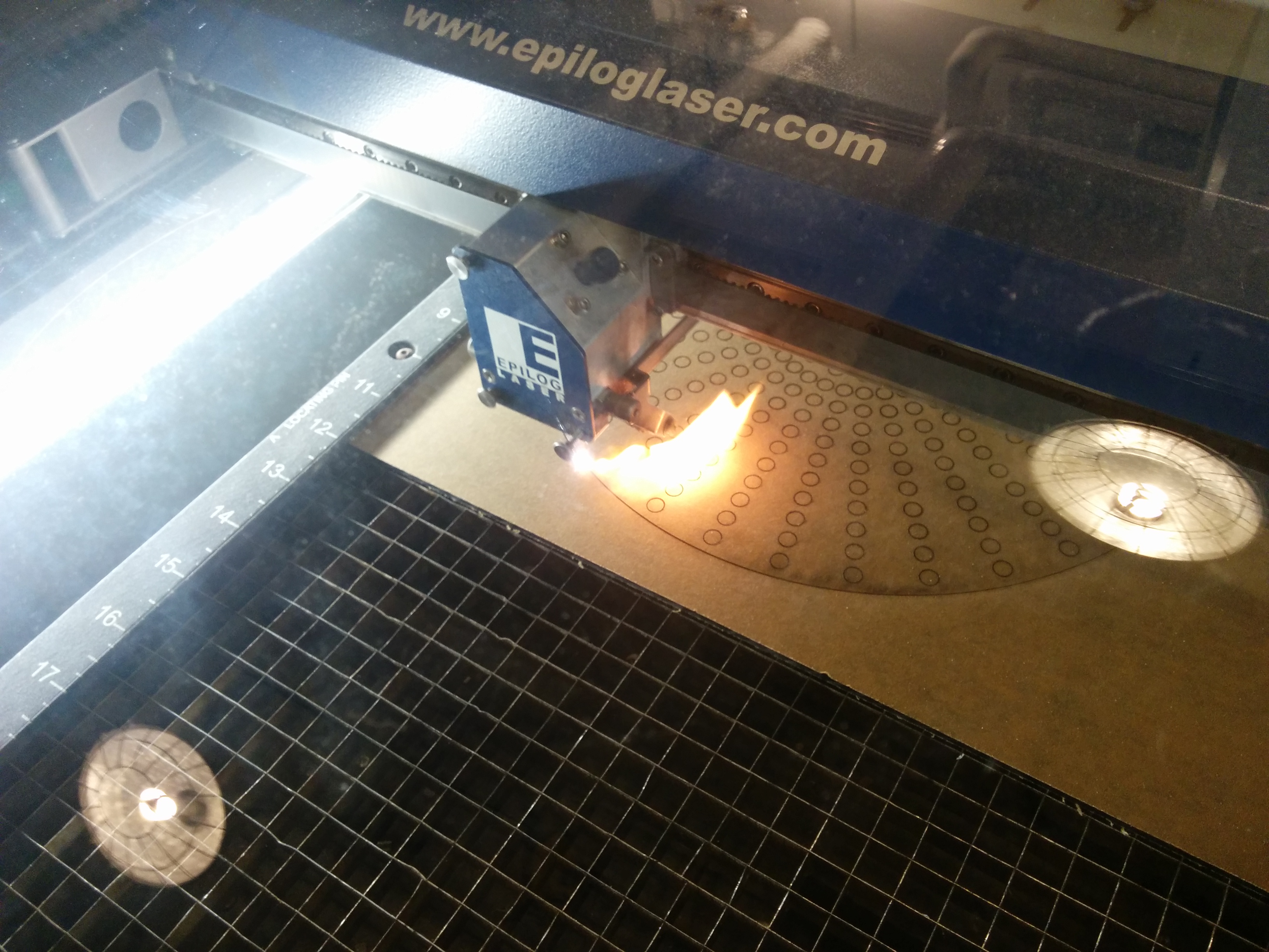
“Don’t fall in love with the laser! DON’T fall in love with the laser!” While I will never forget Ben’s words, I will say that at the very least I had a great weekend with the laser and I will be calling it back.
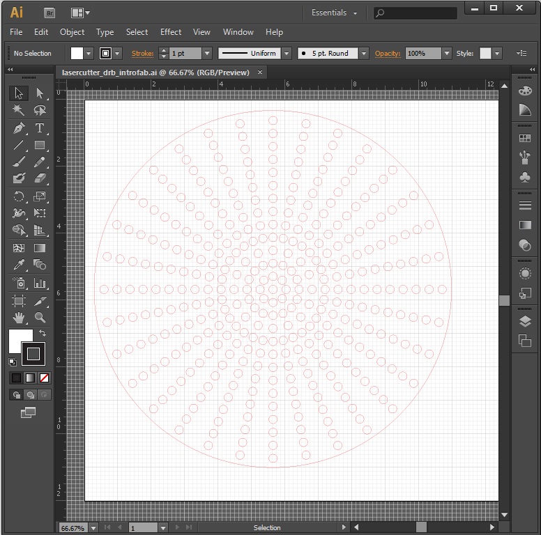
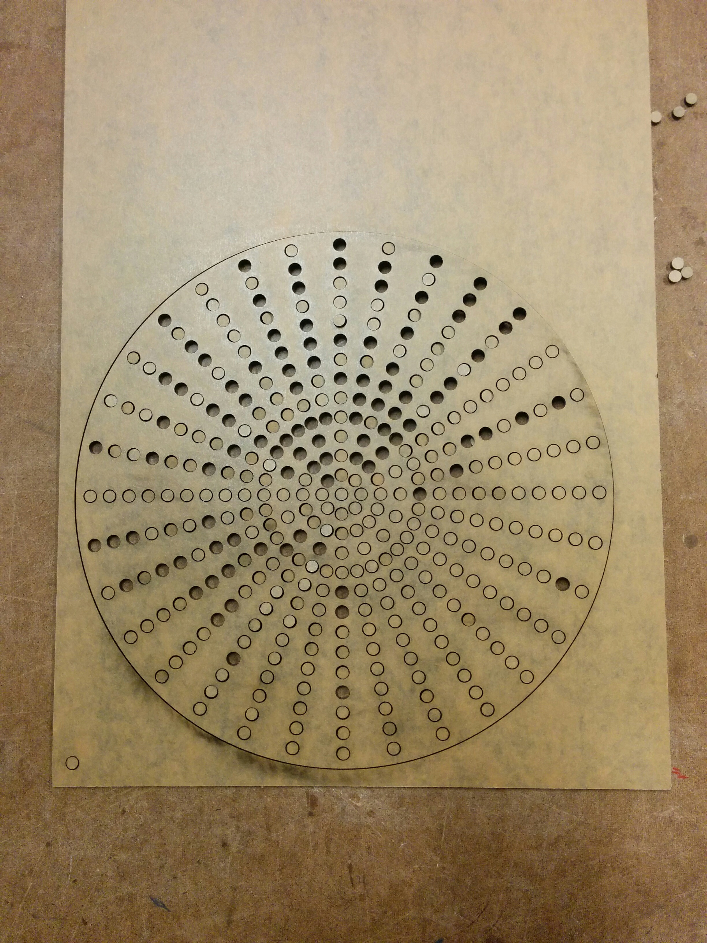
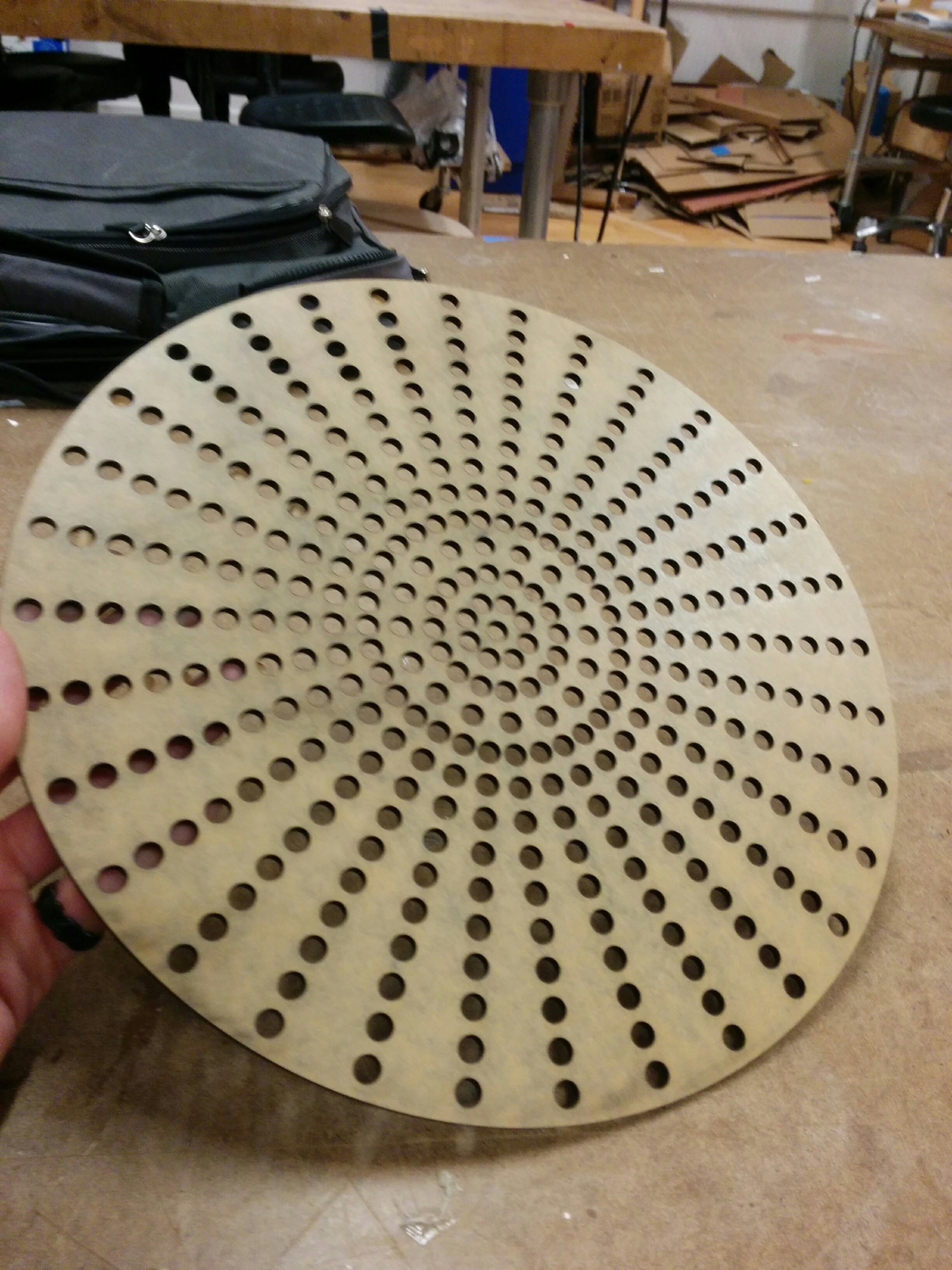
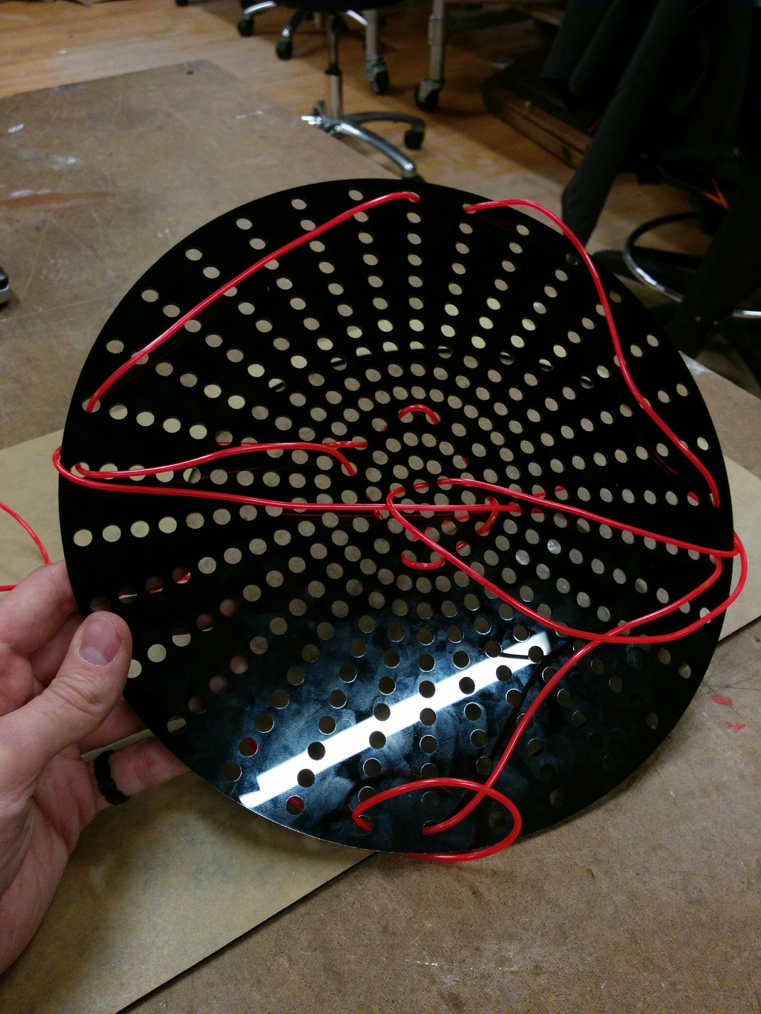
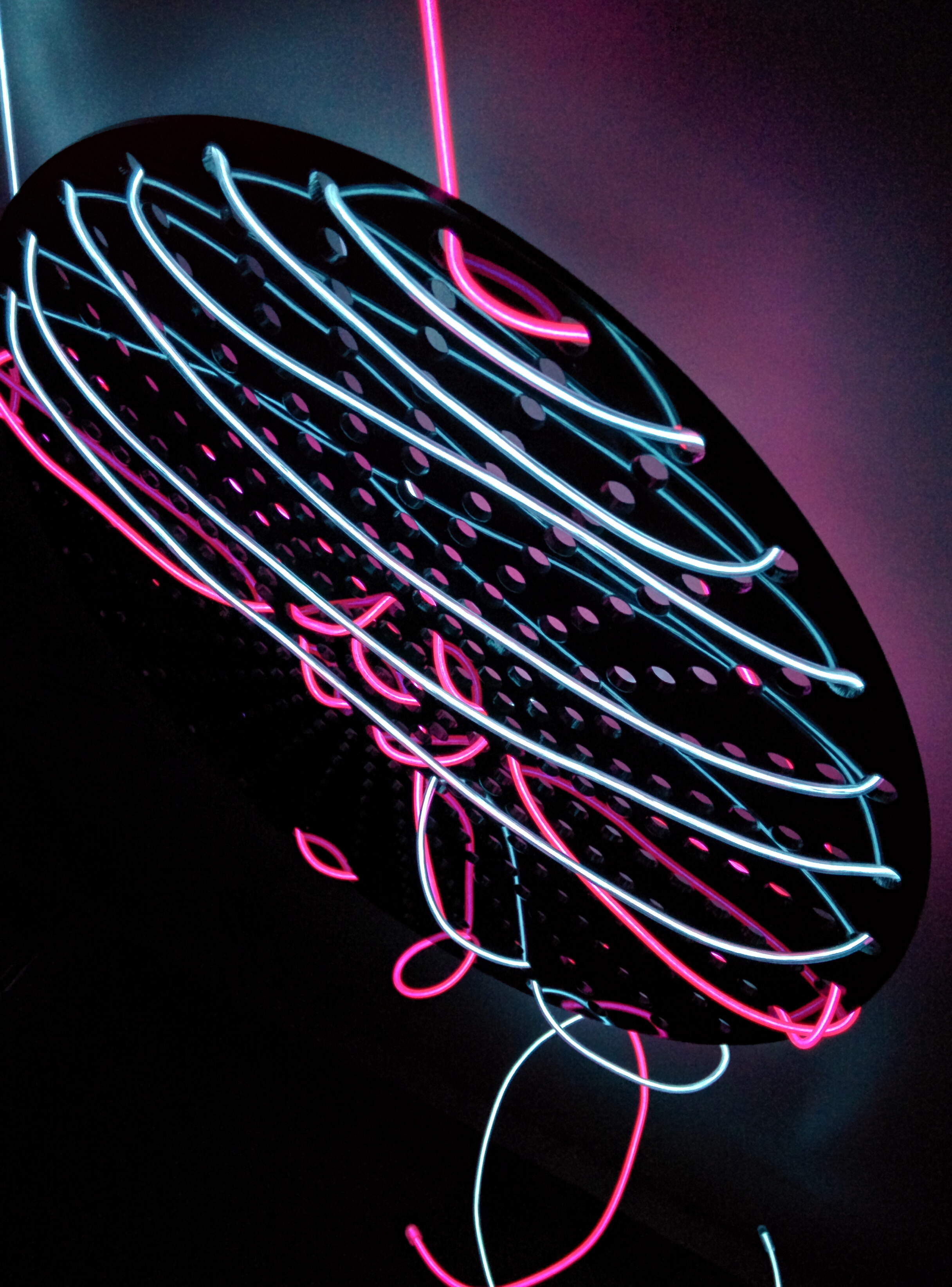
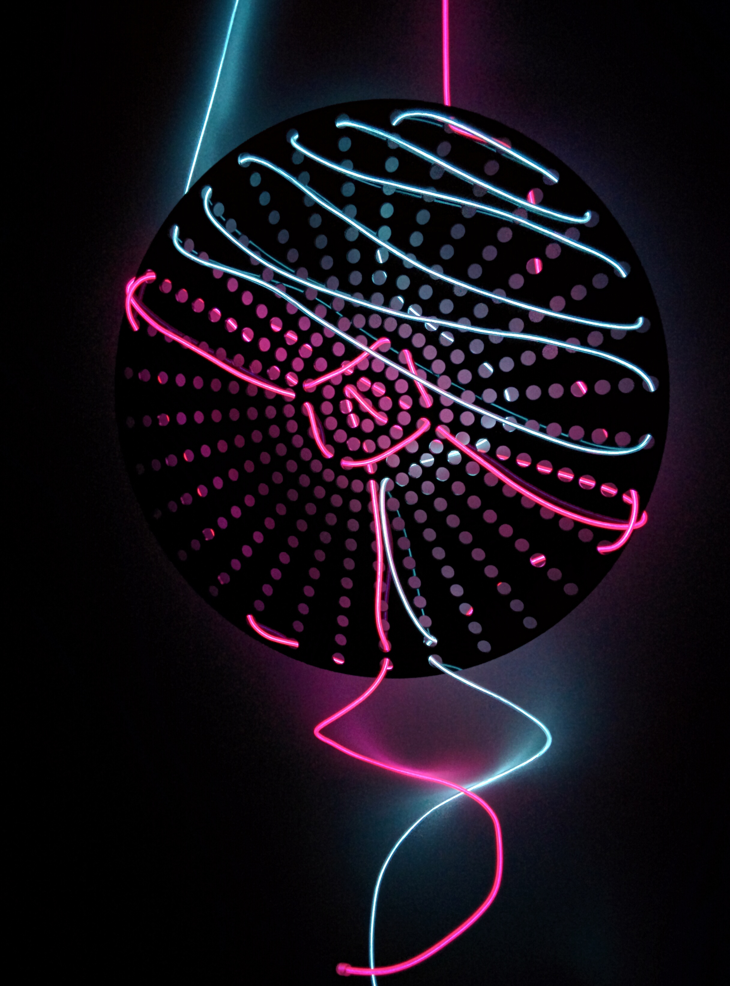
Having never used acrylic before, I was curious about making something that could accentuate the shiny, slick qualities of it. I had some EL wire around that I hadn’t gotten to use yet, and came up with a lighting idea. An acrylic cut shape with multiple holes in it that I could weave the EL wire in and out of. The wire seemed sturdy enough to hold itself and light amounts of weight, so I got excited enough about the idea to see how it would actually work.
I was really happy with my trip to Canal Plastics. They were a great help, there were a bunch of 24″x12″ precut sheets of laserable acrylic that fit our bed dimensions perfectly, and they offer student discounts of 10%.
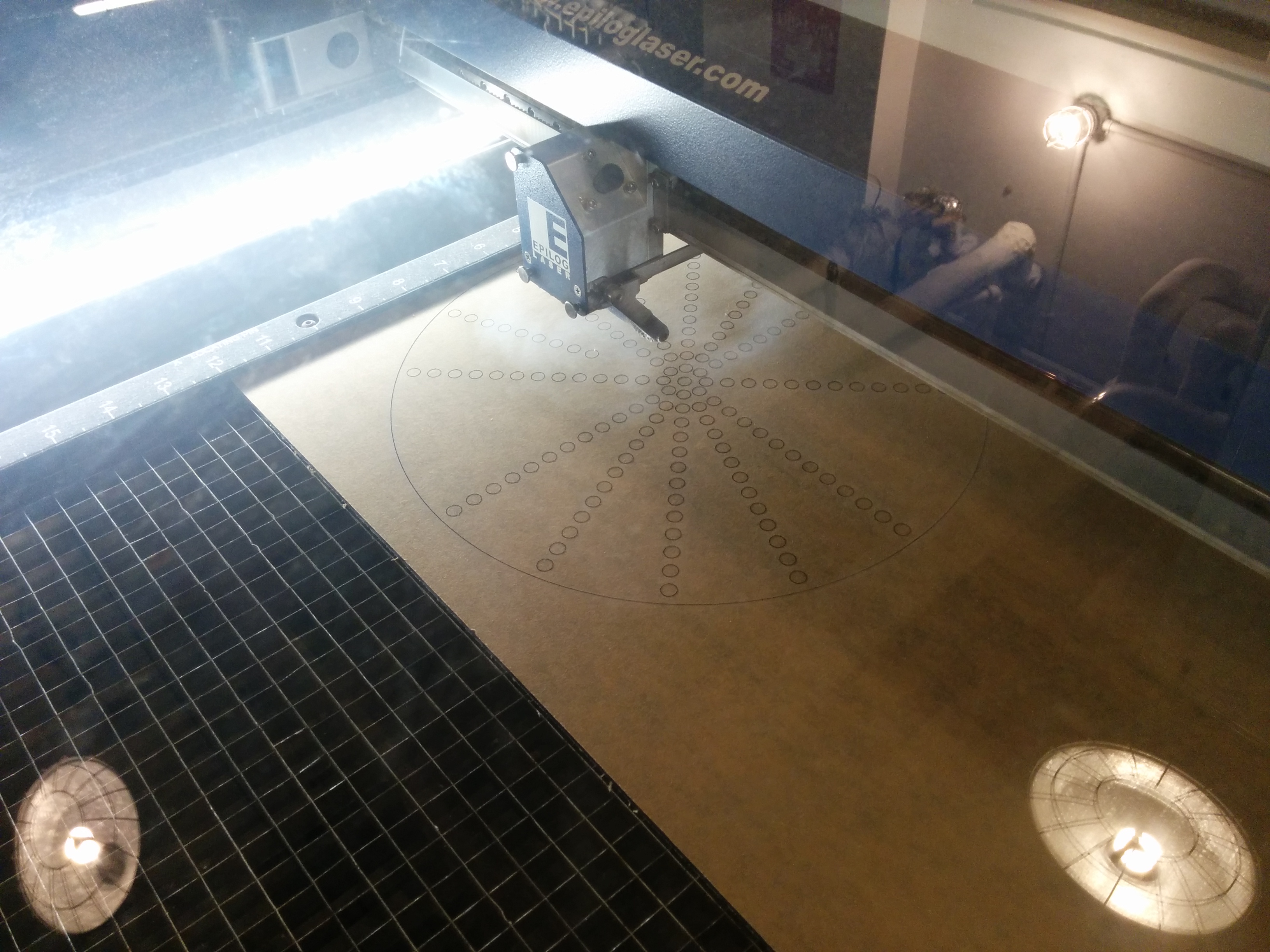
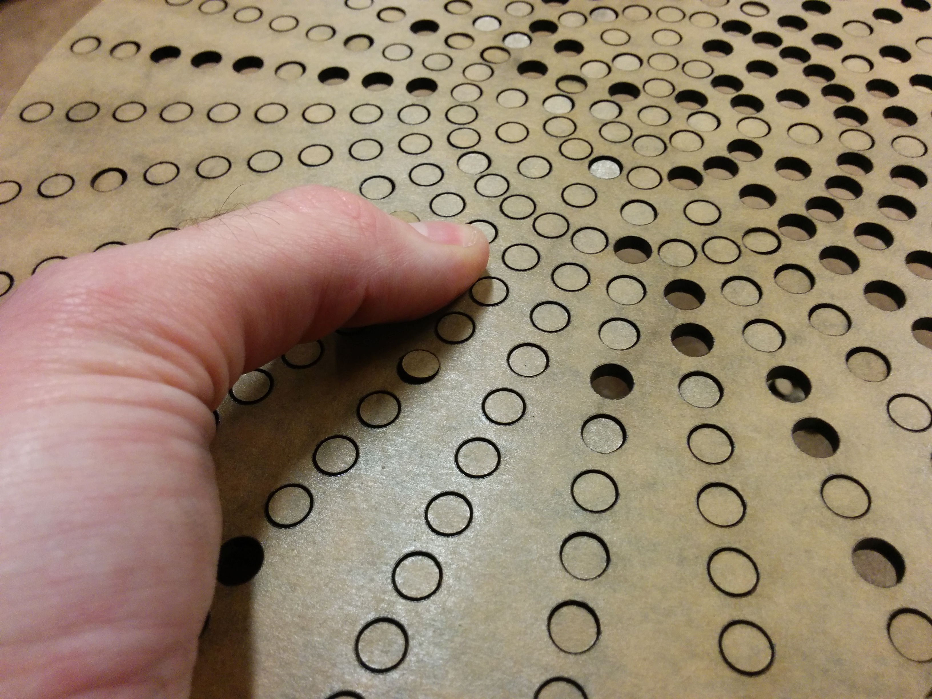
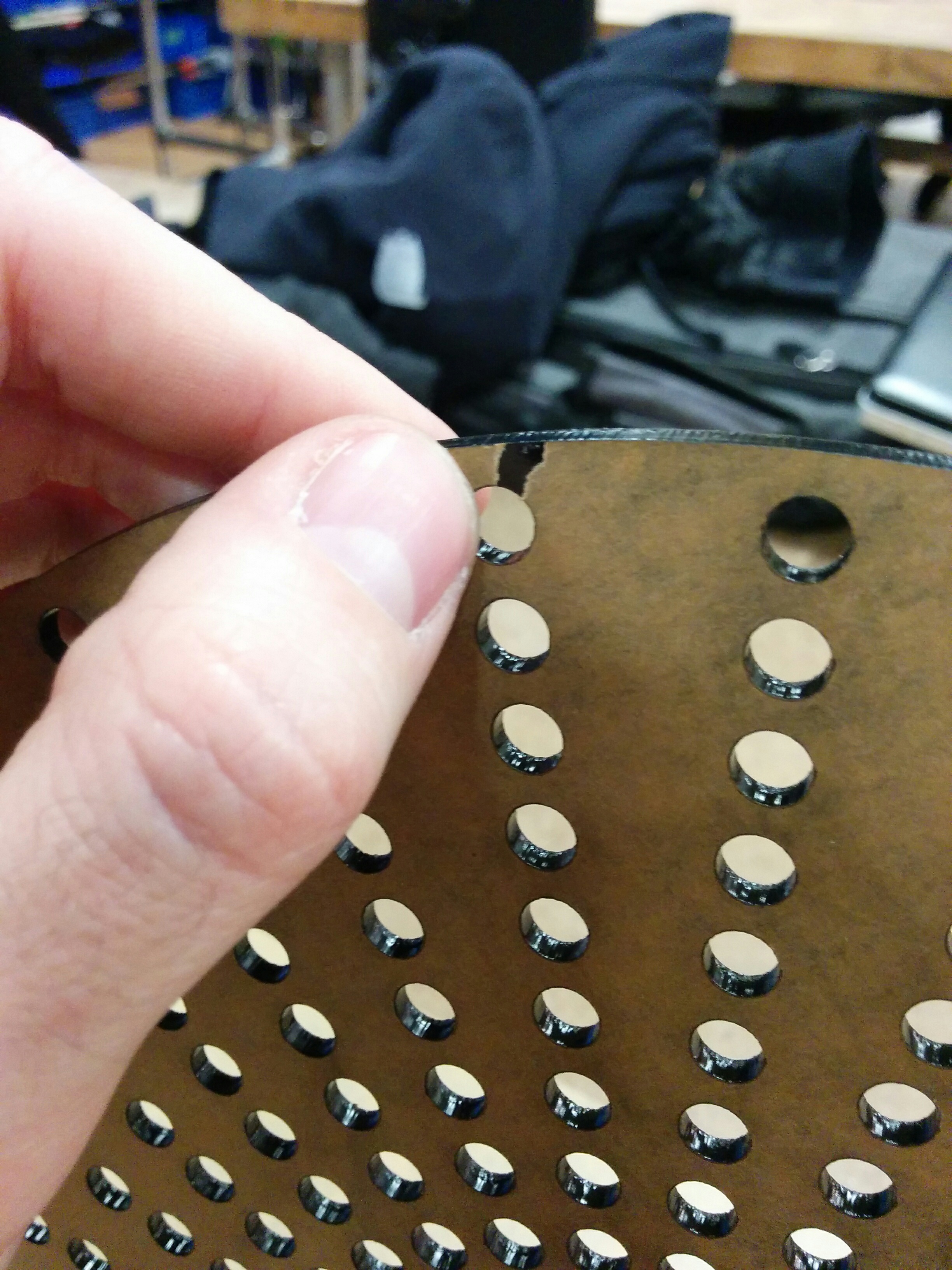
I was advised by people in the shop to keep the paper on the acrylic while laser cutting, and given some friendly advice about speed, power, and frequency. I started cutting at 50/100/100.
I ran it twice just to be safe.
But it wasn’t budging, and the tape trick of trying to pick up cut pieces was not working at all. After further discussion, I dropped the speed to 30.
A few flareups on the surface convinced me thoroughly why the fan needs to be on. However, after two extra times on 30/100/100… still not budging…
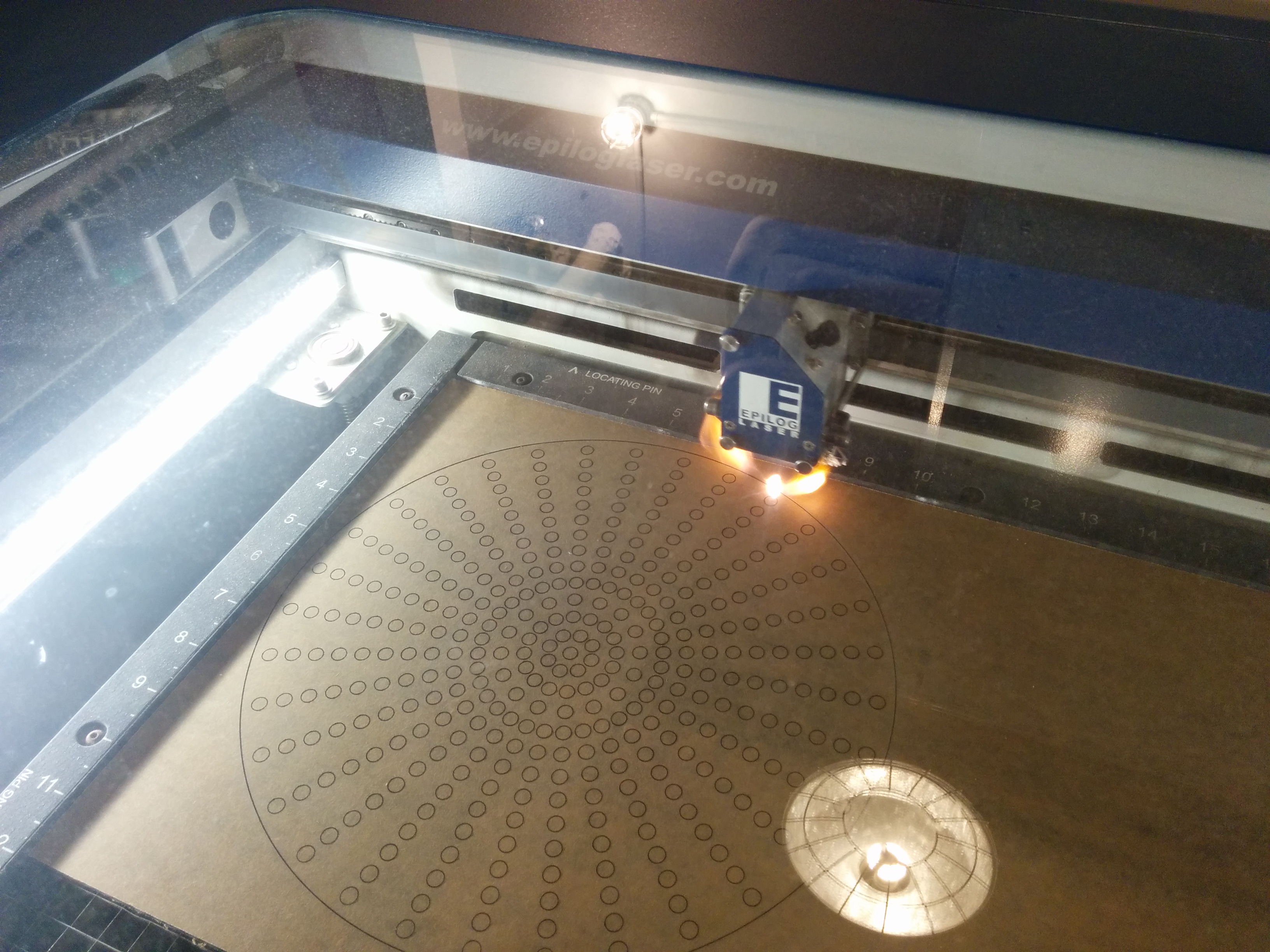
Take advice, but cautiously. And double check everything. After 4 laser sessions, I went to the source and checked the cutting guide on the ITP website. Suggested speed? 15. Change the settings and here we go.
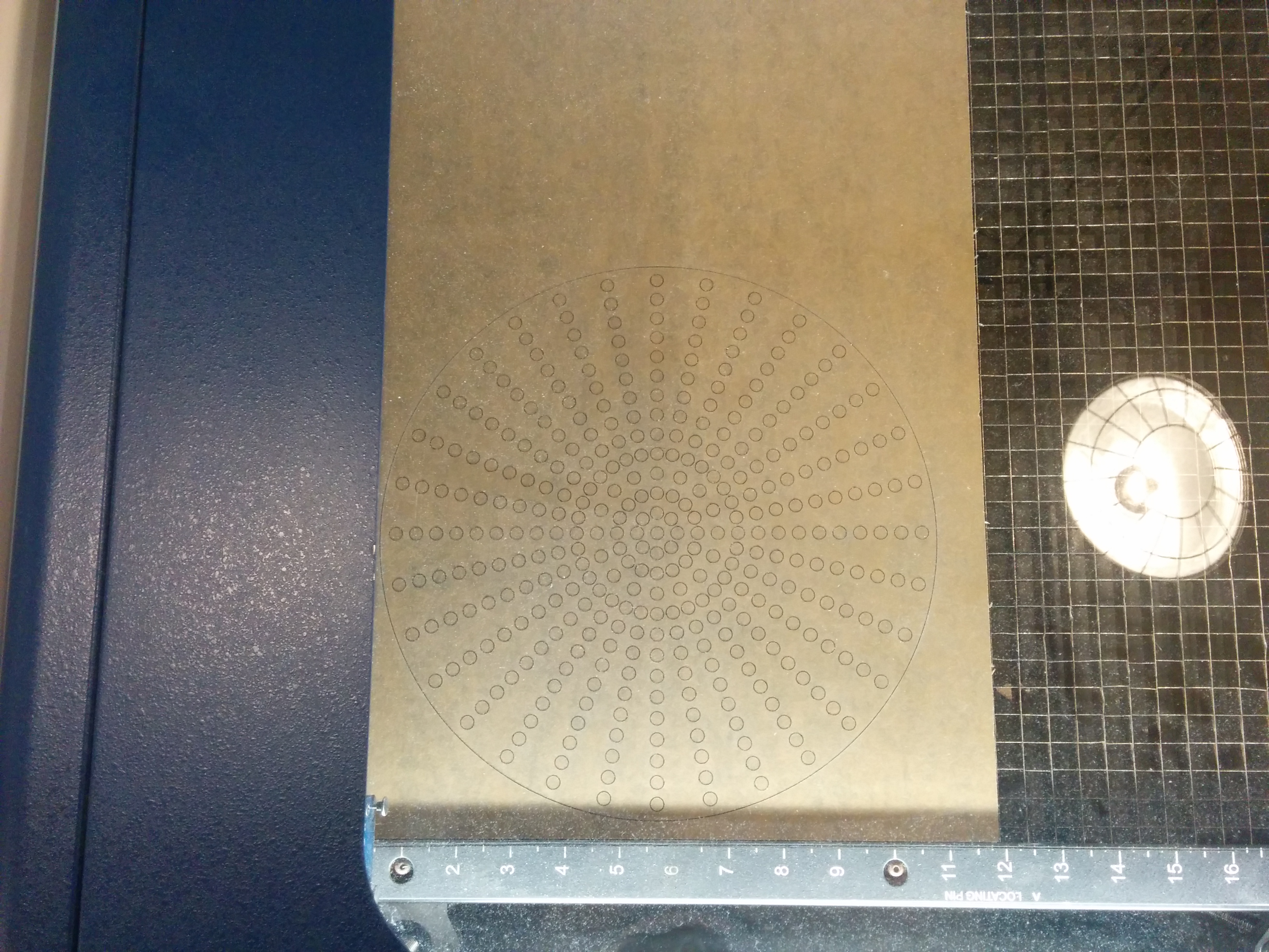
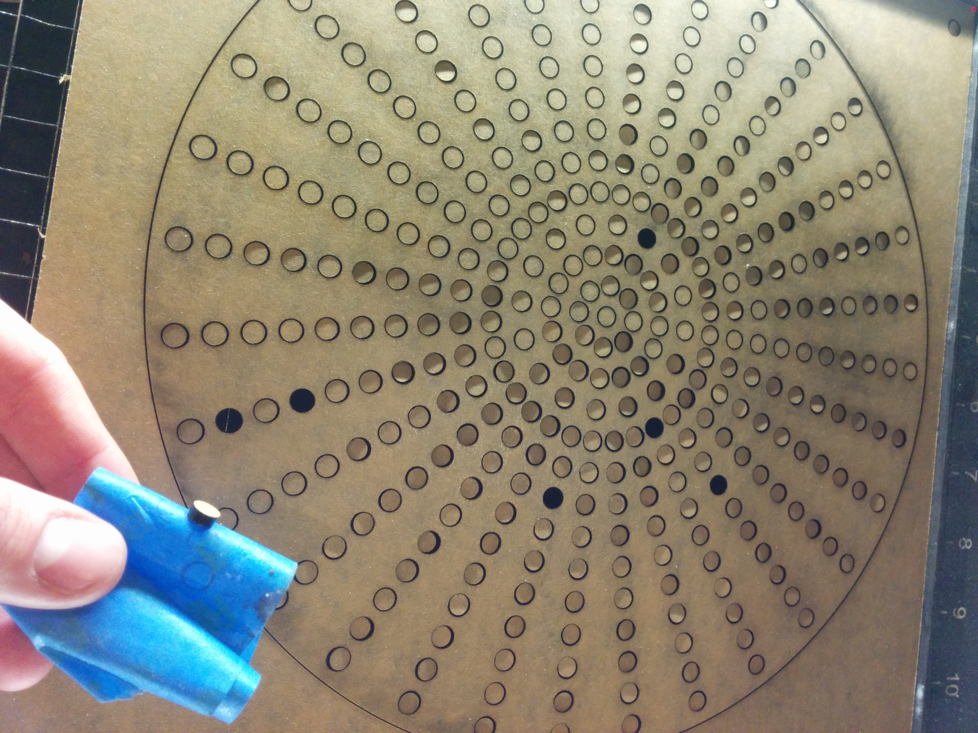
Woo! Really glad for that fan now. But it was working. The pieces were starting to fall on their own.
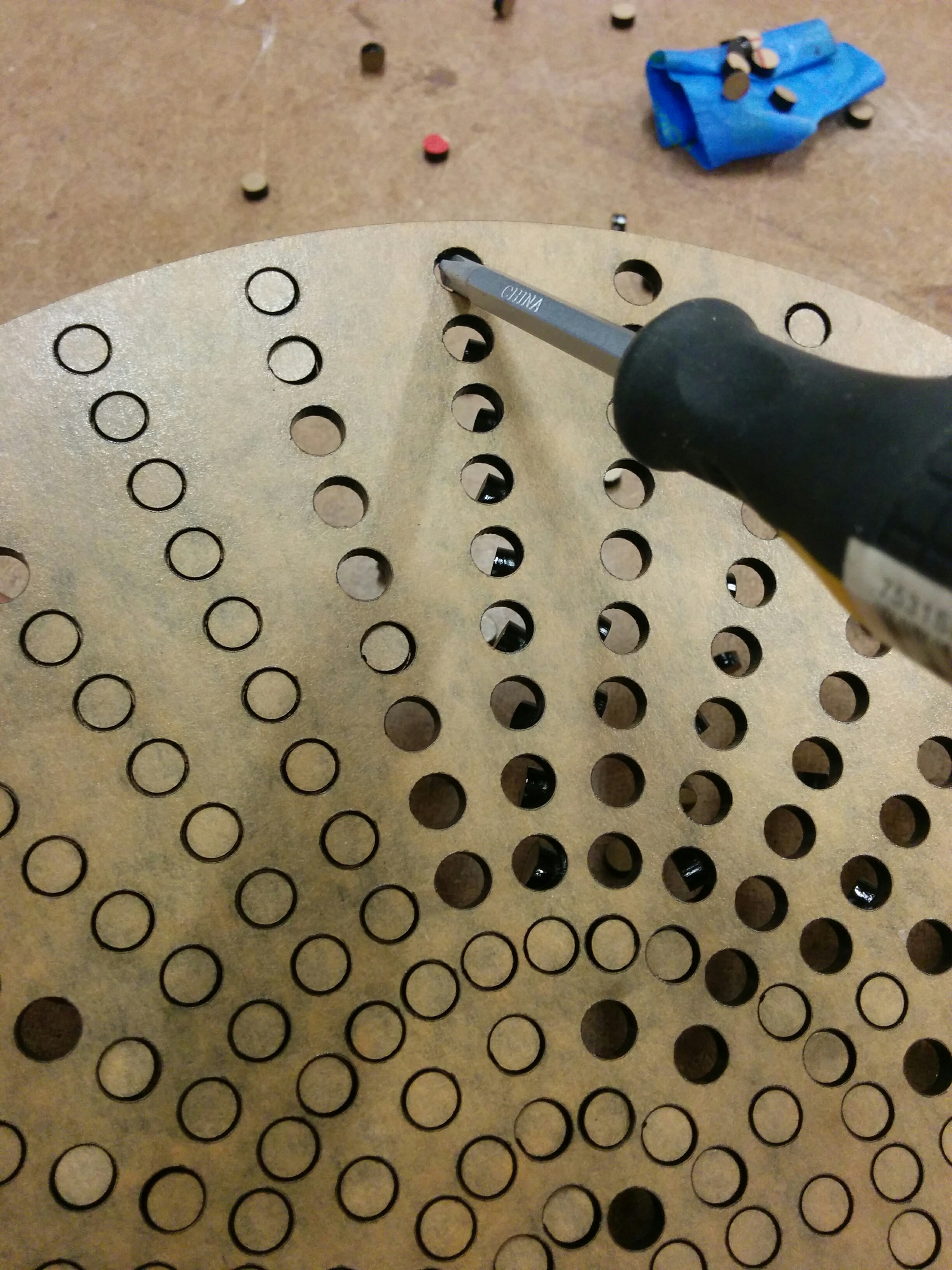
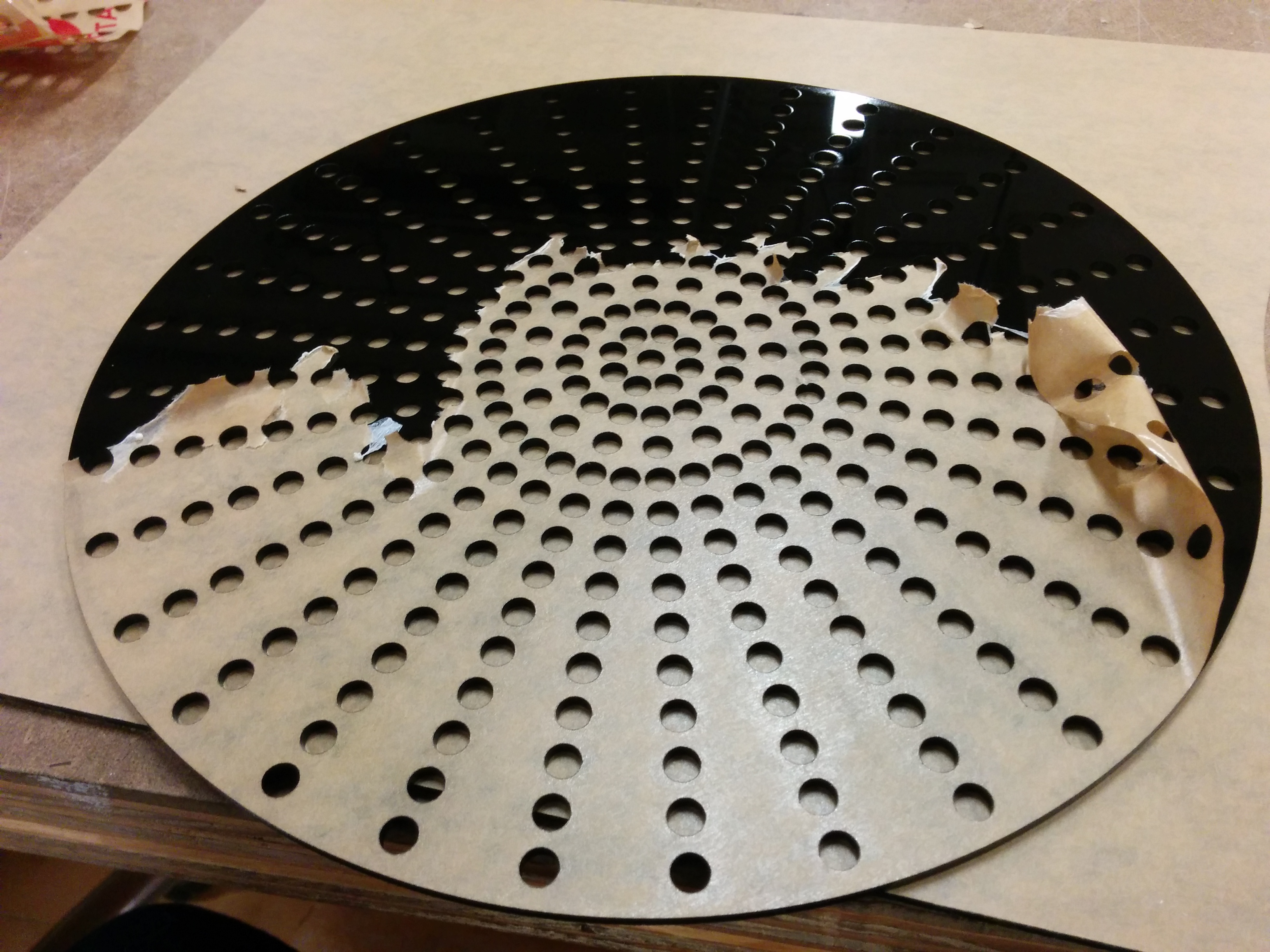
And the tape trick was working like a charm. I moved everything to a table and started popping out the little pieces. Using my hands was fun, like popping bubble wrap. But towards the lower right side I needed to use a screw driver for a little extra help.
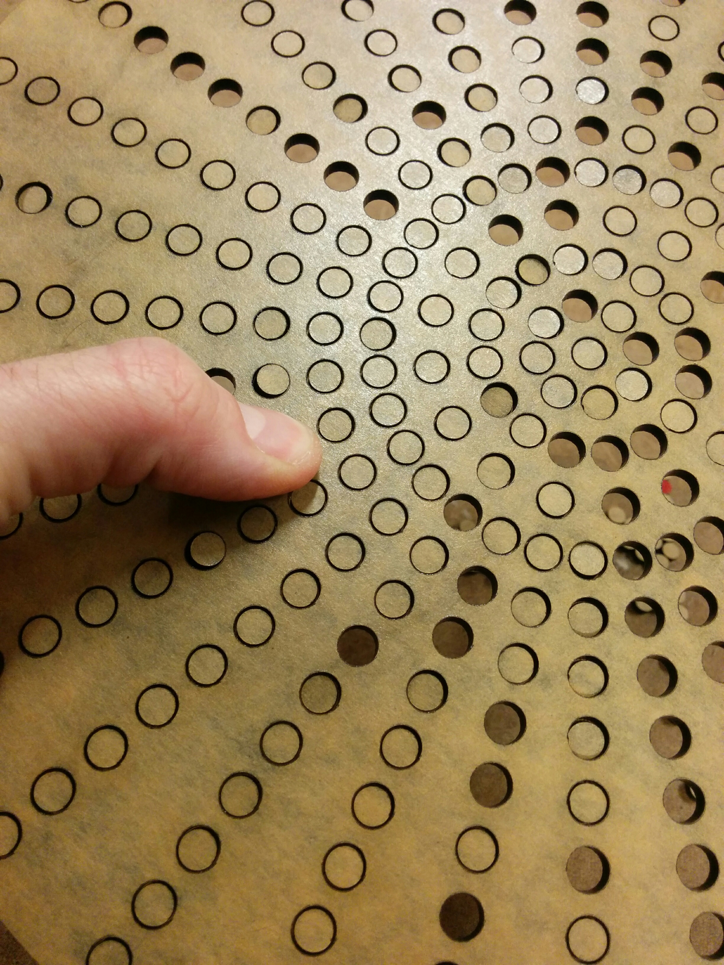
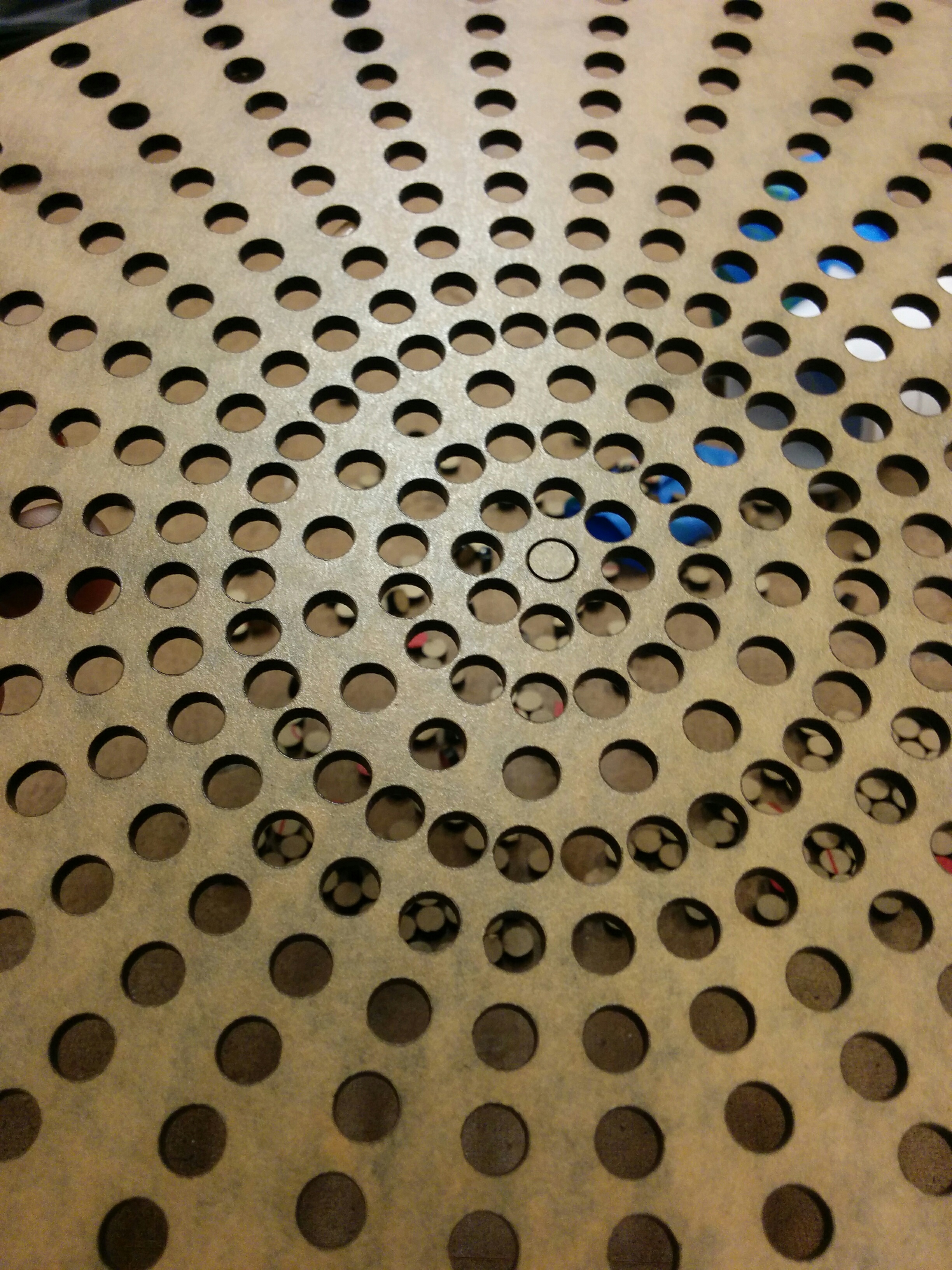
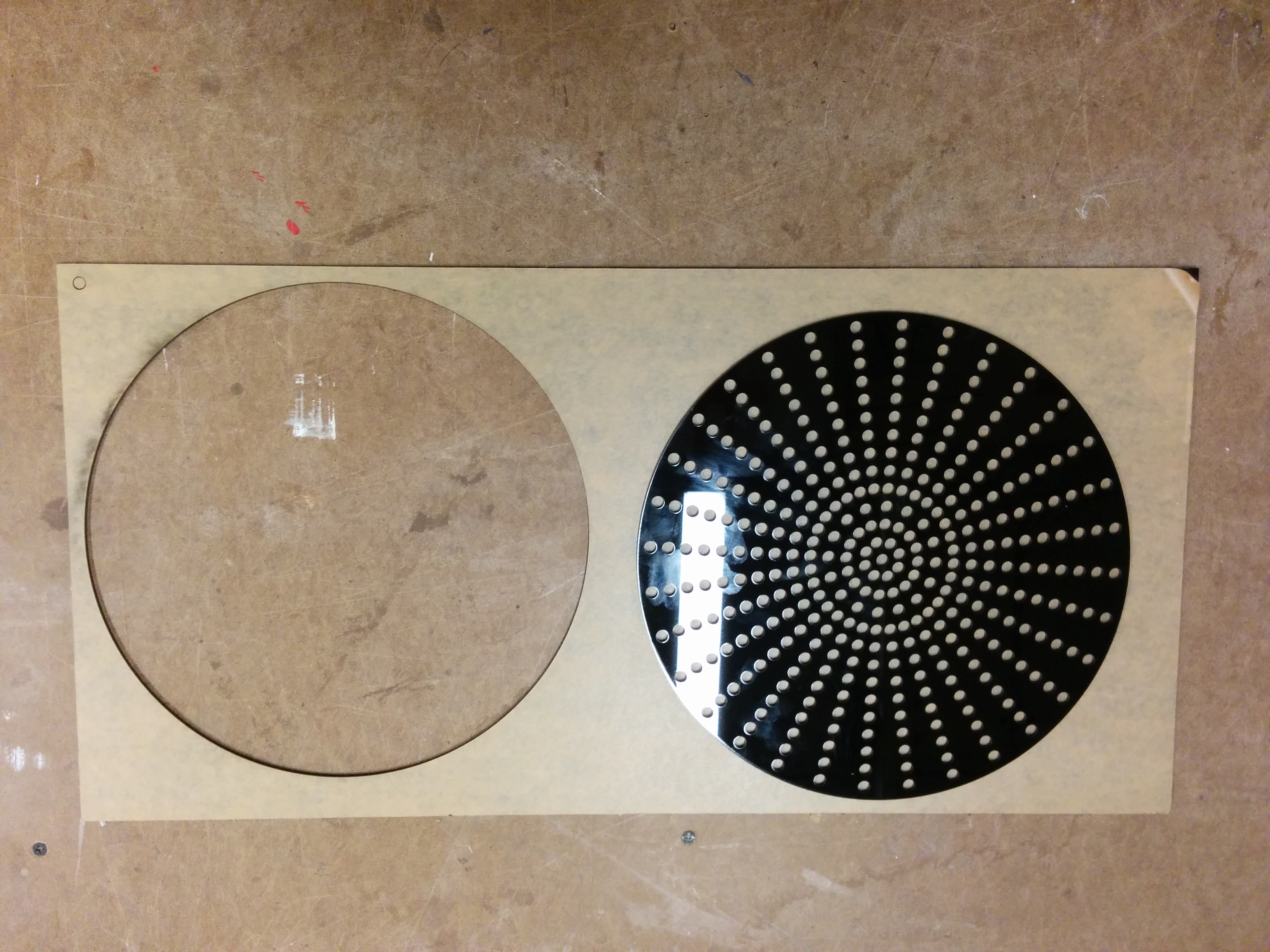
And then I started removing the tape
I think that, in the end, I am happy I kept the tape on. Being able to see the laser cuts (or lack there of) was a real help when I was having trouble. However, it was a bit finnicky cleanly taking all of it off when there were so many intricate cuts. Worth keeping in mind for future jobs.
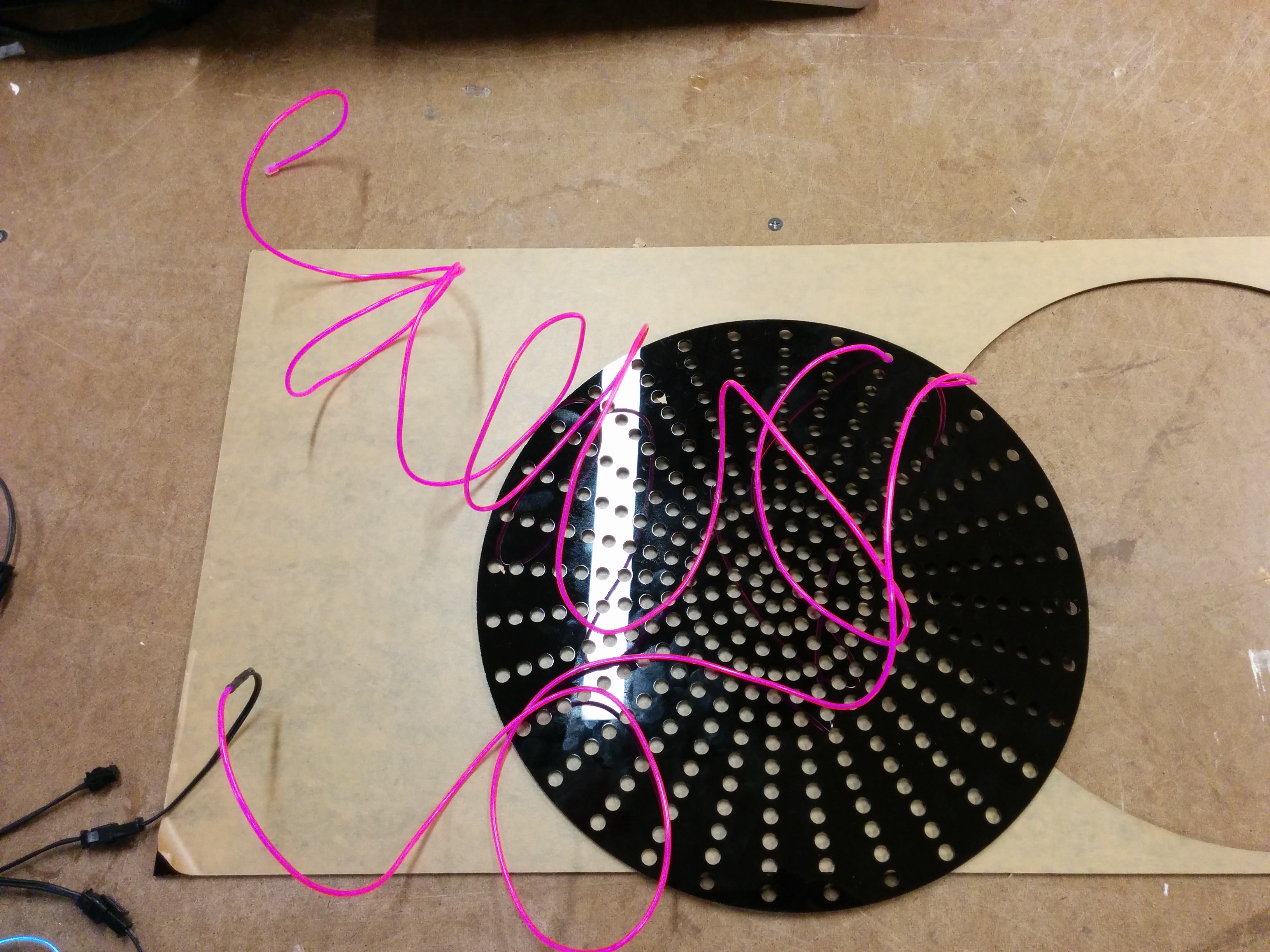
Next up was the EL wire.
I think there should be honest subtitles for classes at ITP. This should be, “Intro to Fabrication: Why did I think that one part would be easy?” Feeling like I was done, I started “just” threading the EL wire through the holes in my desired pattern. Getting to know the right amount of flex and force, trying to keep things straight, double checking my work, all while trying to be gentle with everything was more difficult than I thought it would be. Essentially, I’m trying to do a kind of EL wire cross stitching. It is possible, but just for the record, not nearly as quick as with needle, thread, and cloth.
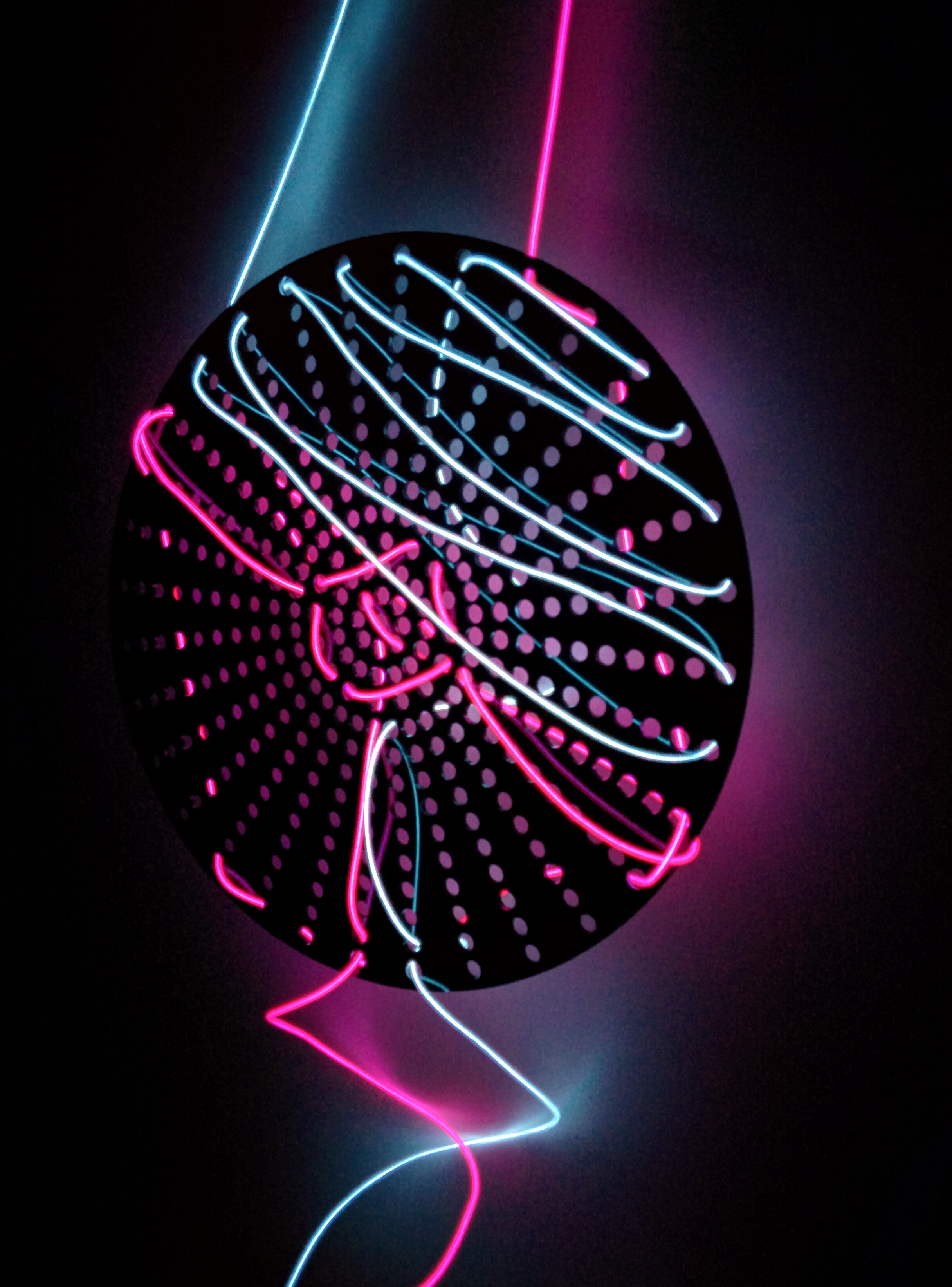
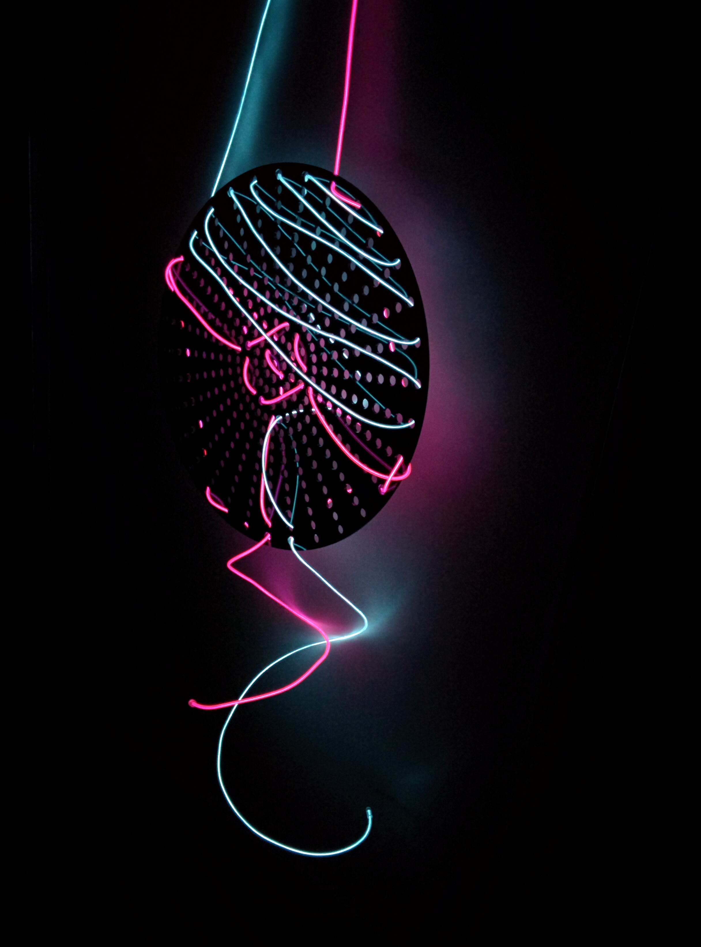
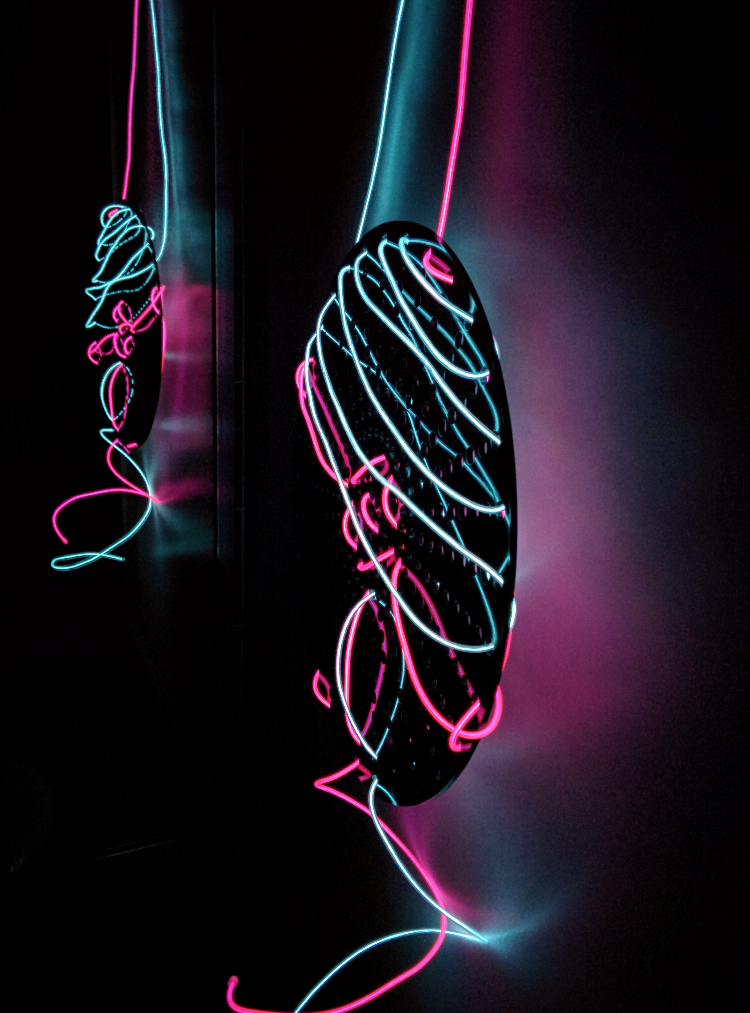
But in the end the idea works, perhaps with some managed expectations. I think I might try to iterate a bit on this to help manage the wire more, but I like the effect overall in a dark room.
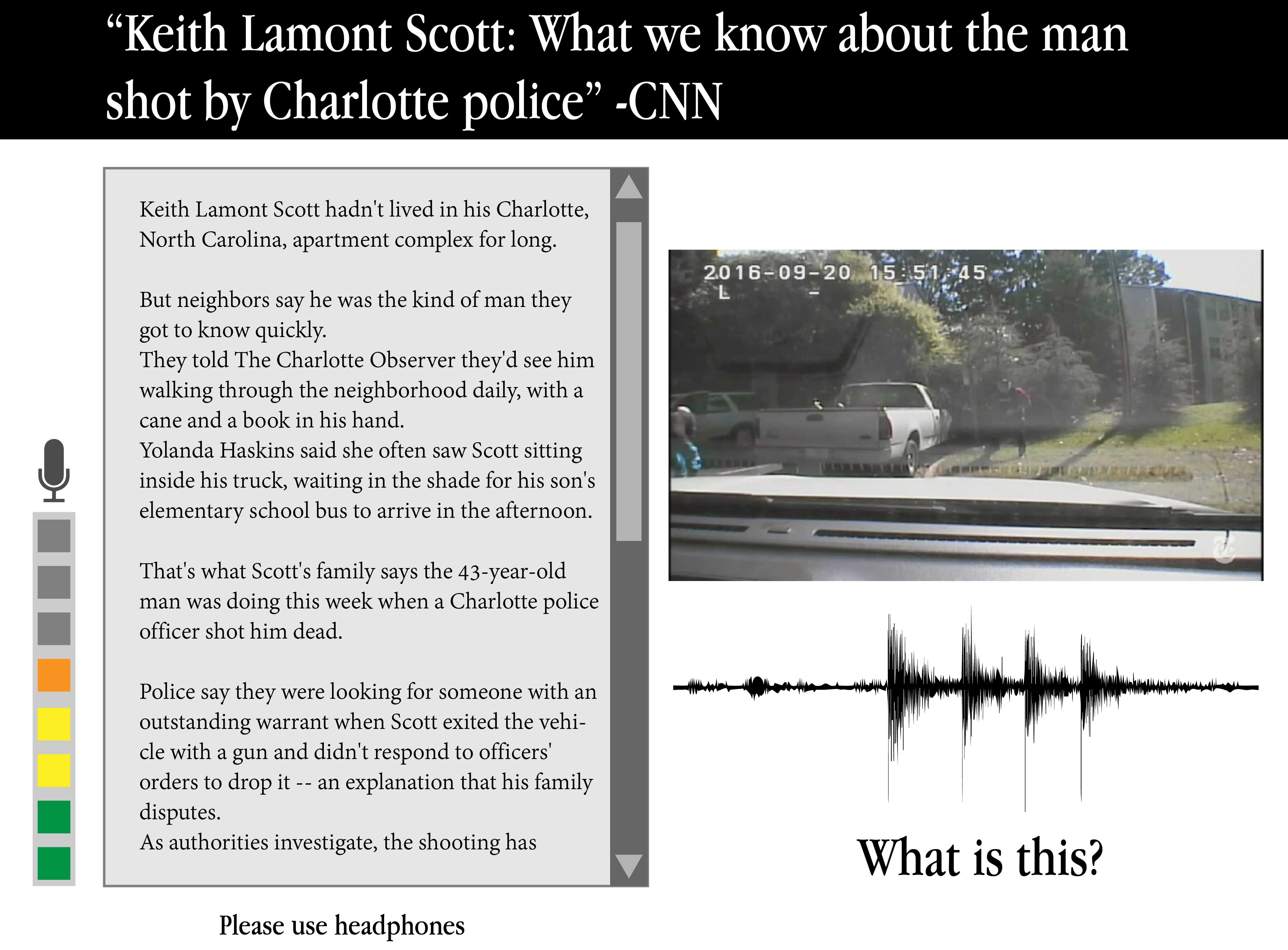
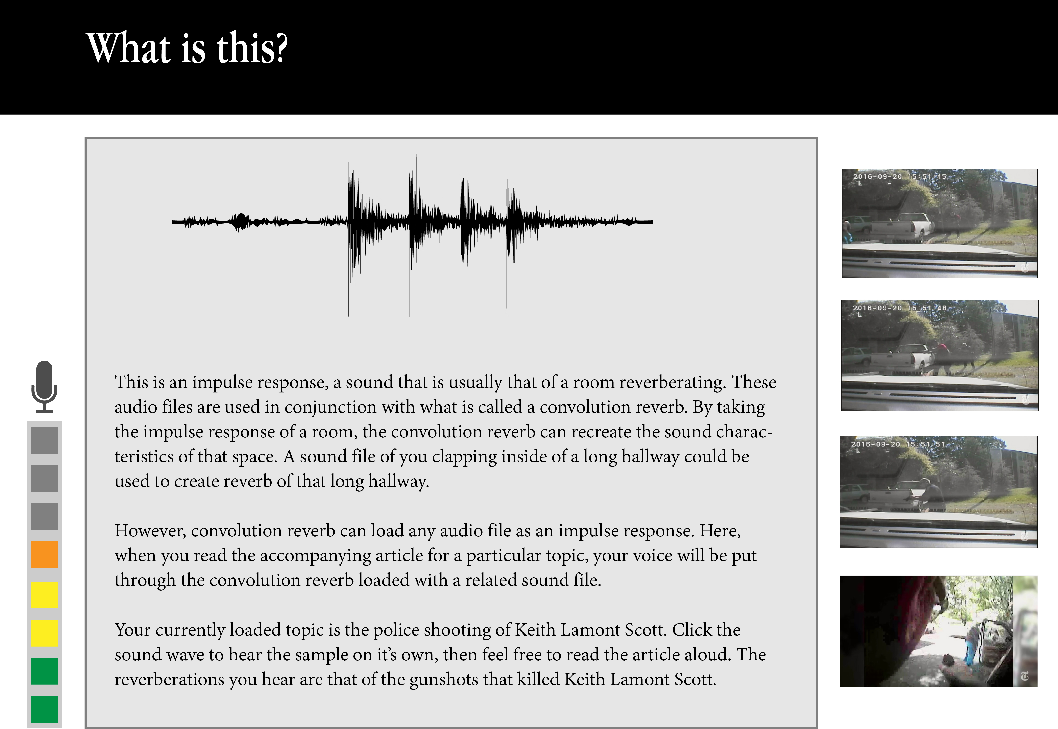
My concept for the ICM final project is an installation piece that uses the noises of important, controversial, political and or emotional issues to create reverberations (echos). A user would be prompted to read about these issues into a microphone, and then listen via headphones to their own words, put through the reverberations of these issues.
Use charged or confrontational news stories in an attempt to create a different kind of empathy using emotionally charged impulse responses in a convolution reverb system. The user will be effected, aurally, by the topic. Forcing to hear one’s self through the effect of the topic may perhaps create a different kind of connection. However, a sense of distance is still maintained. The user speaks with their own voice, accompanied by the echos of something serious.
“Political tools”?
Is a reverb supposed to be accurate? Is a tool not supposed to have an agenda? Is there a place for an opinionated tool?
Sound as data, data as agenda.
I am interested in data auralization, as opposed to data visualization, as a method of conveying data. While there are more utilitarian and straightforward aspects of this technique, I see no reason not to make a statement with the sound data and present it in a manner that unapologetically conveys a message.
“Hard to talk”
Depending on the impulse response in question, it could be difficult to hear or read the story given. However, these are difficult stories to hear or read without any audio effects at all.
Issues
Education
The conceptual core of appreciating the work is as much about communicating technically what is a convolution reverb, as it is about the metaphor of using it. Educating the user about convolution reverb before the artistic confrontation is necessary, but presents it’s own UX challenge.
Copyright
I am not entirely knowledgeable on the specific details of how sampled/remixed/referenced media is ethically and legally implemented in media art on a professional level. Time needs to be allocated towards getting permission to use works and researching publicly licensed media.
Topics
Are there topics that may be inappropriate for use? Would certain topics allow for easier media collection? Are there topics that may lessen the potential for harmful artistic appropriation (climate change could be less appropriative, when focused on animals or objects).
I had some great feedback after presenting in class, and will definitely try to refine the messaging and specific UX flow over the next few days in order to get started.
Our task for this week in intro to fabrication was to make multiples of a design (at least 5). I have had an idea for what I’ve called a “percussive wand”, a tool that allows a DC motor and attachments to be used as a musical instrument. At first I thought about the multiples challenge in terms of something that would fit as a set of things. However, it occurred to me that if I wanted to do user testing of a prototype, it might be good to have multiple prototypes to give out.
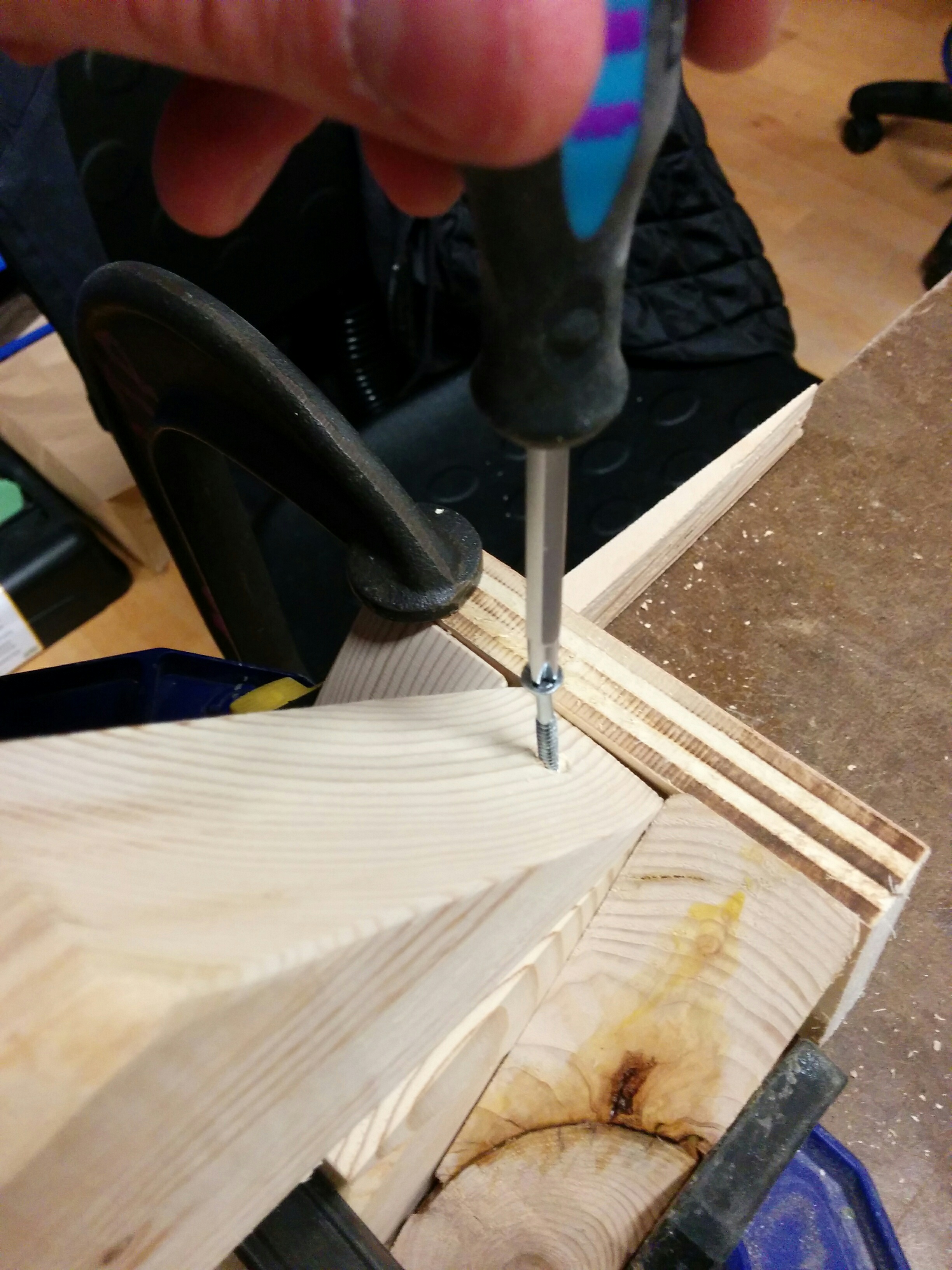
Credit Joe Mango for help thinking about how to screw in the handle
Starting Material
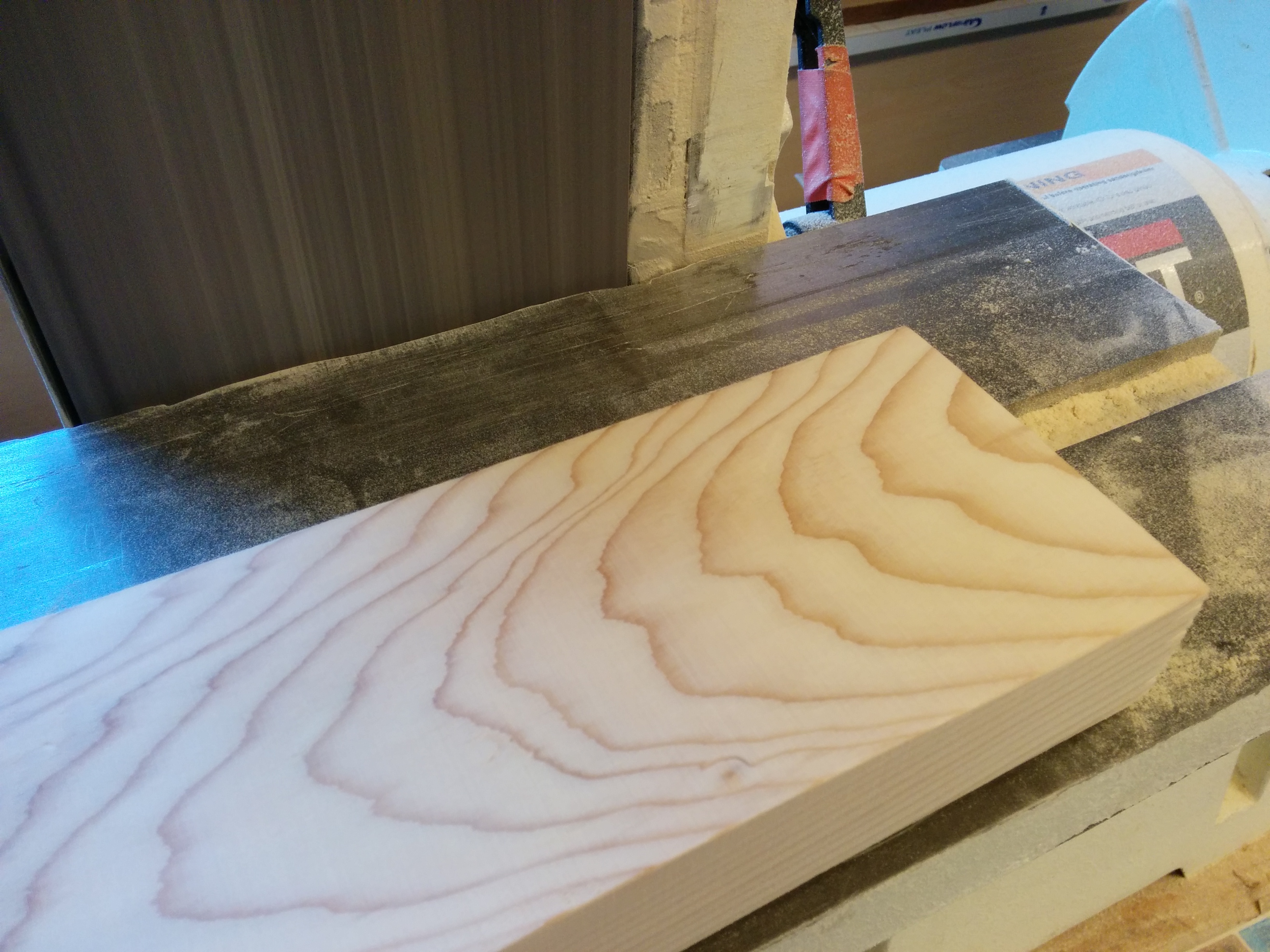
I went to Midcity Lumber and picked up 8ft of 2×4 pine. I figured that each wand would be approximately 1ft long, so to acheive 5 solid pieces I bought more than I needed.
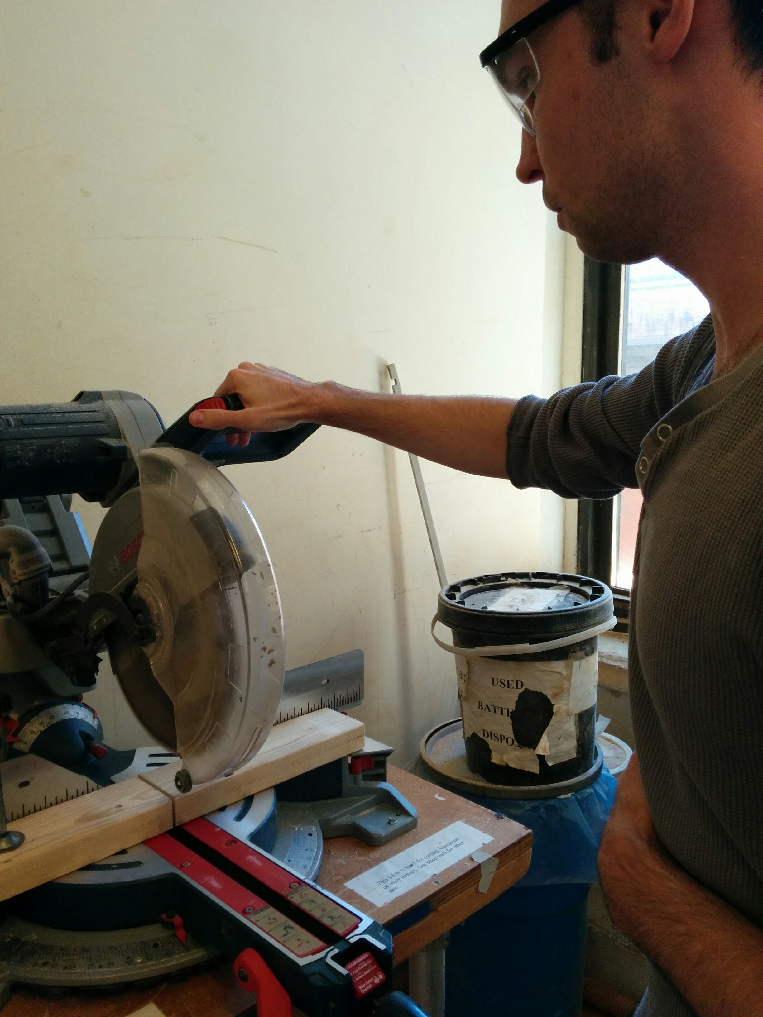
Process
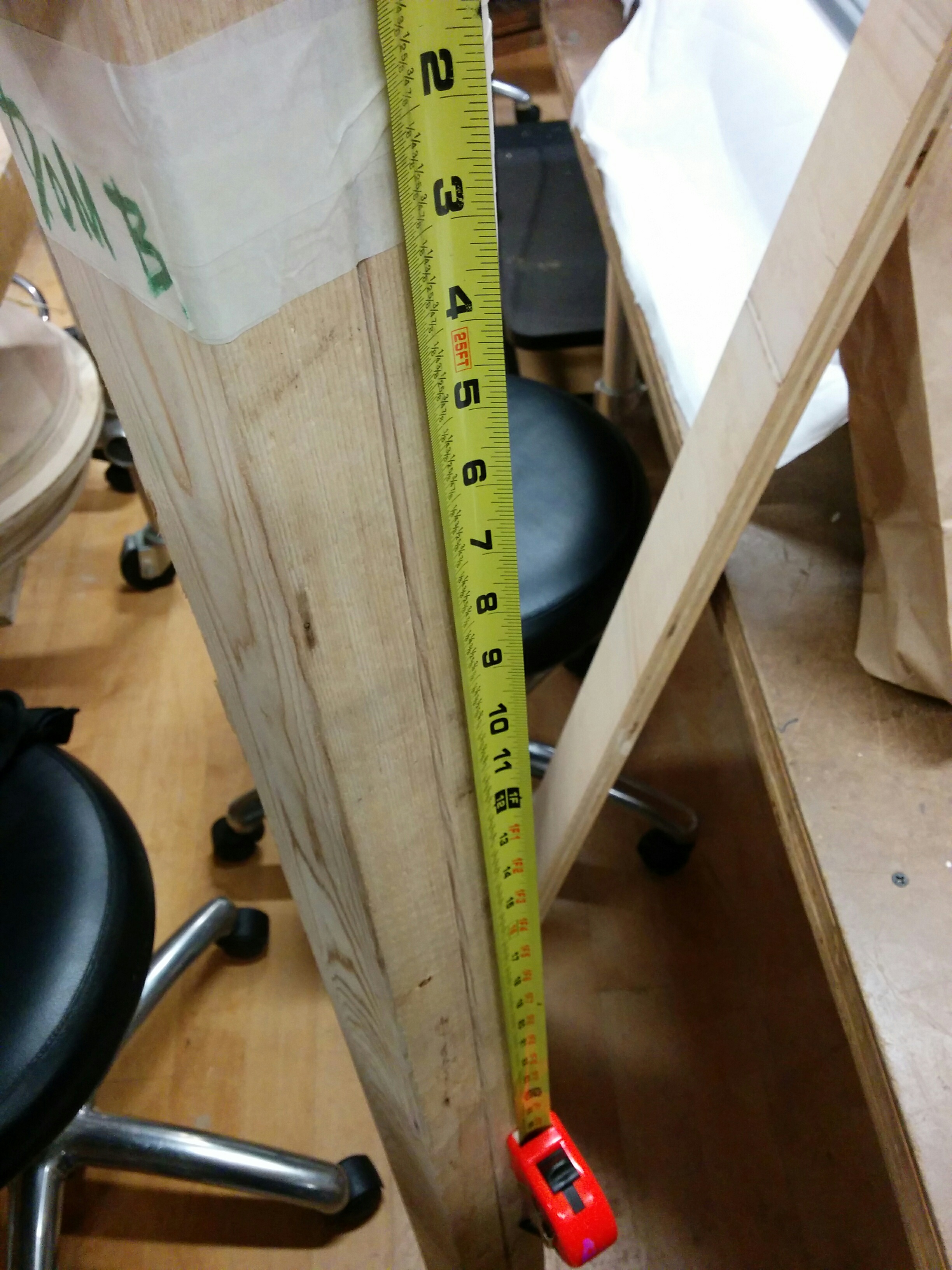
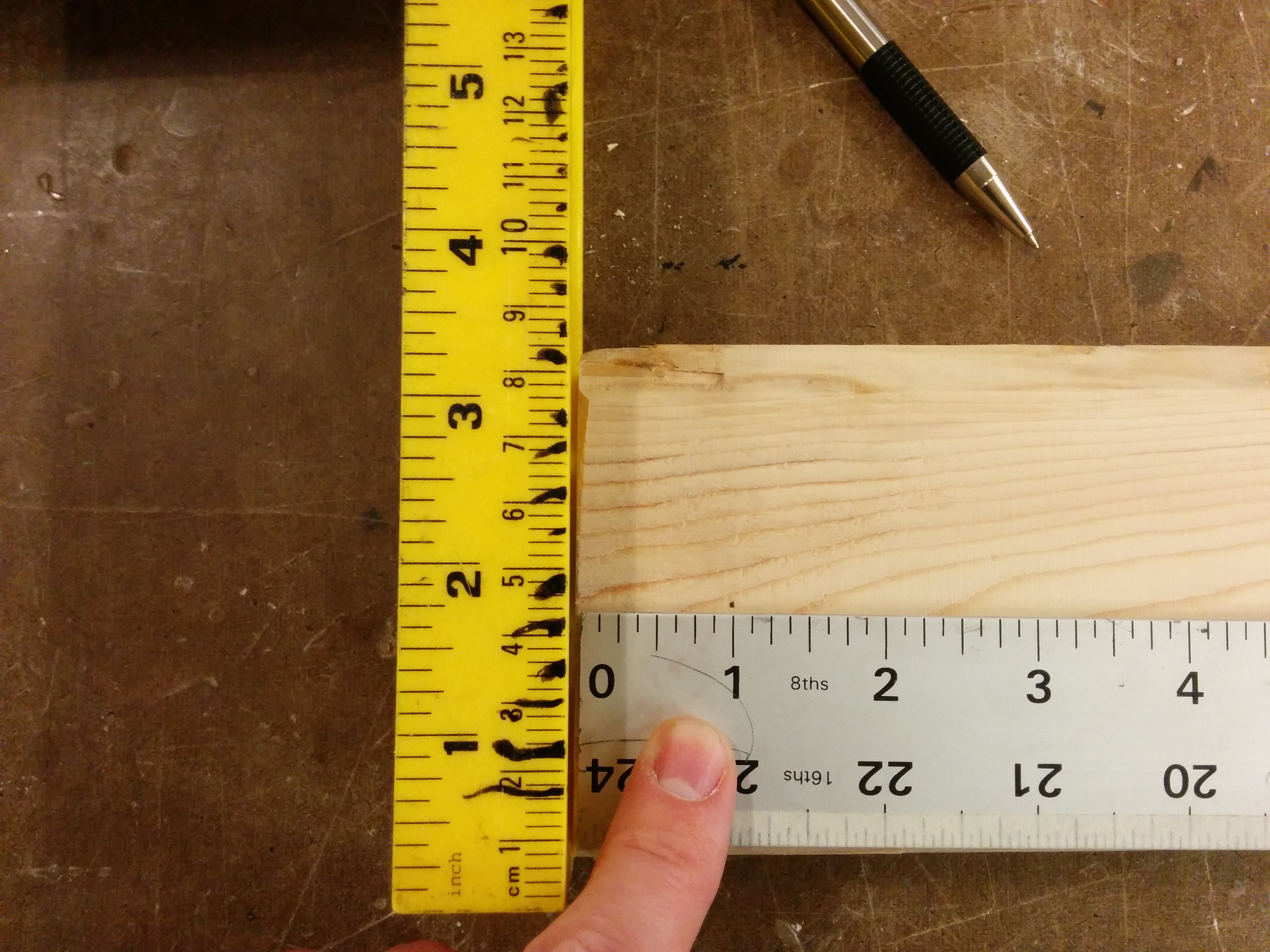
Midcity does $2 a cut. For the sake of my fellow MTA riders, I had the 8ft cut into two pieces. When I returned to ITP, I started measuring initial cuts. From 4ft to 1 ft pieces.
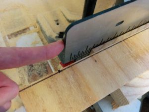
But the Midcity cuts weren’t perfect. I had initially thought I would be clever and use the mitre saw to cut both pieces at the same time. However, after marking the middle point of both pieces, I realized that they weren’t *exactly* the same length. It wasn’t that much more work to individually cut each piece, so I opted for that.
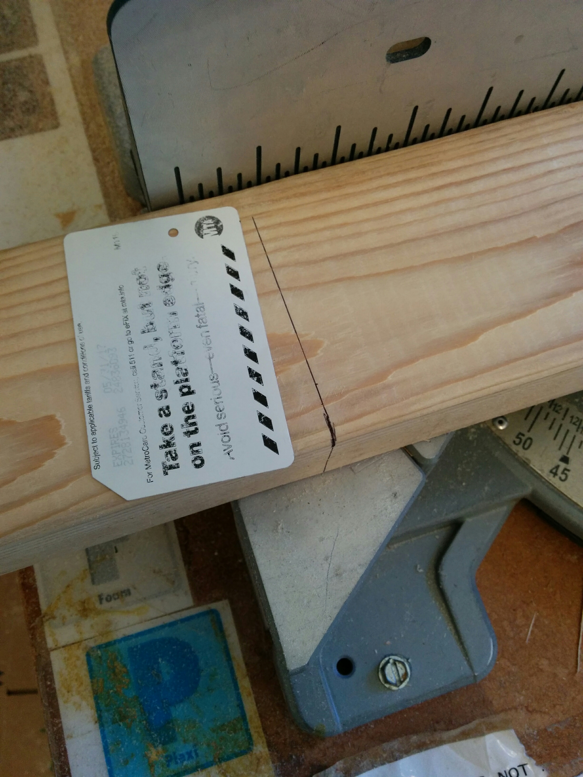
A little improvisation when I needed a straight edge to draw the cut…
Will definitely need to sand these! I knew cuts were rough, but I was surprised at the amount of splintering.
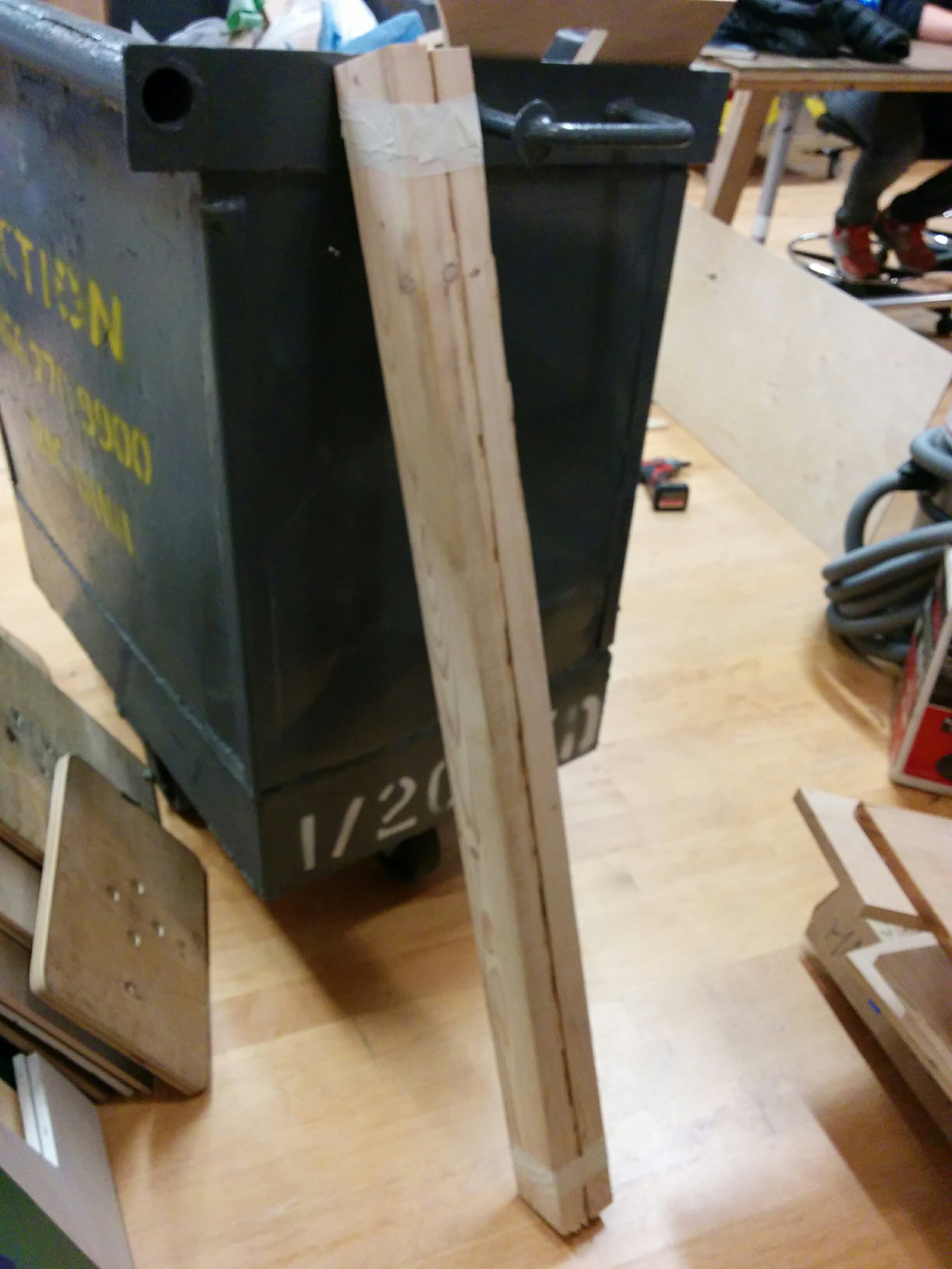
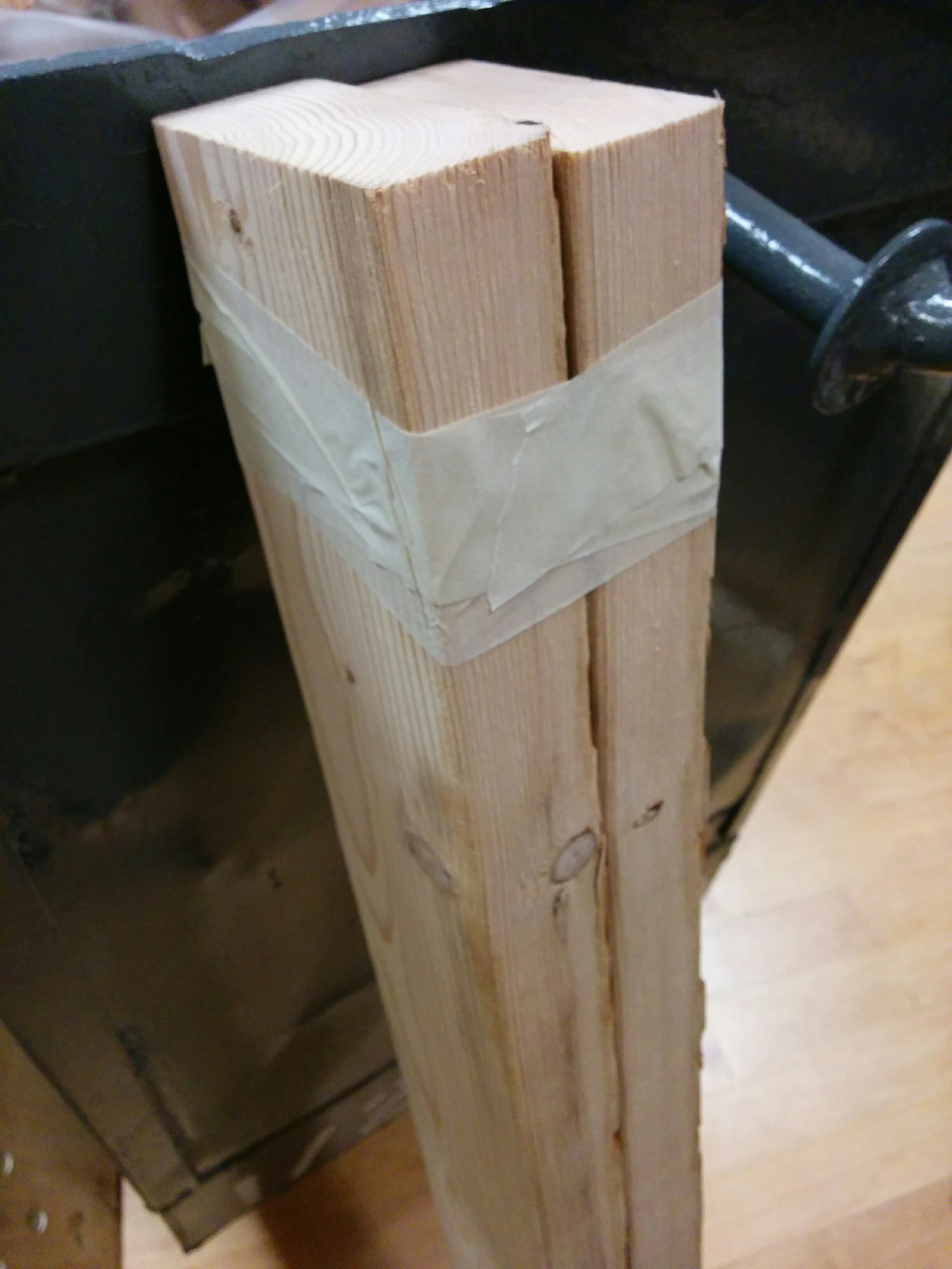
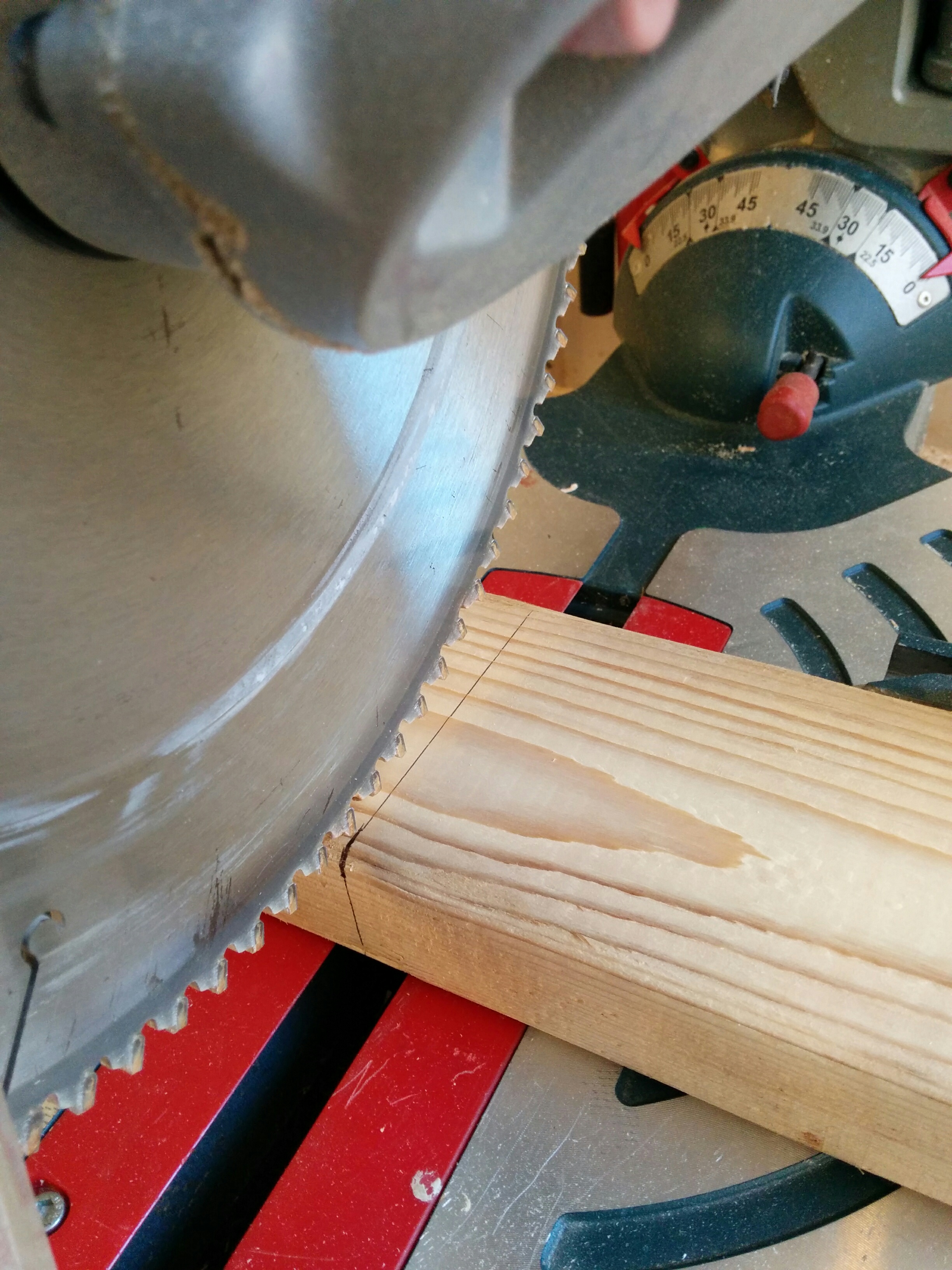
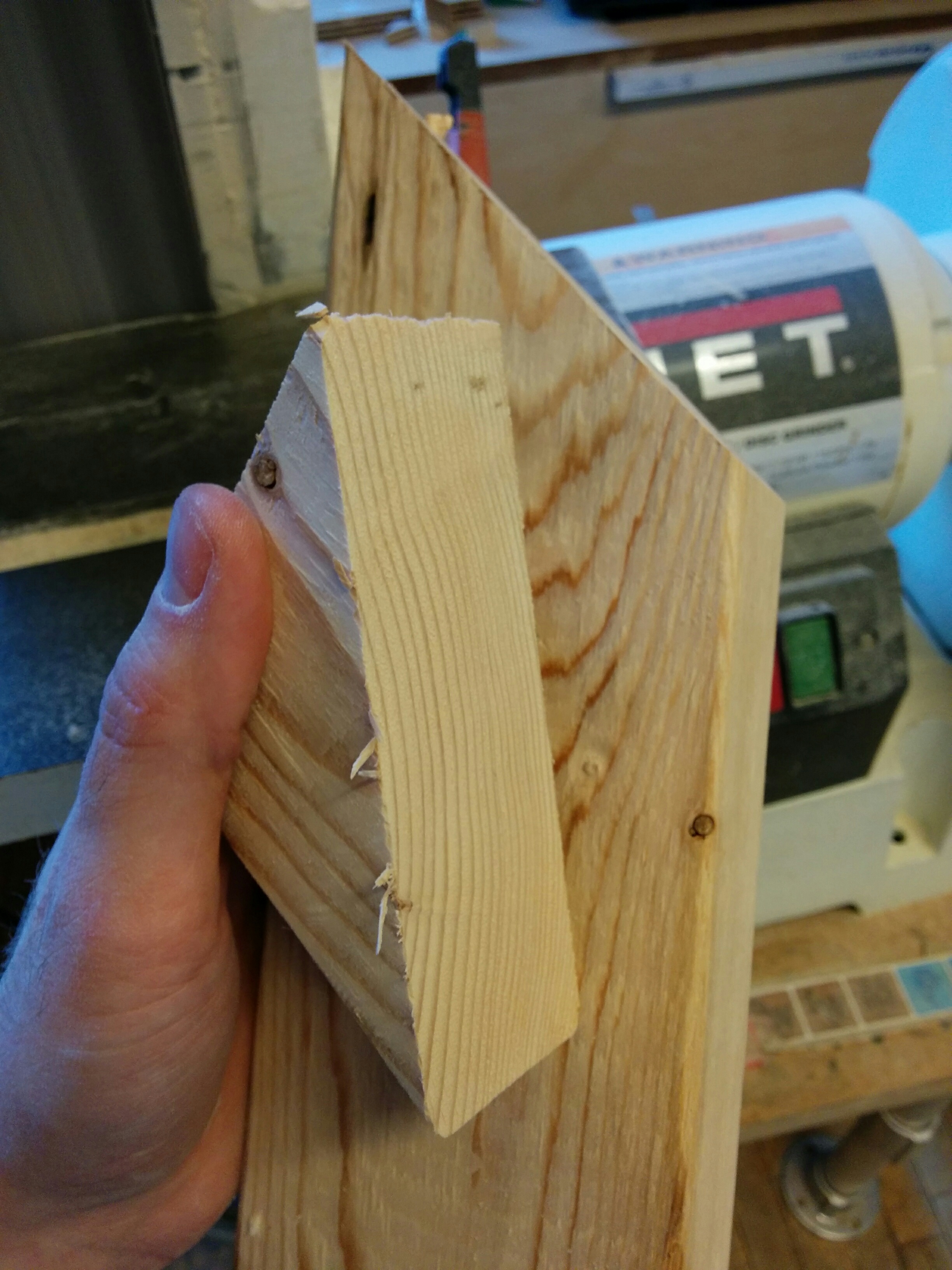
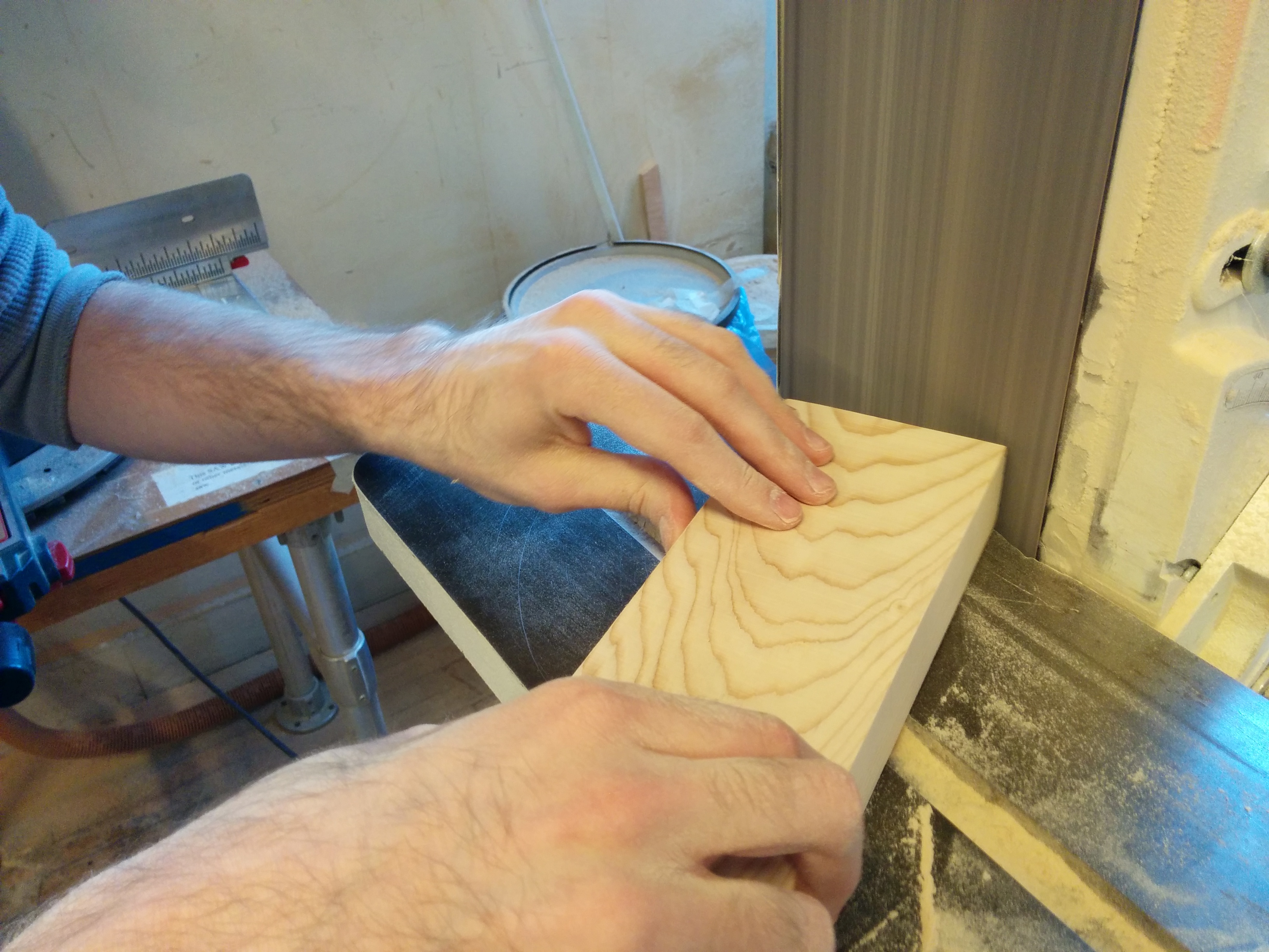
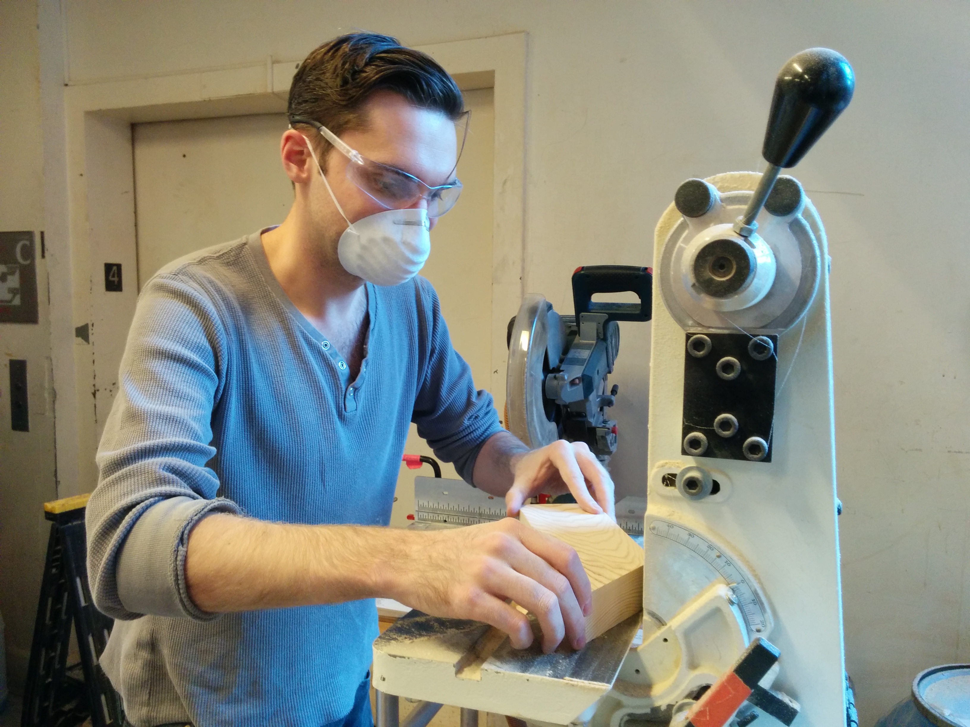
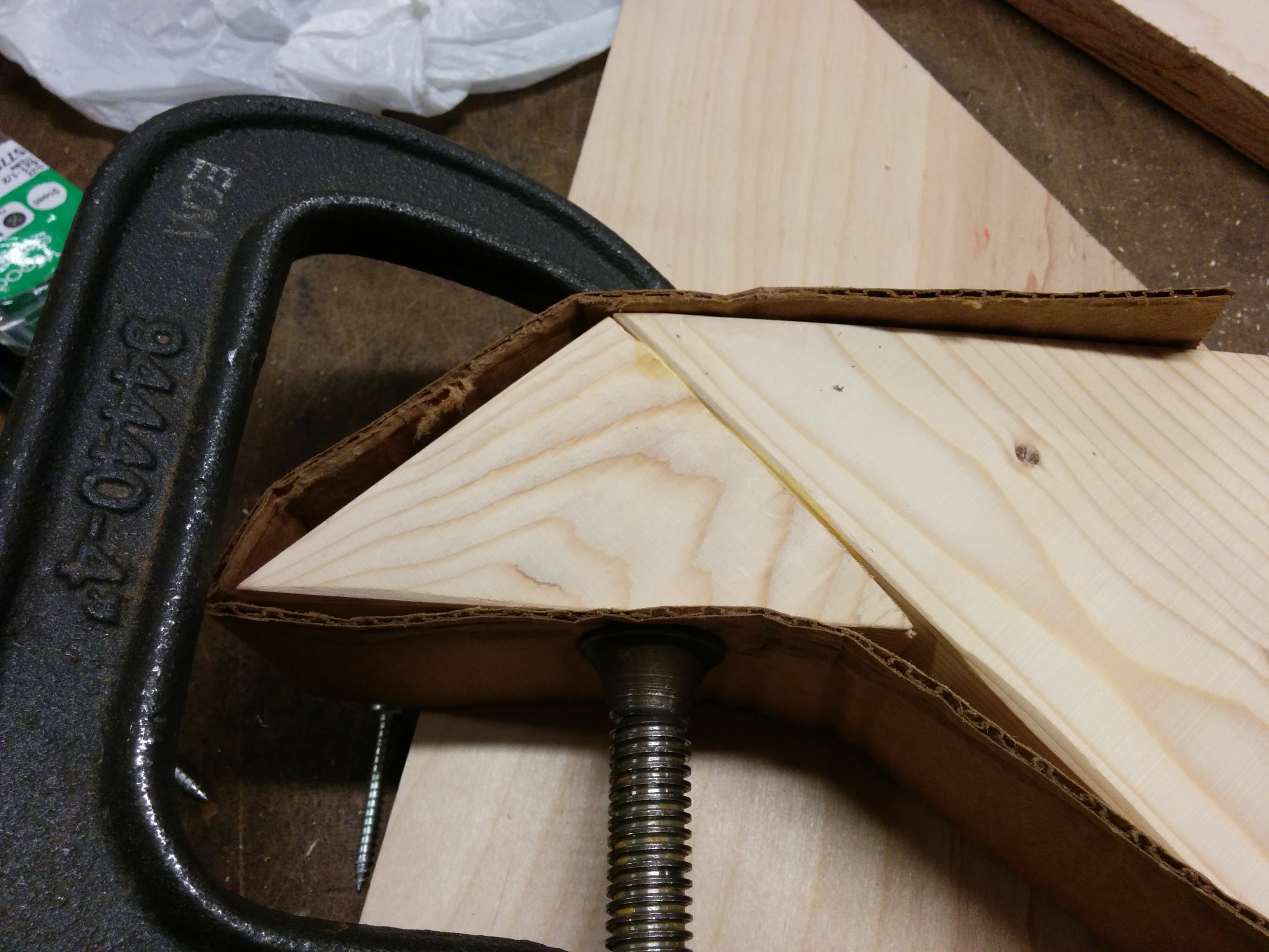
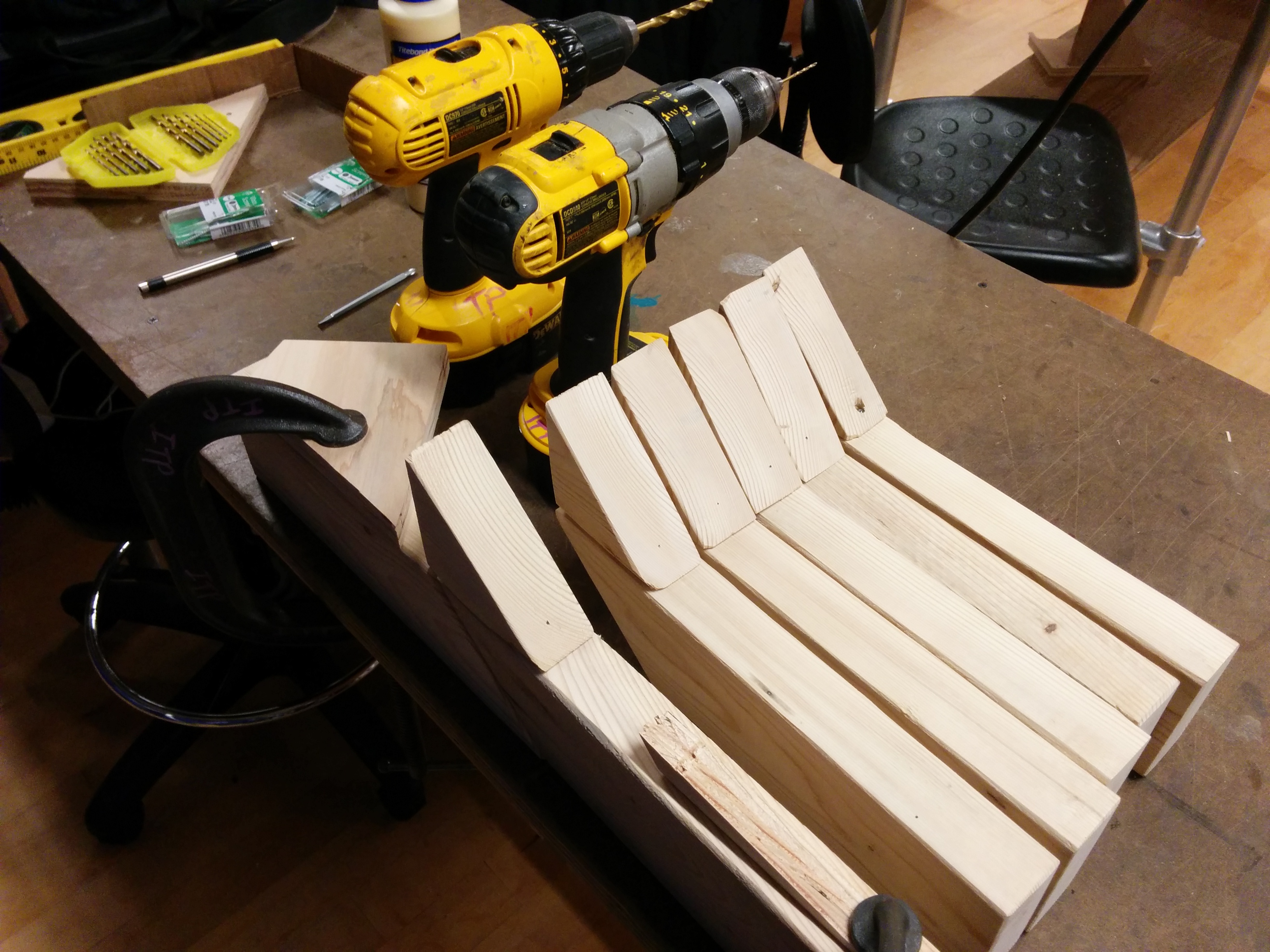
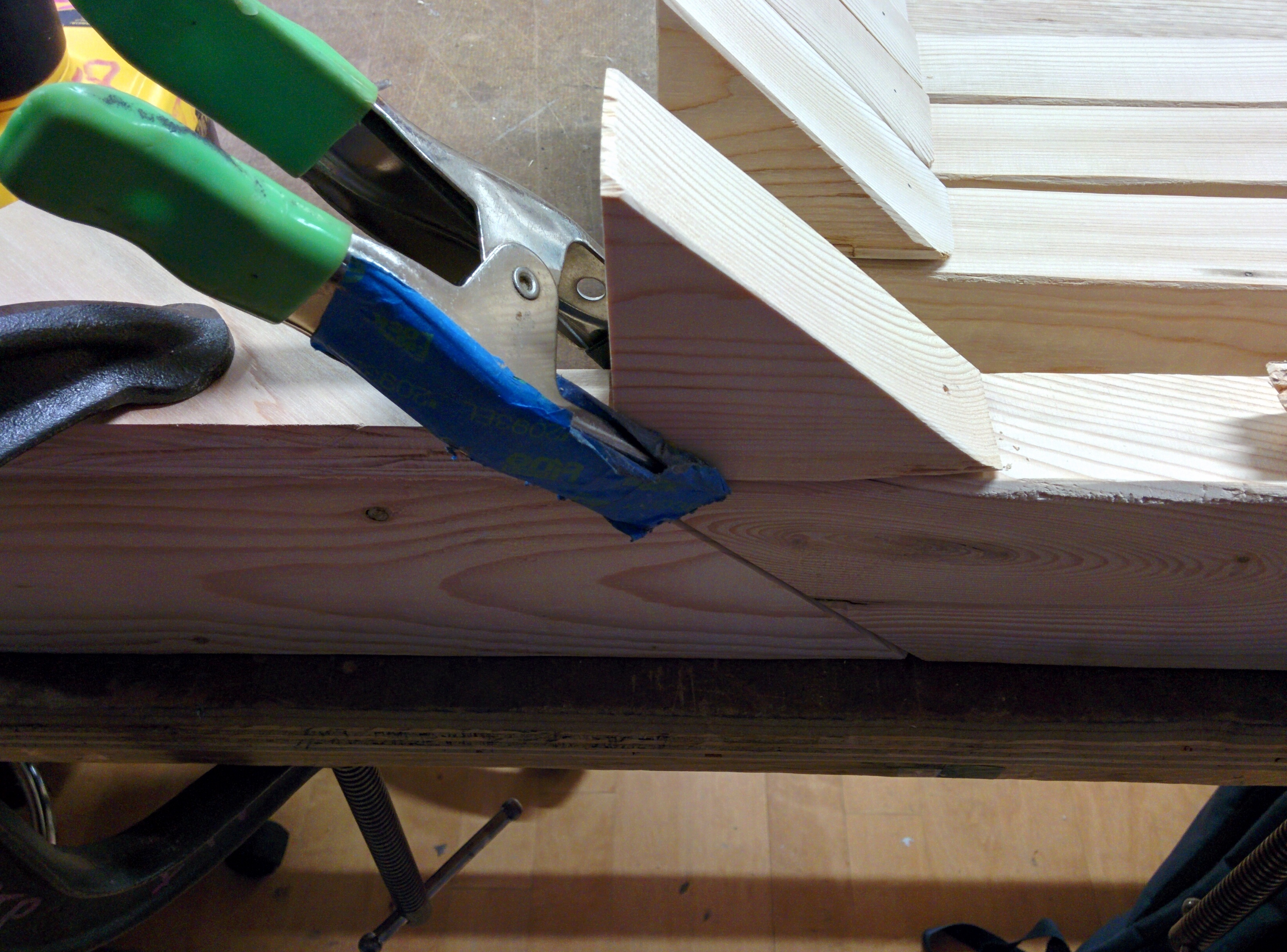
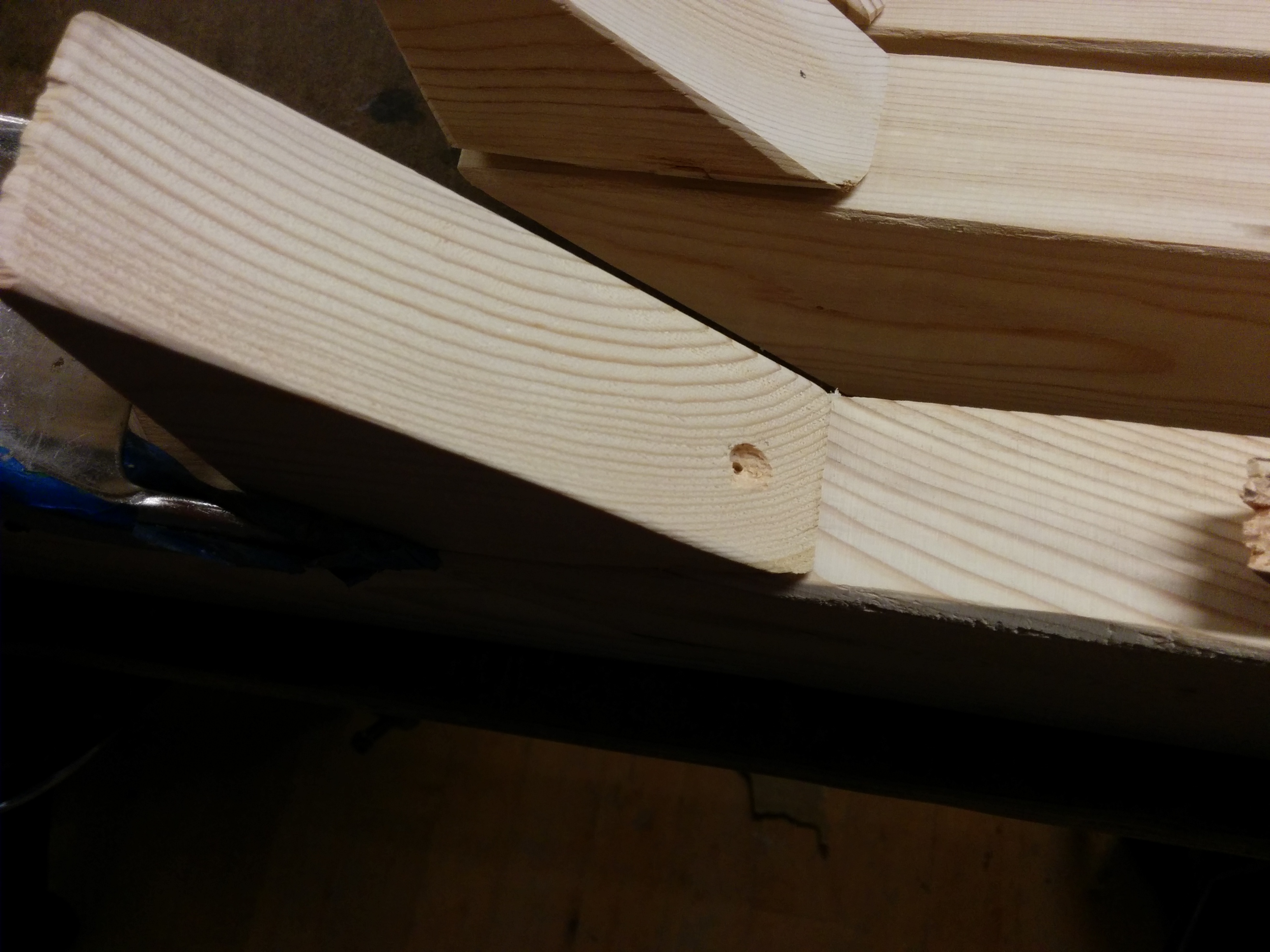
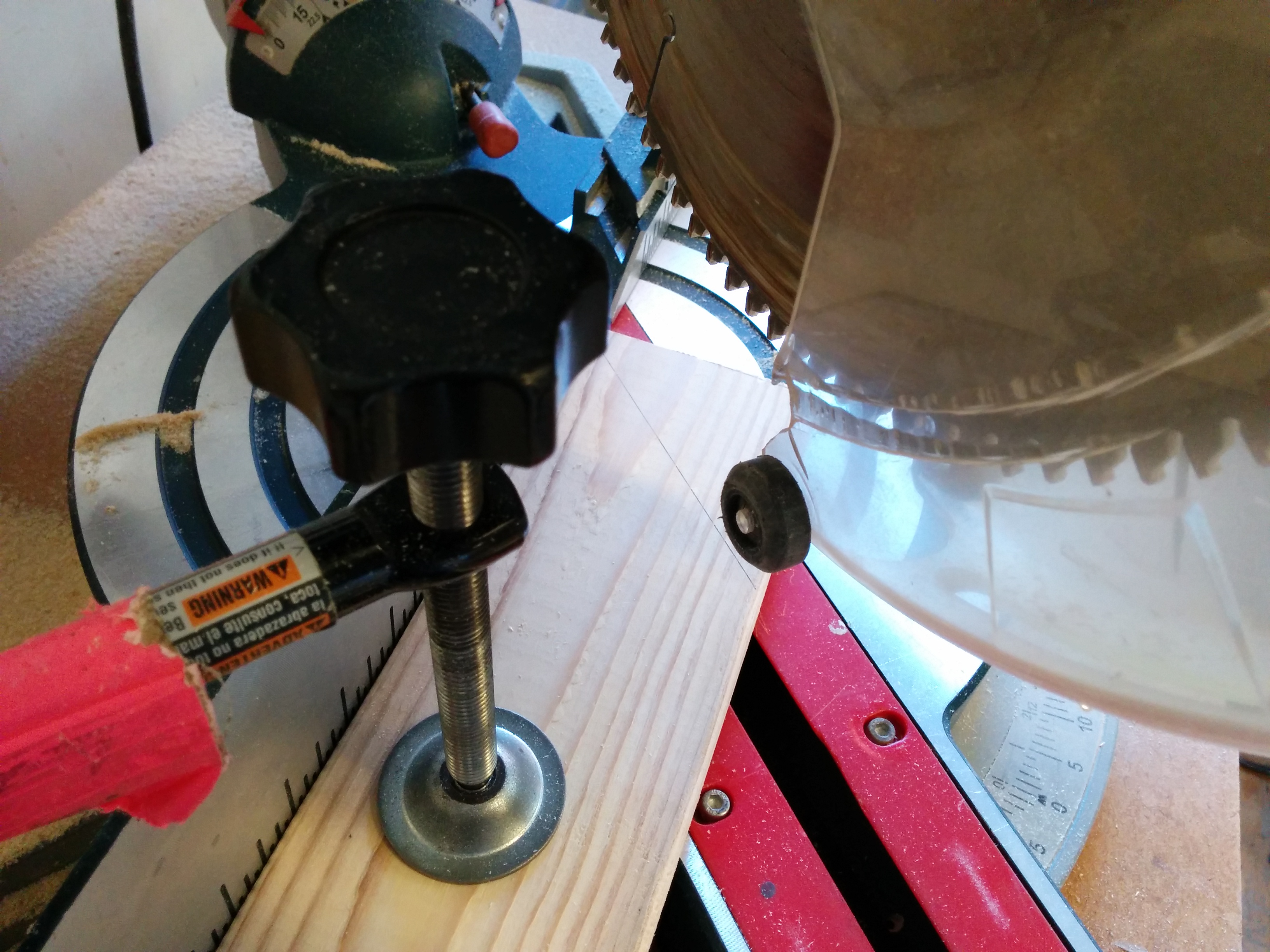
Moving onto the 45 degree cuts. This creates the handle for each wand, allowing a sloped end that meets up with the handle. Additionally, it saves material.
Weird… didn’t notice those little dots before. Wait! I forgot a shim when clamping!
Measuring out positioning the mitre saw, when I realized… “Hey… this top one moves!”
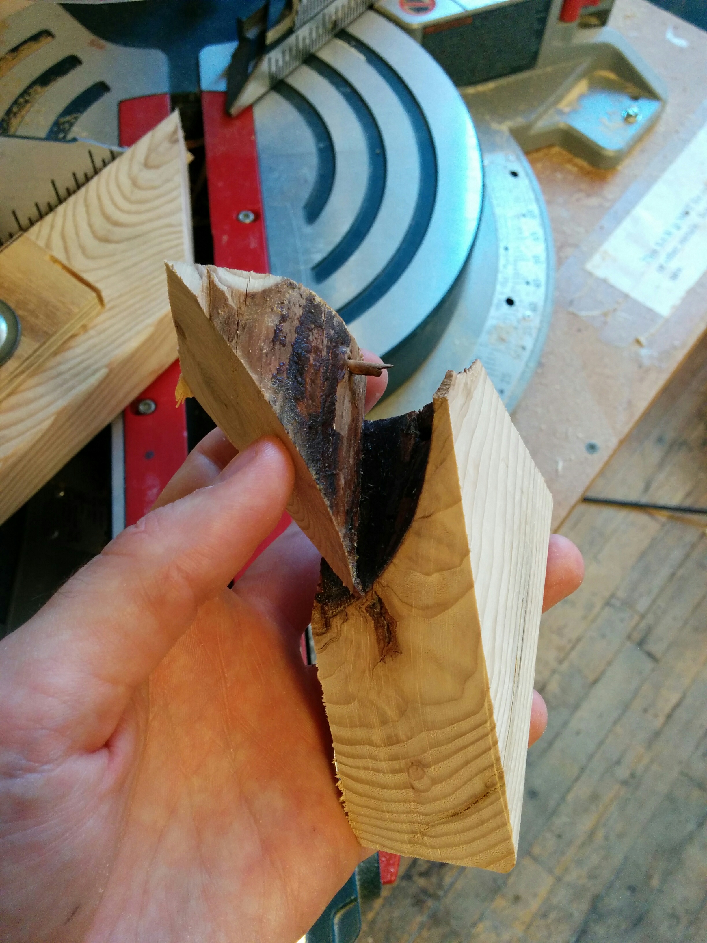
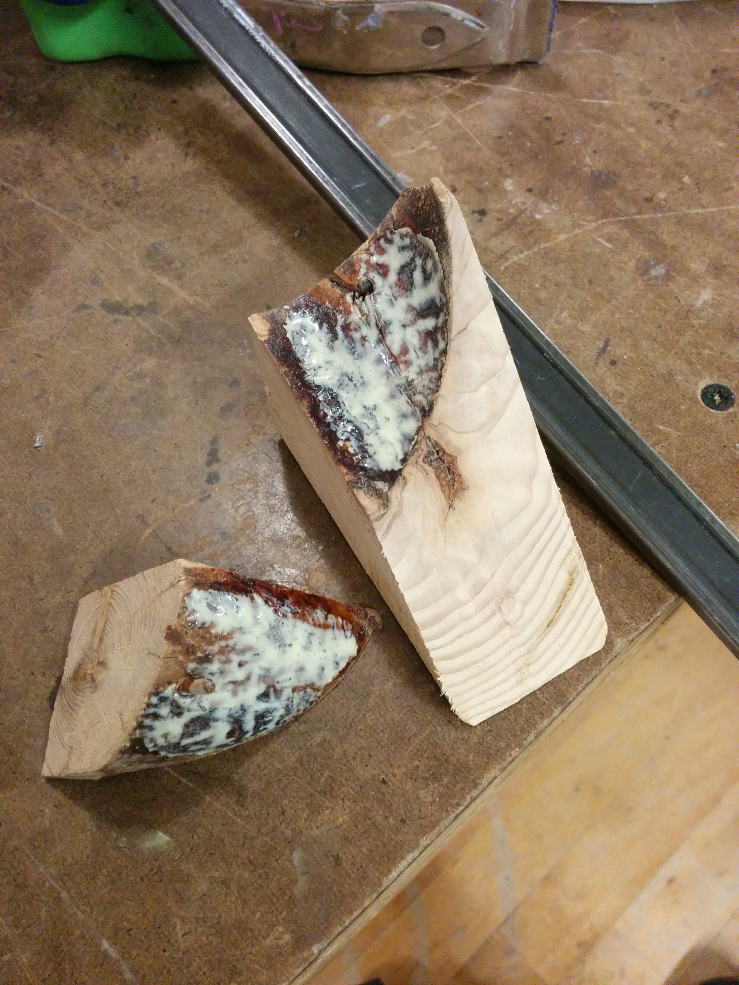
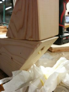
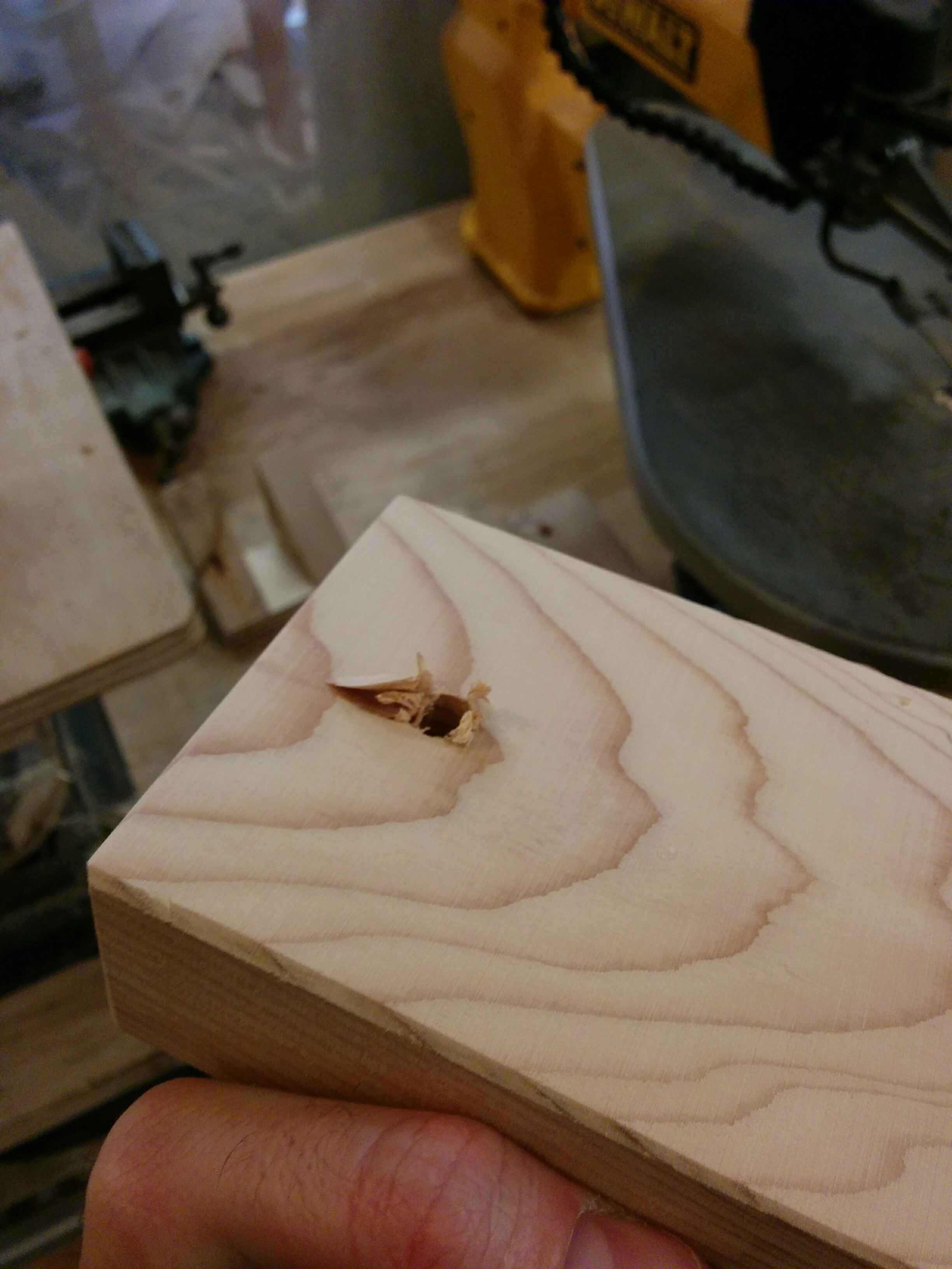
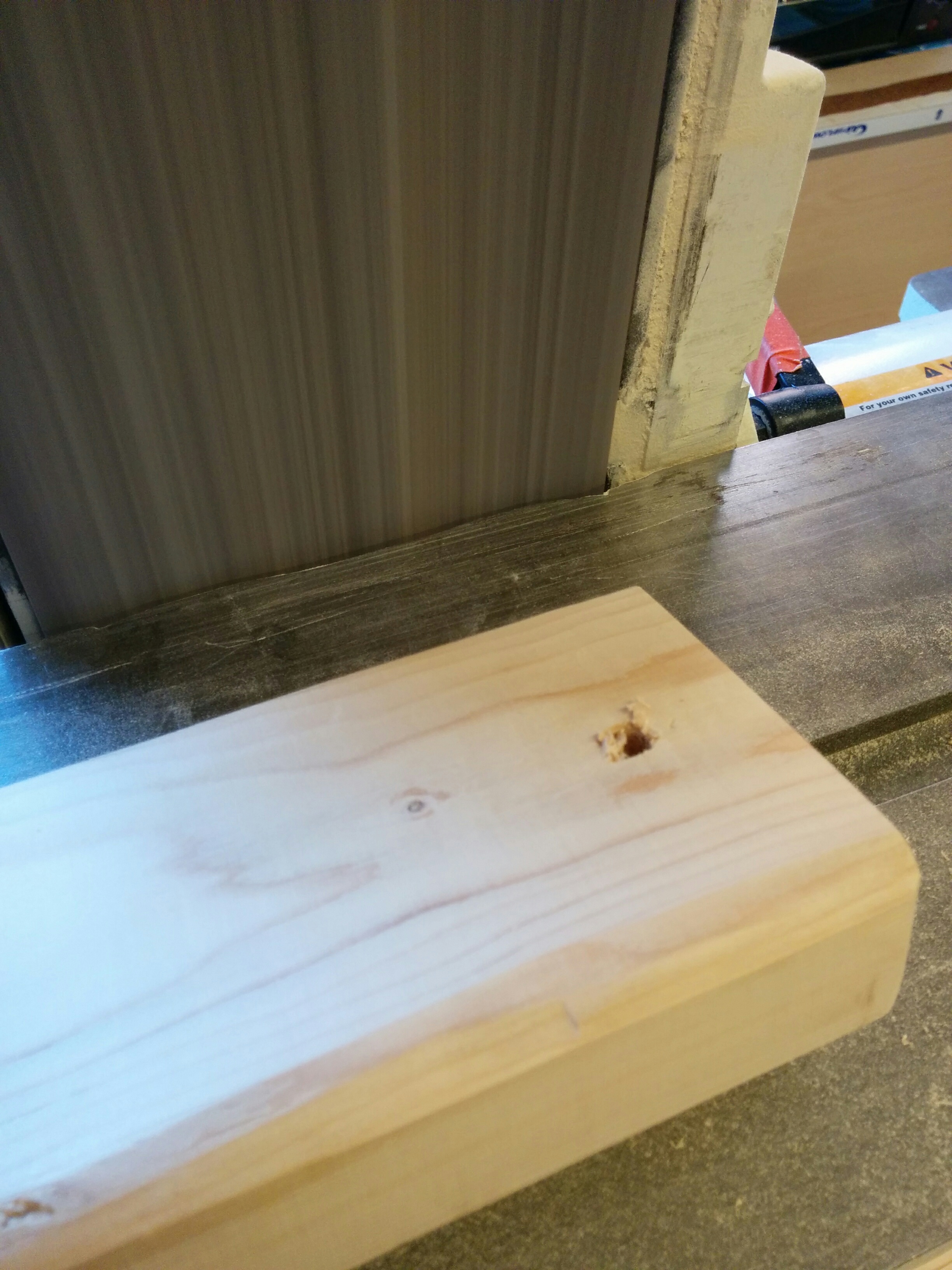
I cut 8 pieces and hit my first Bad Pancake™ ! When sawing into one of the pieces, it seems like I hit or dislodged a gnarly knot inside of the 2×4.
I had my first pieces, and then did an initial sanding.
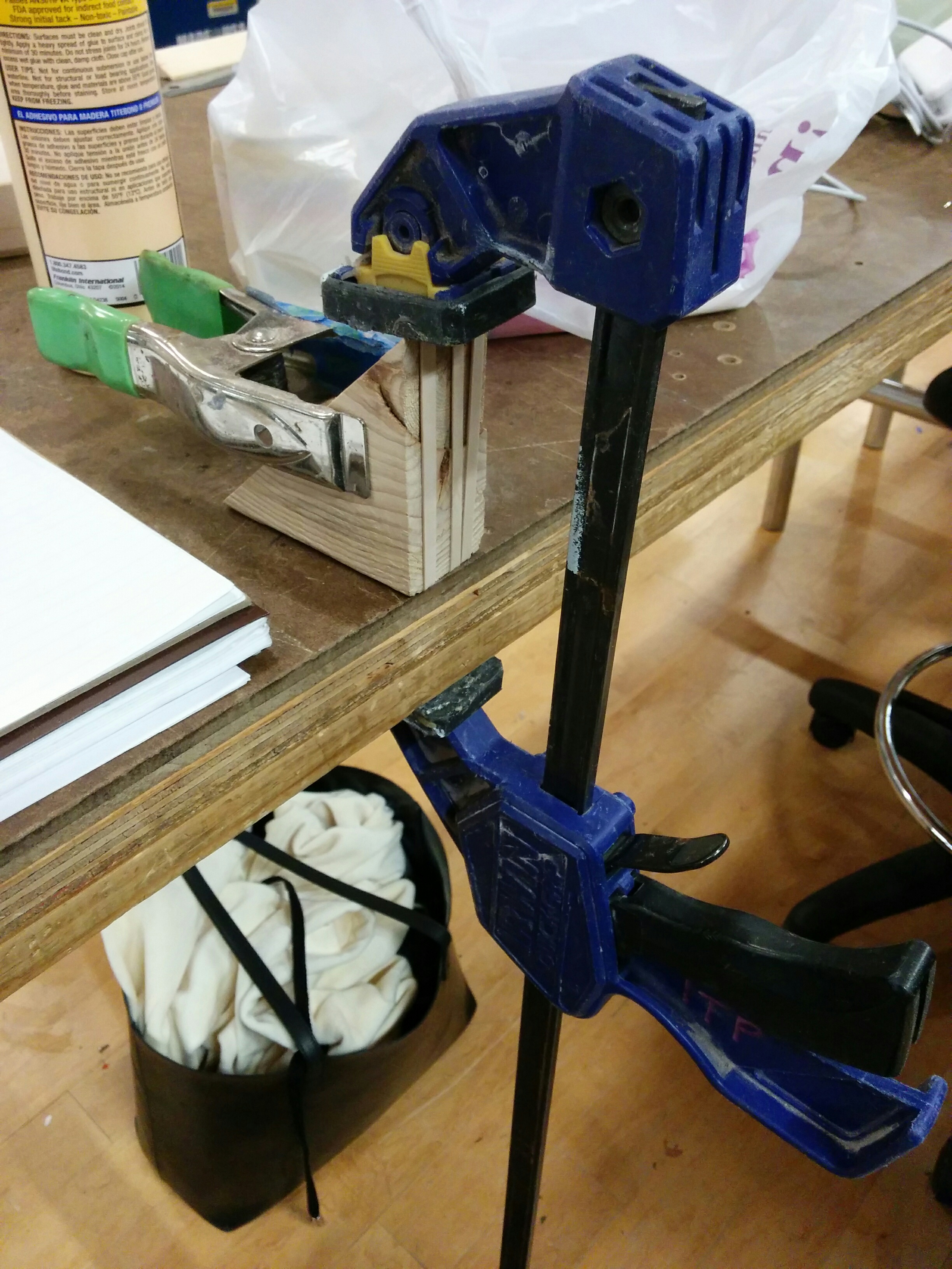
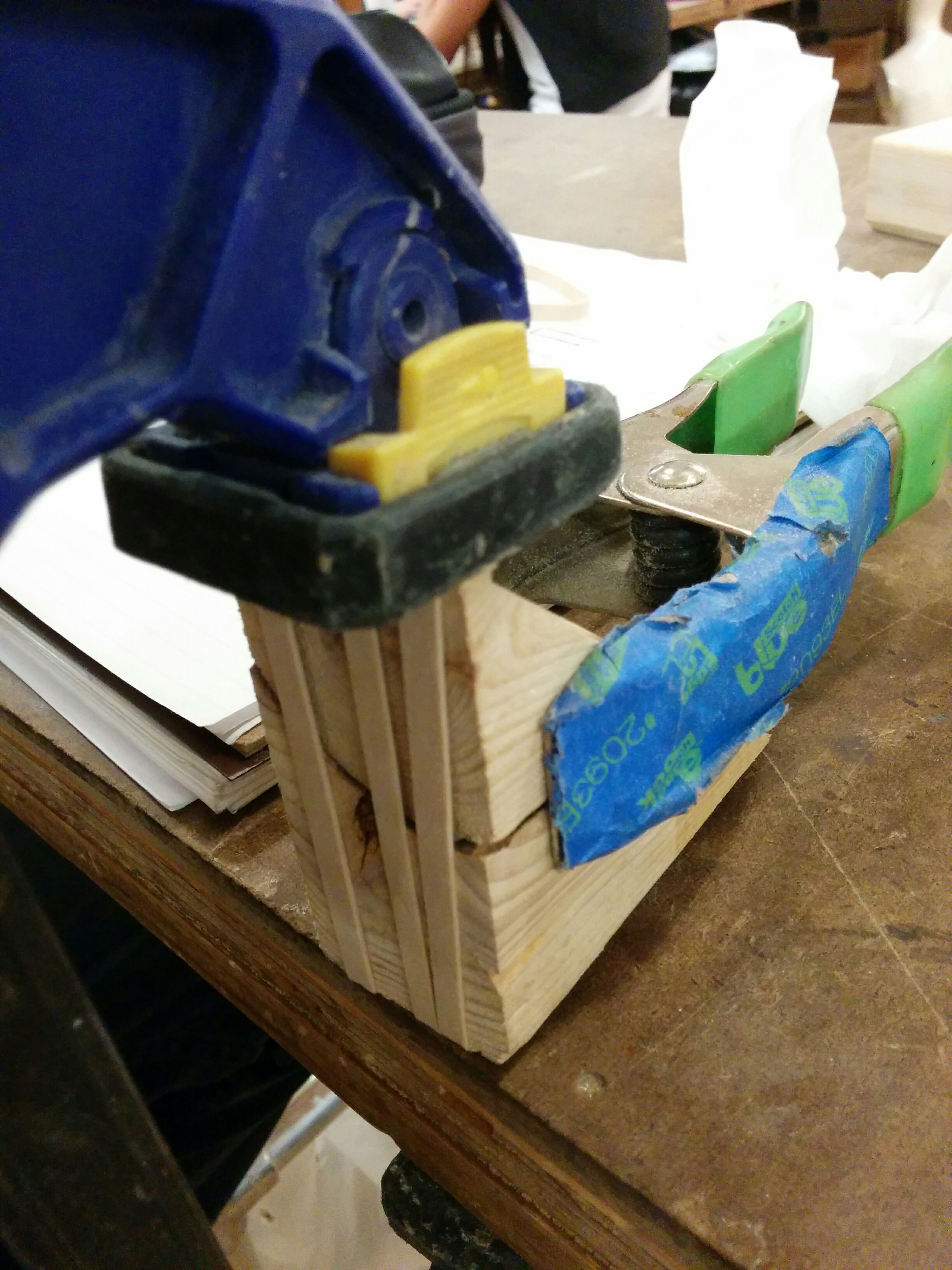
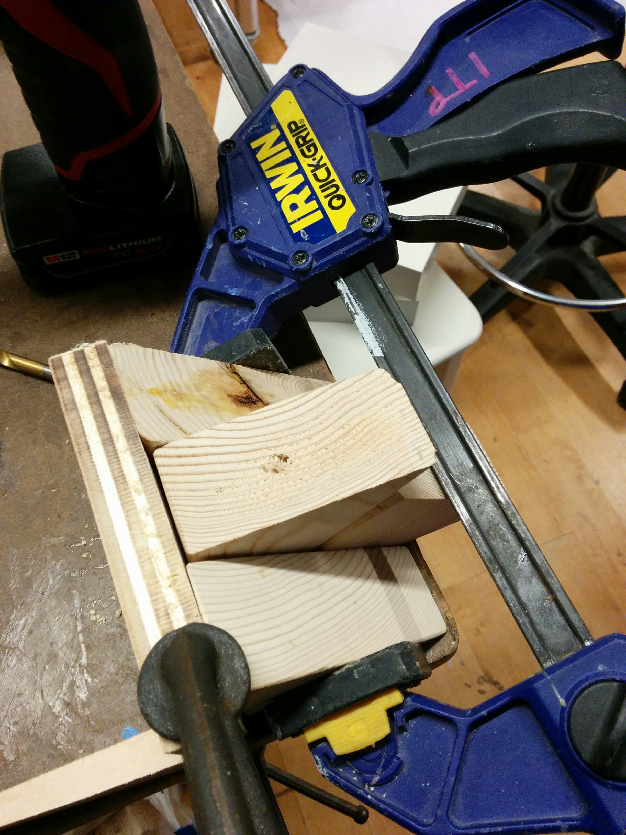
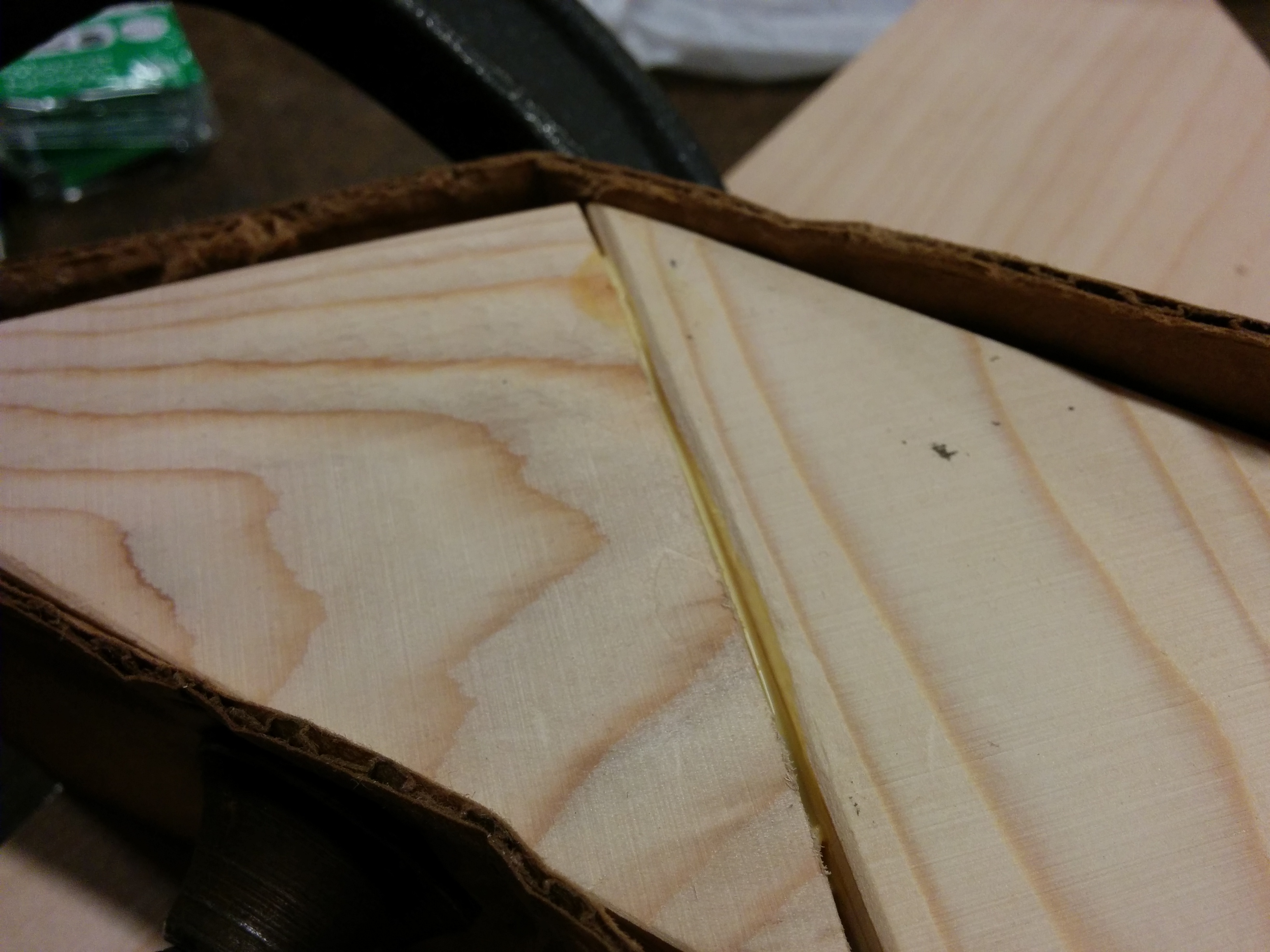
Can I save a pancake? I used some wood glue and clamps to see if it could be salvaged. Had to go with the speed clamp because the heavier clamps kept tipping everything over.
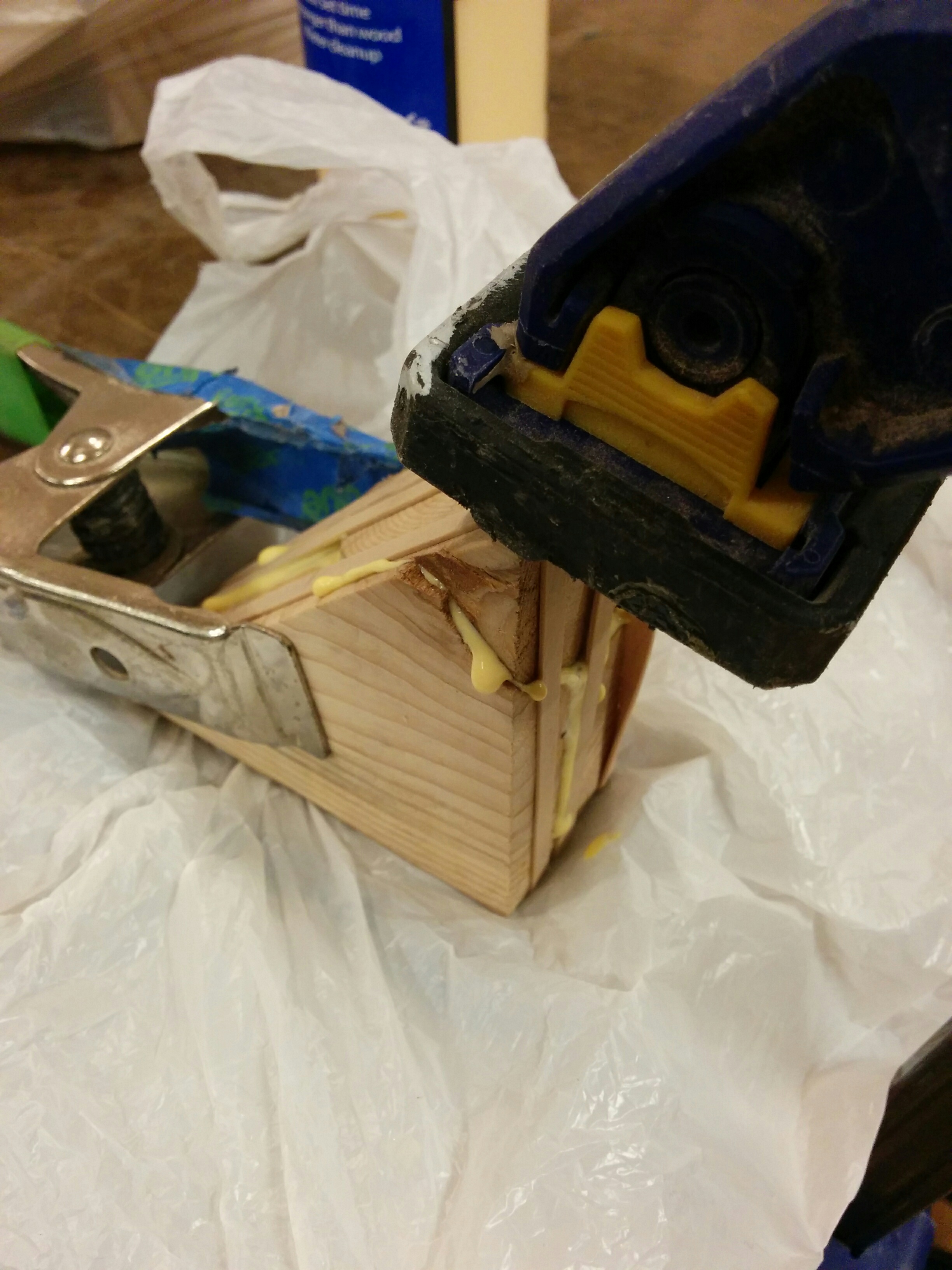
Did it work? Not like this! I waited 30 minutes as directed and the piece came apart pretty easily. I proceeded to totally over compensate, making a bit of a glue-y mess in the process. I waited longer for the clamping and managed to save the pancake! Maybe not the best choice for final production, but perhaps useful in my jig process later.
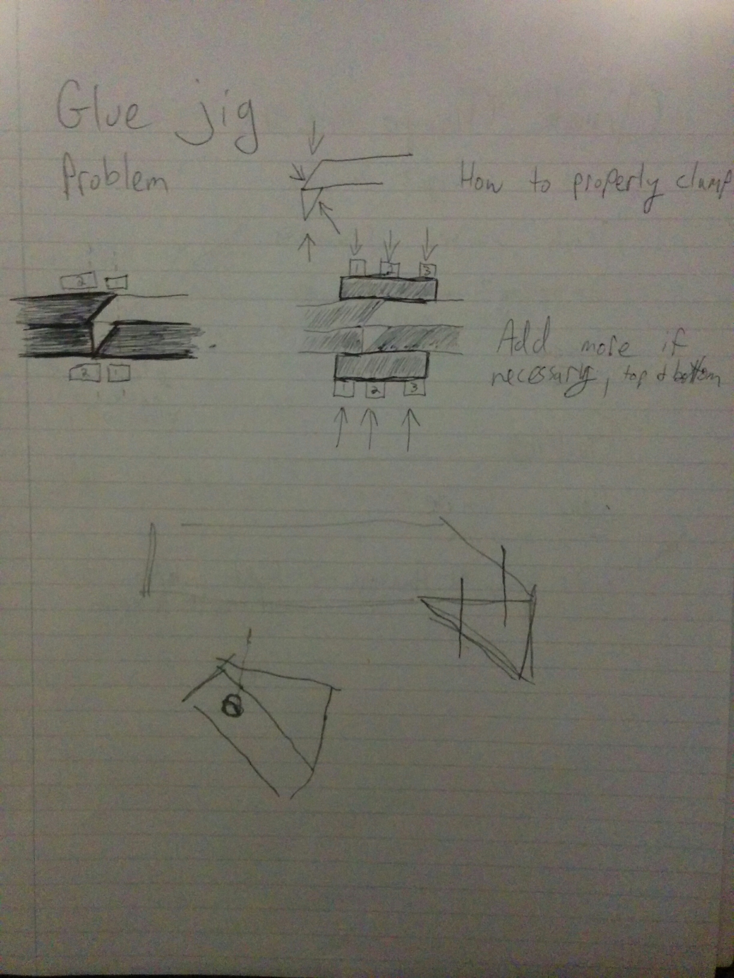
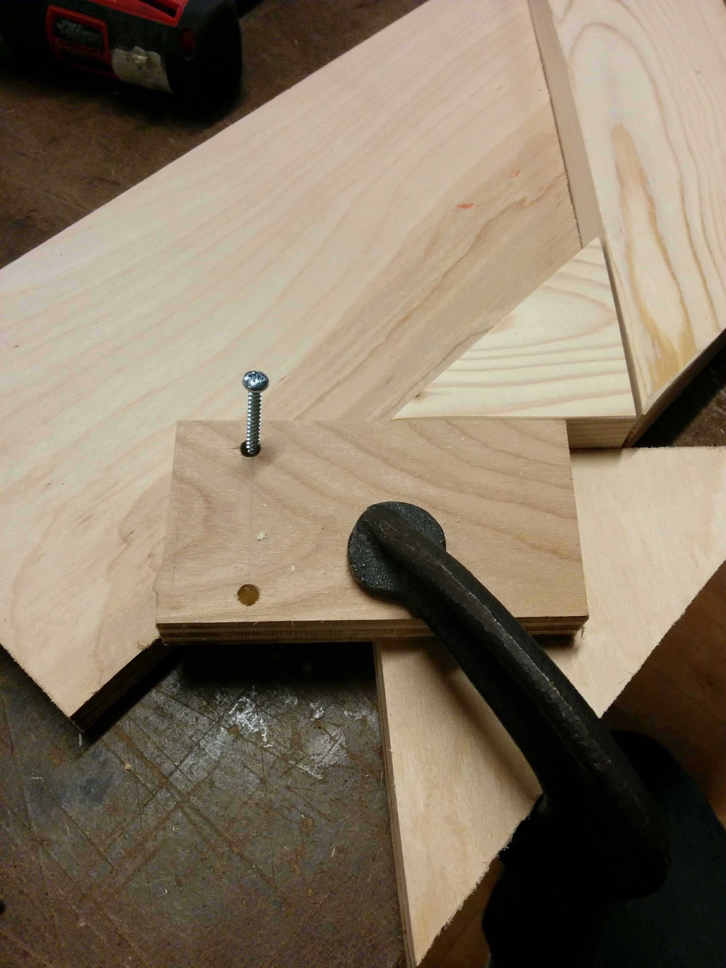
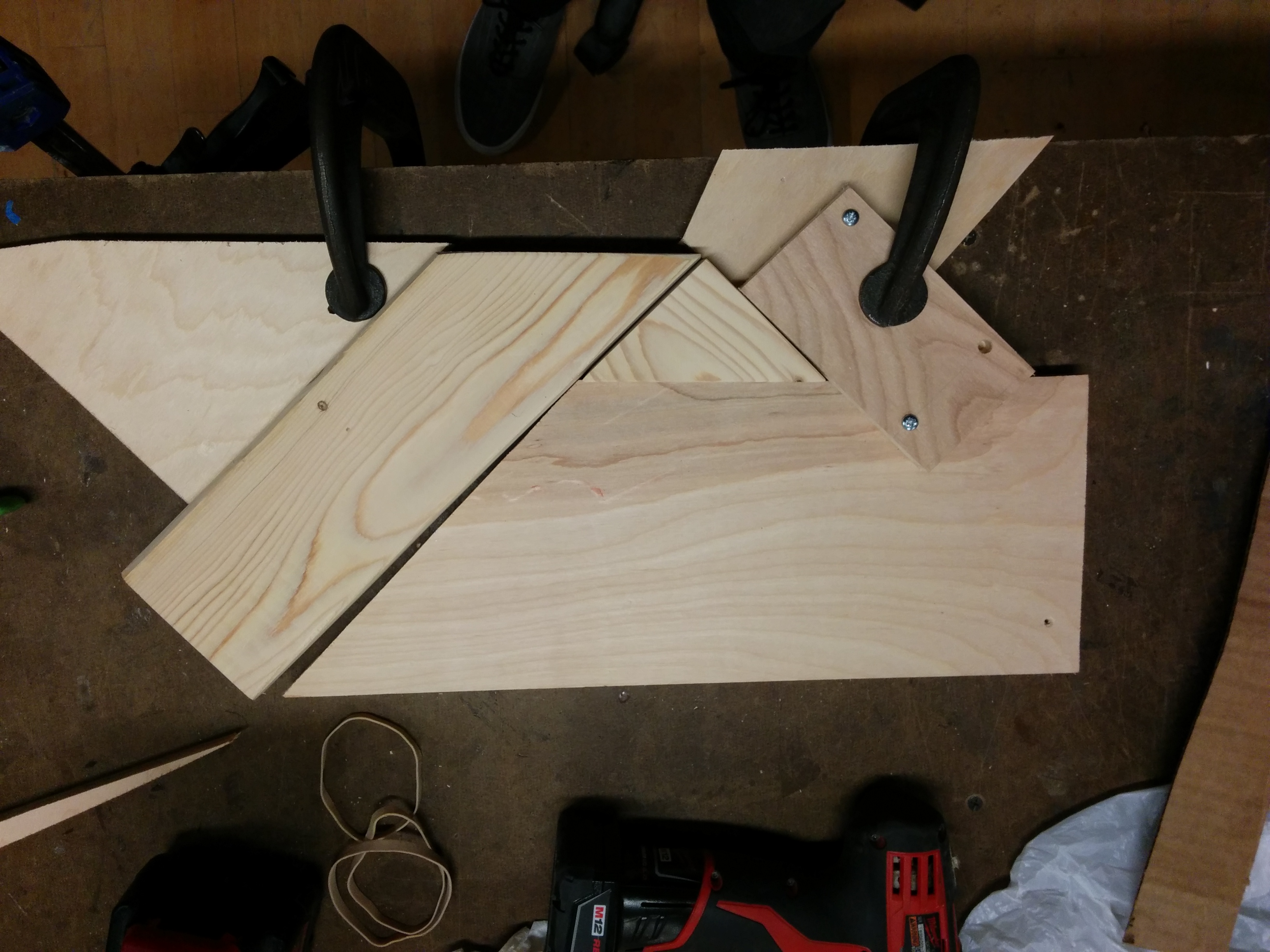
Making a jig
I was trying to find a good way to position my pieces and keep them stable as I did my first drilling. This is where you can really see that each piece is certainly not “exactly” the same. This ain’t photoshop! No copy and paste here.
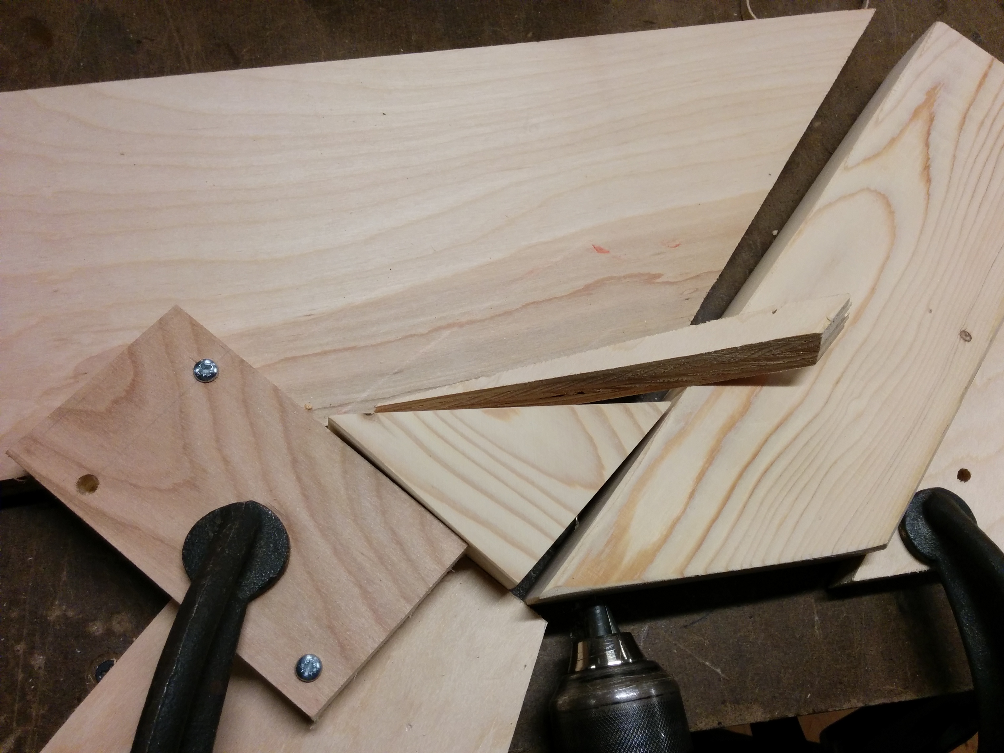
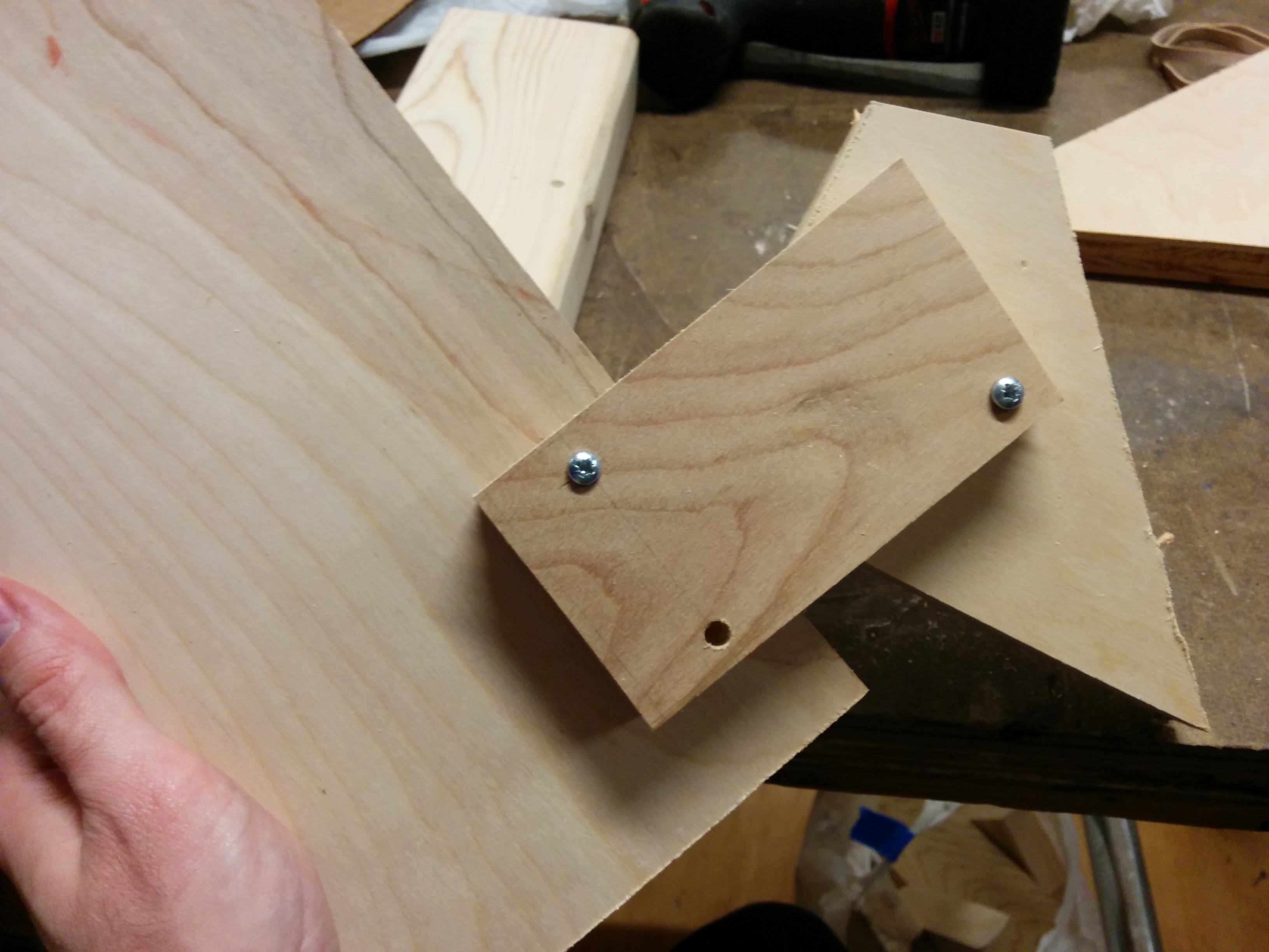
This made designing a good jig a little tough. I needed a tight fit, but thats hard to do when things aren’t exactly the same. Had to mess with it a bit… and then it failed on me. Turns out I wasn’t putting enough screws in it, and it started moving on it’s own. Not helpful, jig. I decided to re-think my approach.
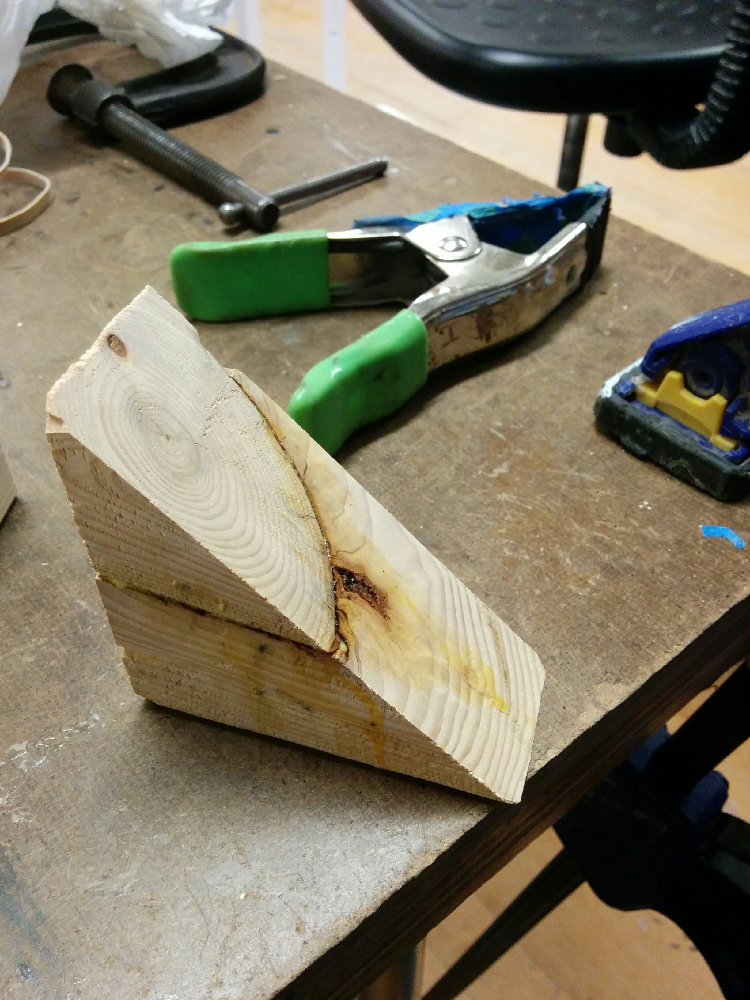
Back to the drawing board. I never lost faith in you, bad pancake. Your second life in service to the jig will never be forgotten.
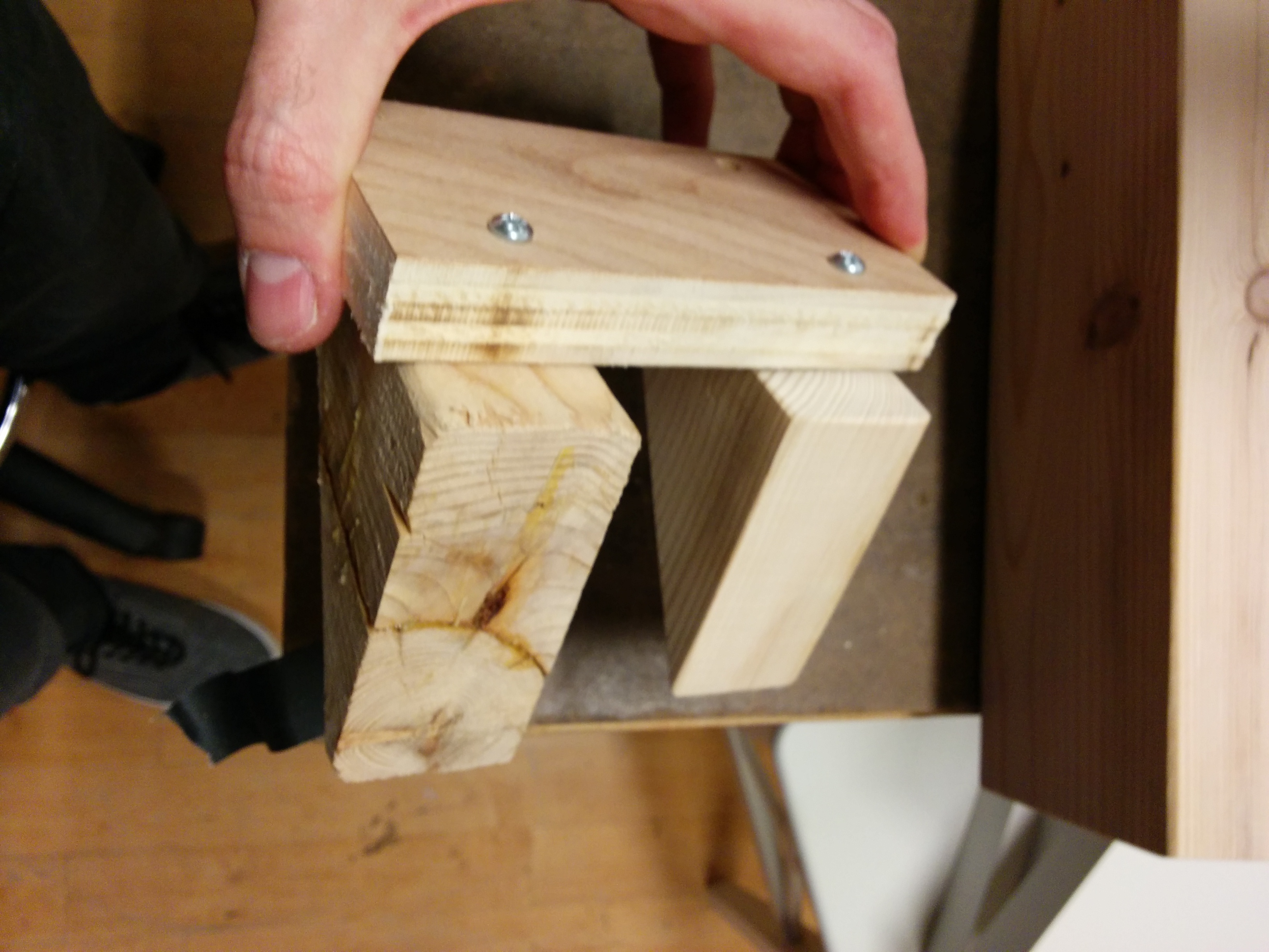
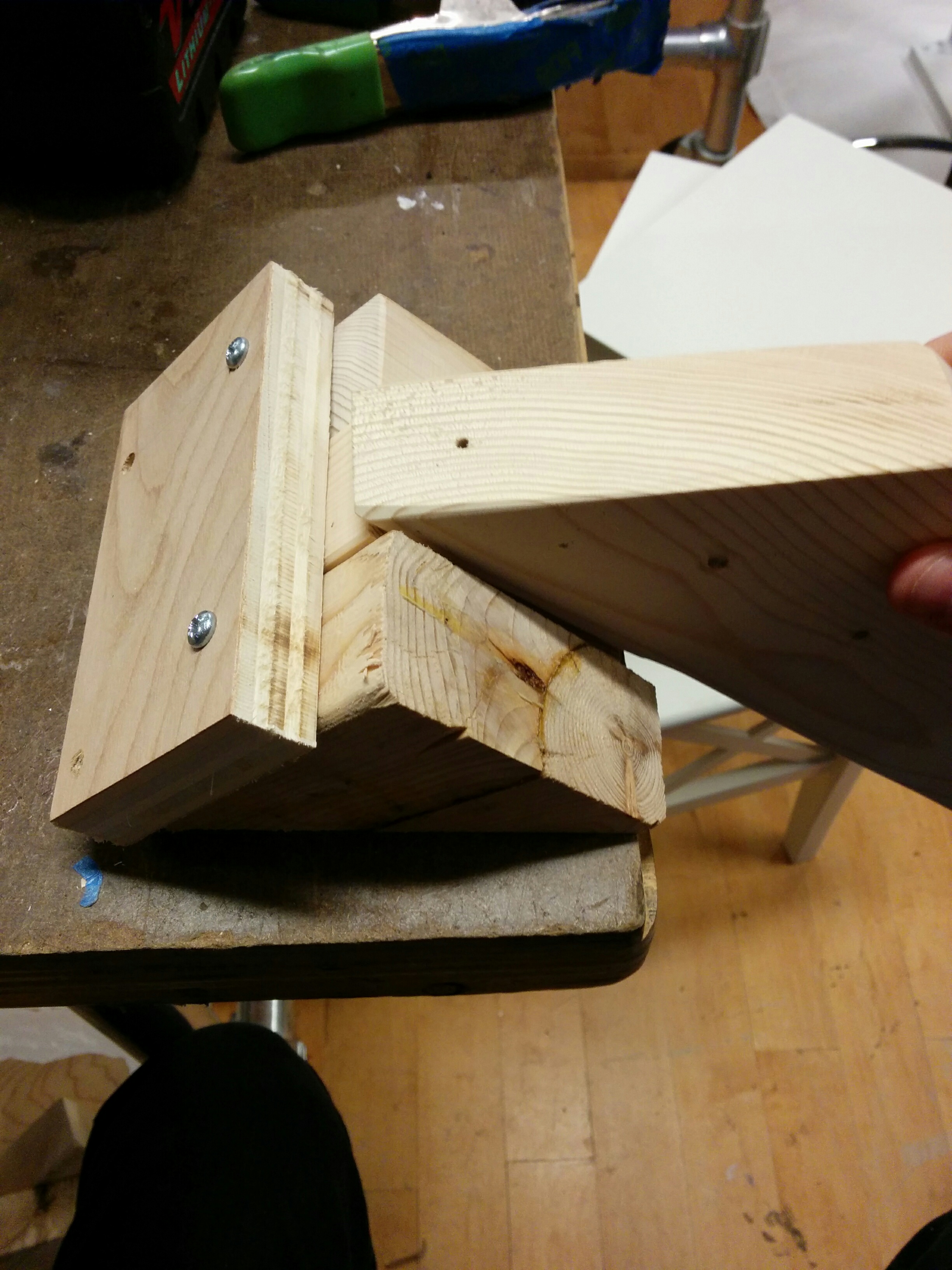
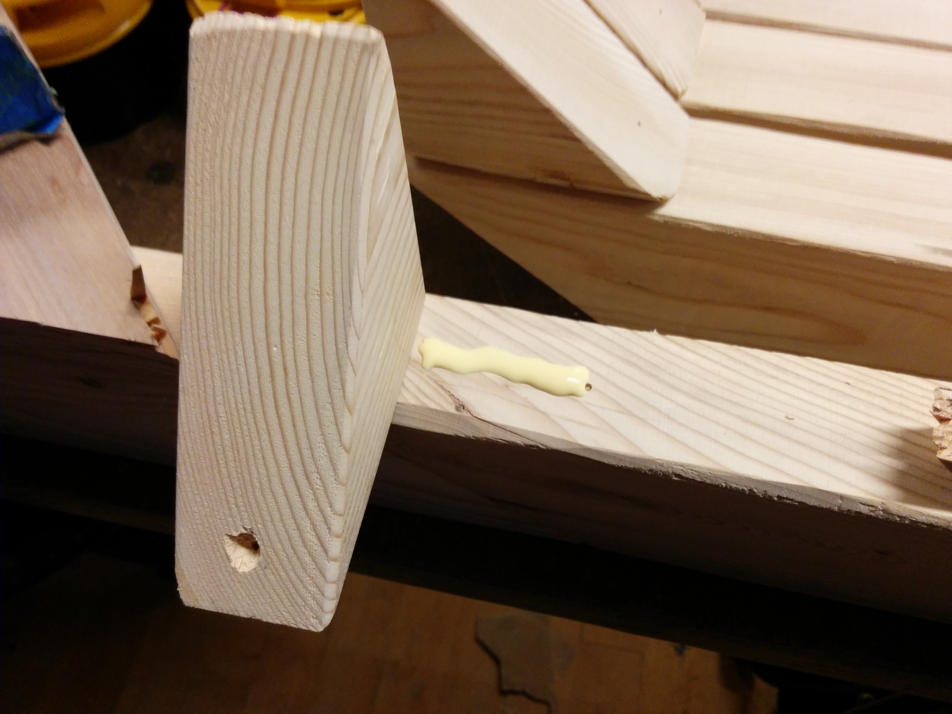
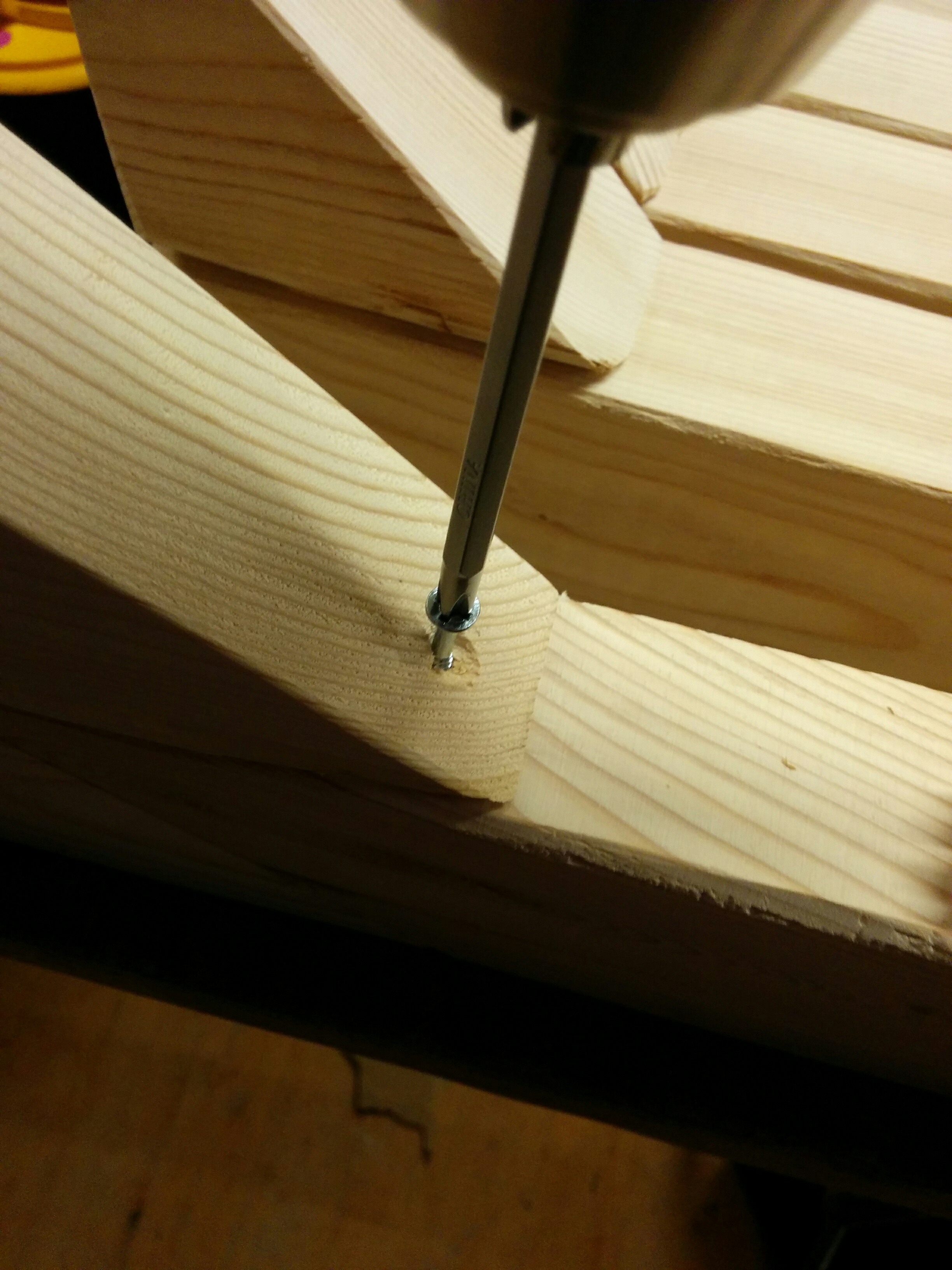
The first (full) pancake
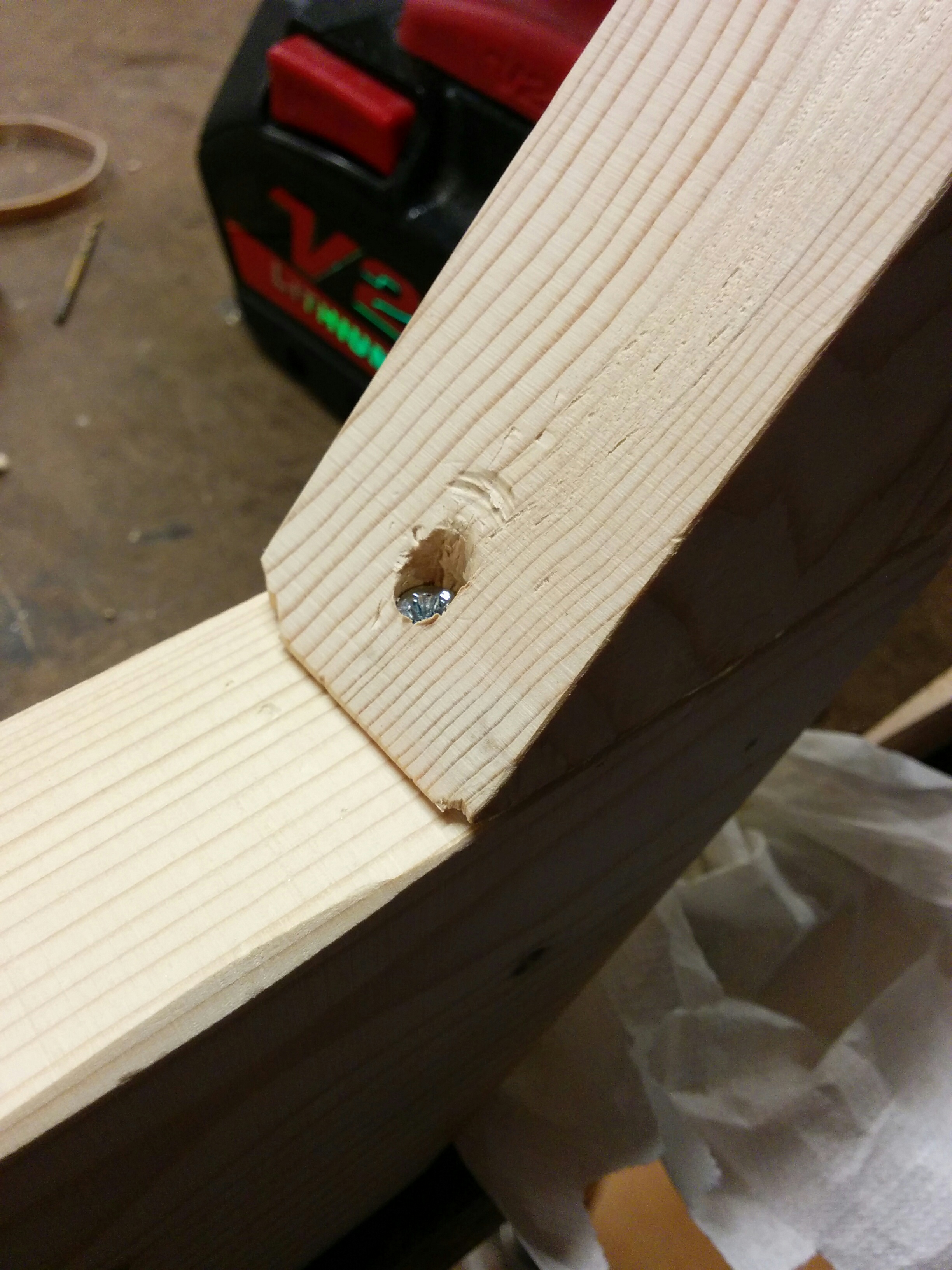
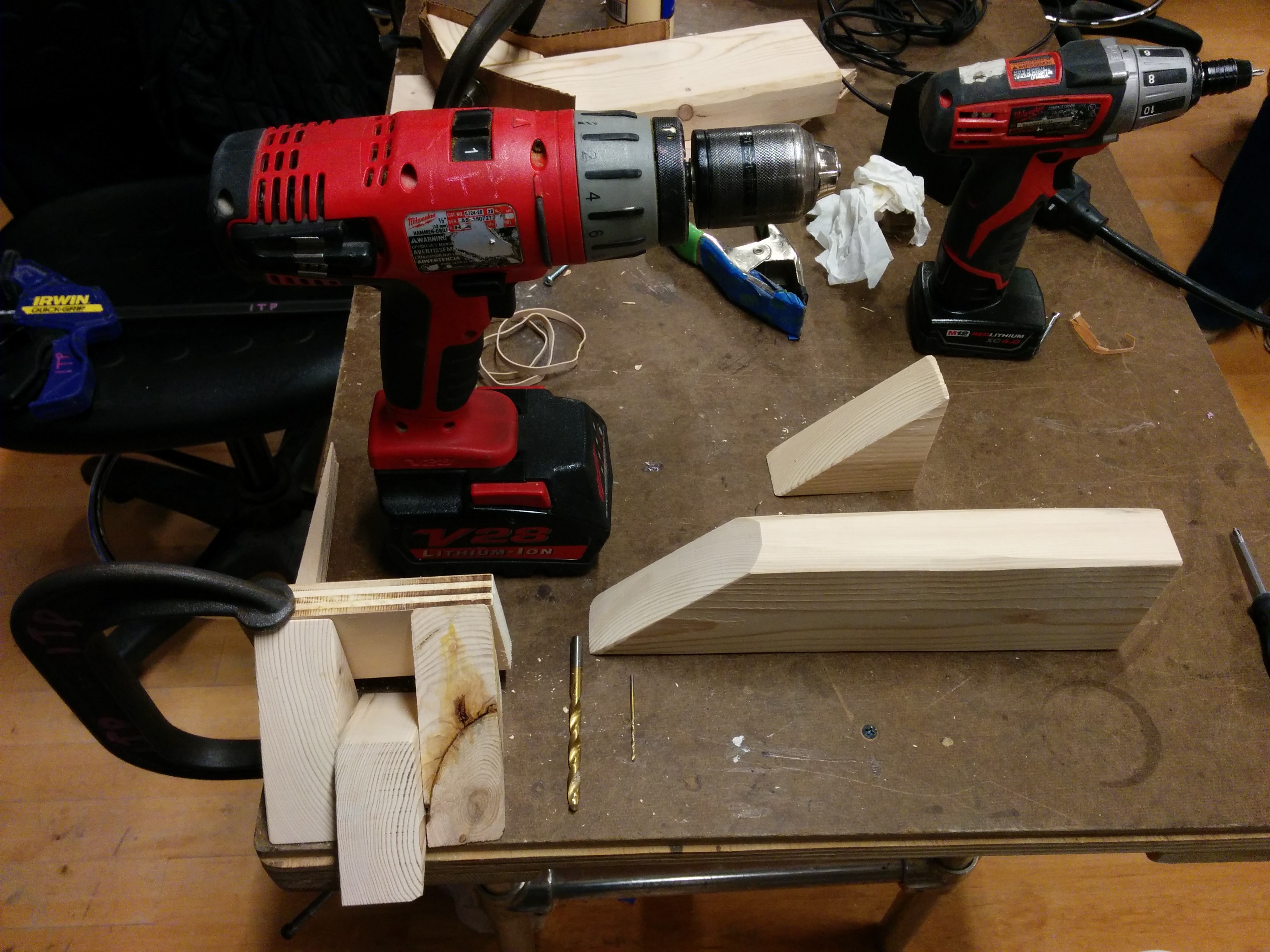
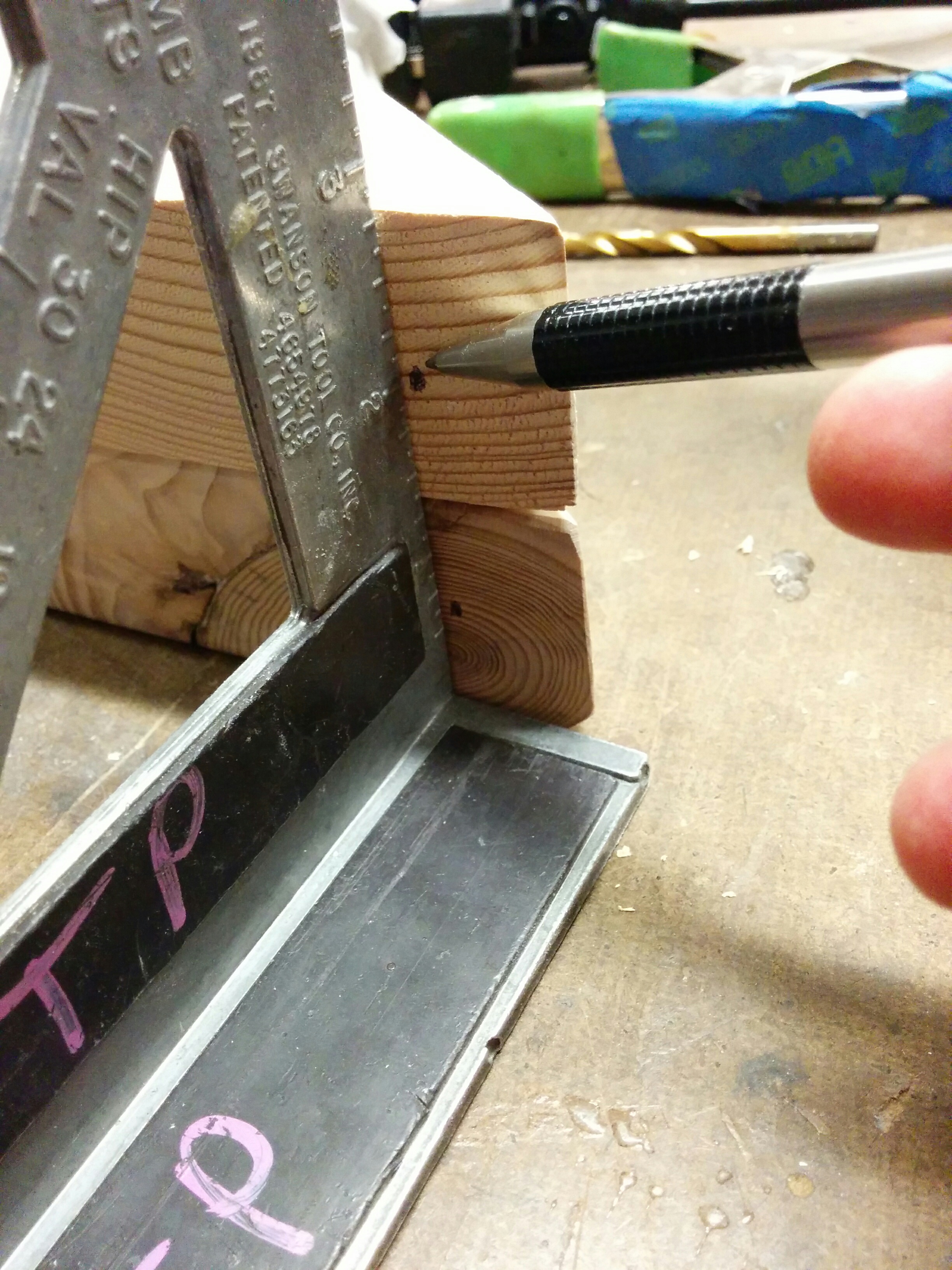
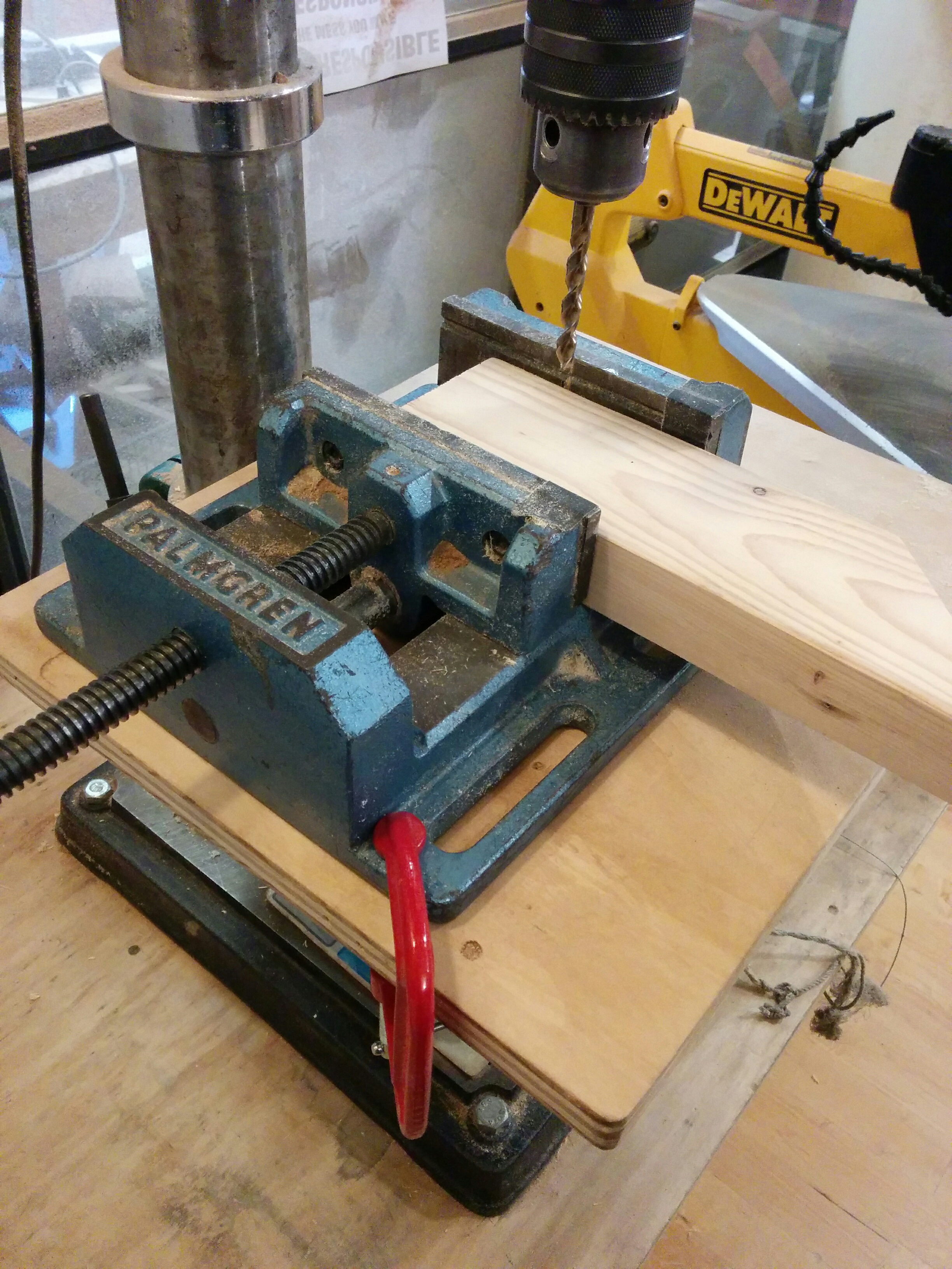
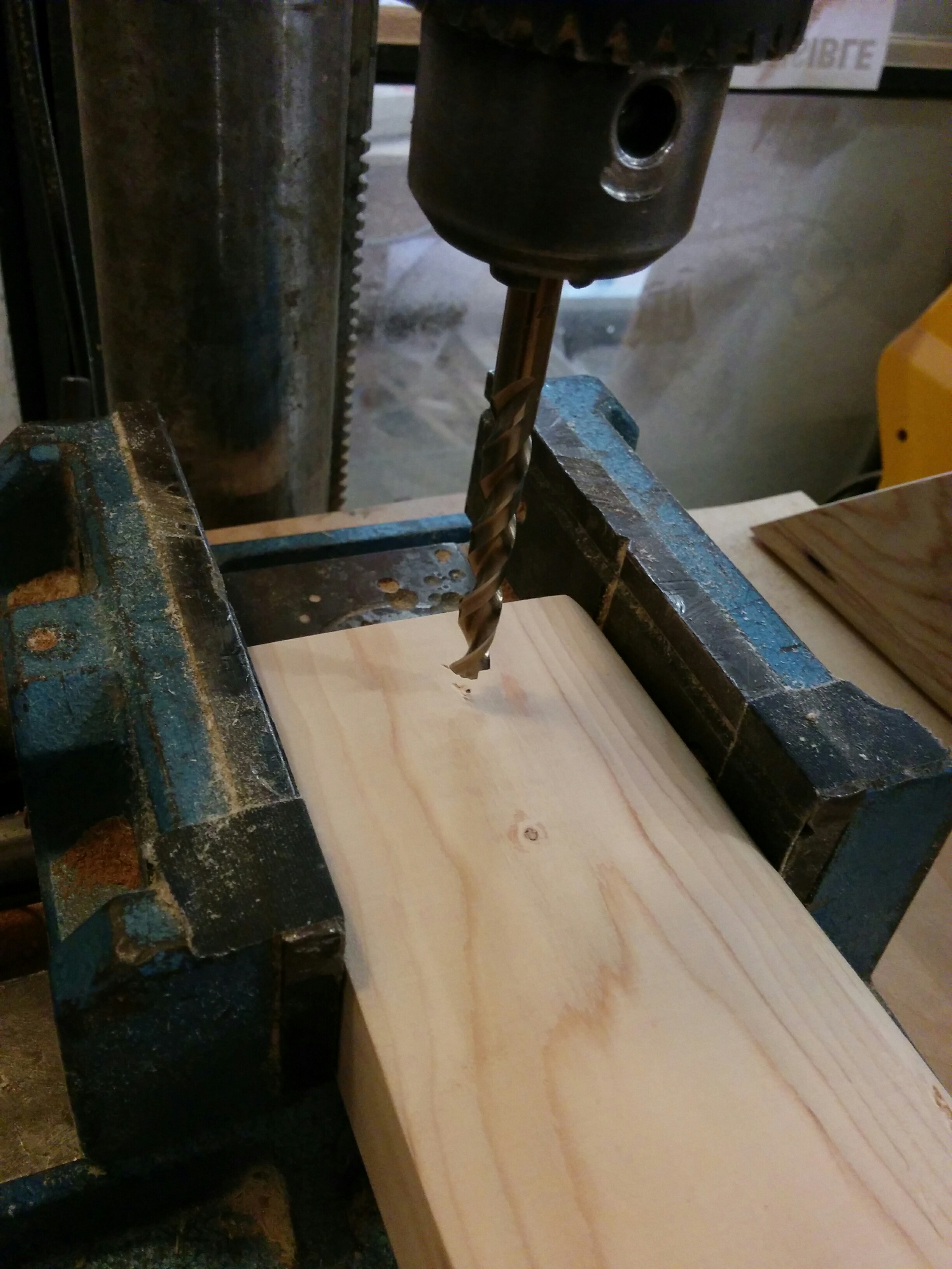
Before duplicating my process, I wanted to test it. I used one small drill bit as a pilot hole, then used a 1/4″ drill bit to just hit the top and allow for a screw head. Then I screwed that, moved the handle, applied glue between the handle and the body, and then did my drill and screw routine on the other side. Then clamp as the glue dried. (And slowly learning my lesson about using too much glue.)
Assembly line
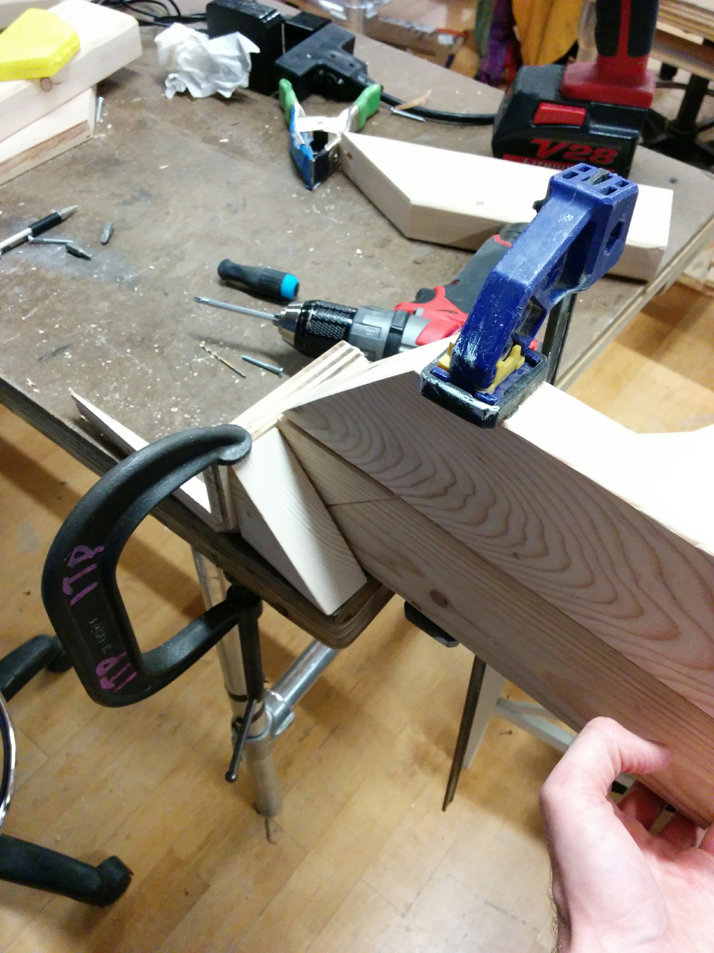
At the end I had a decent piece that felt sturdy in the hand. Then I started prepping everything for the assembly line. Marking out drill spots, arranging my clamps and double checking the workflow.
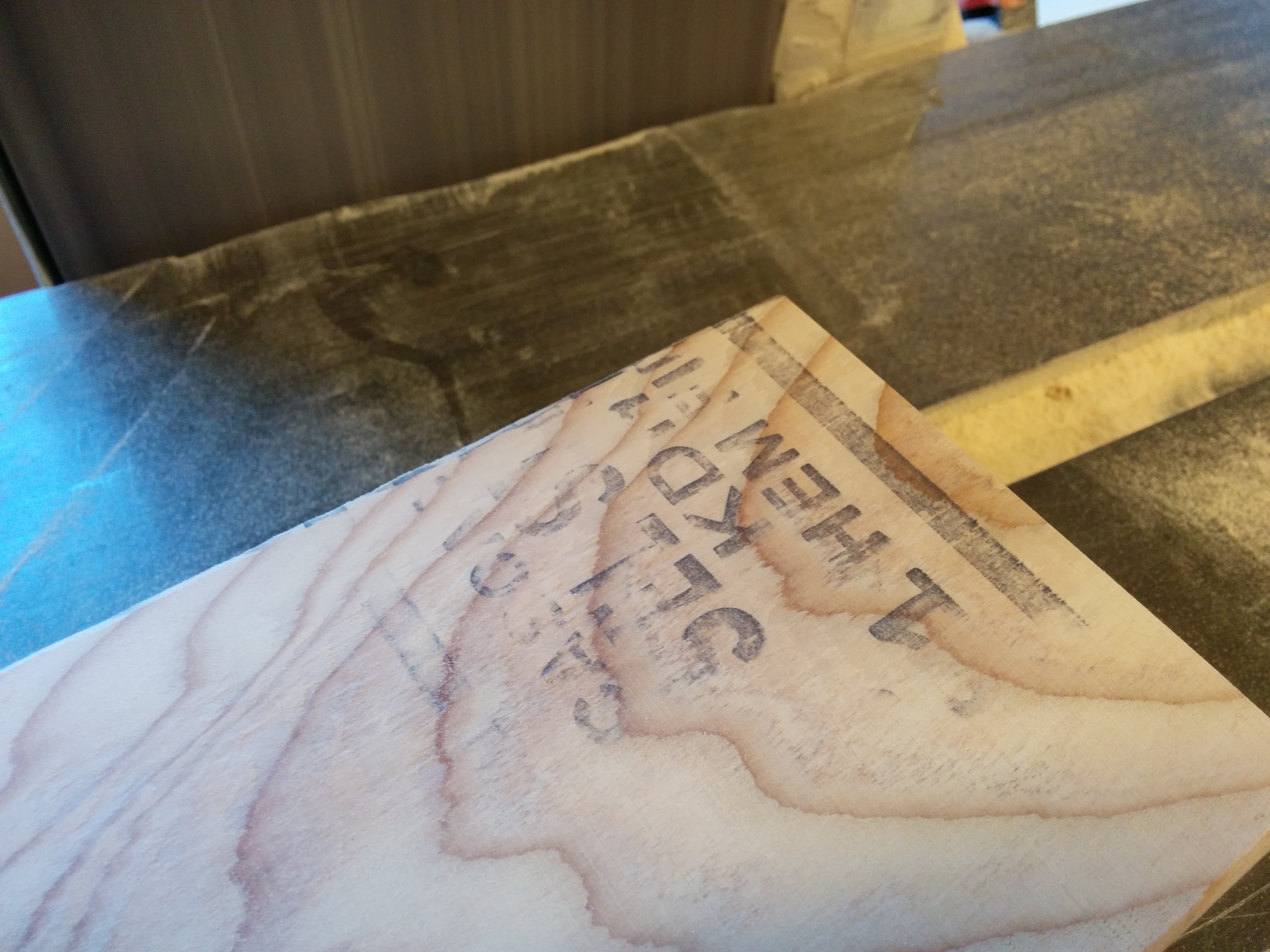
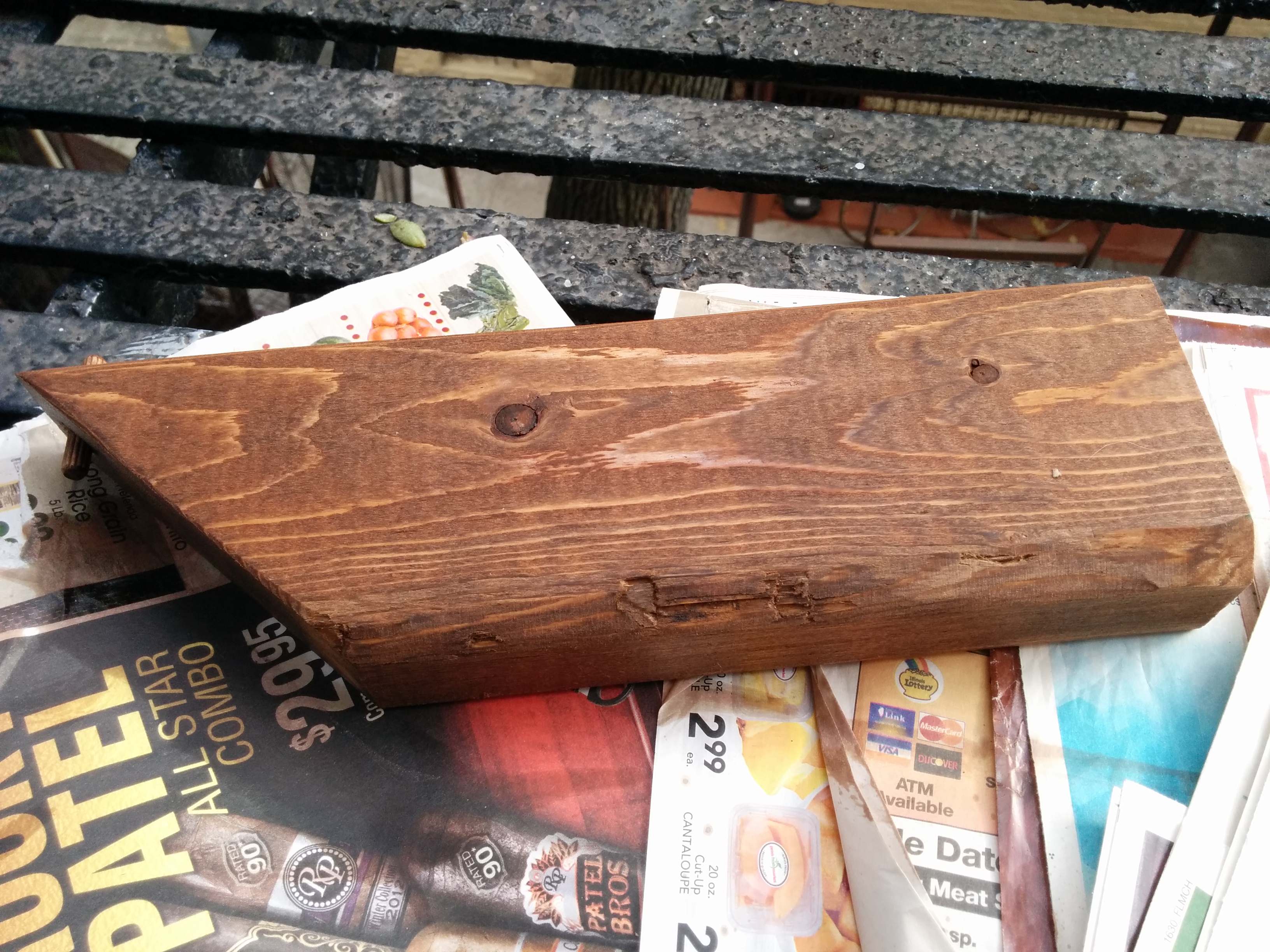
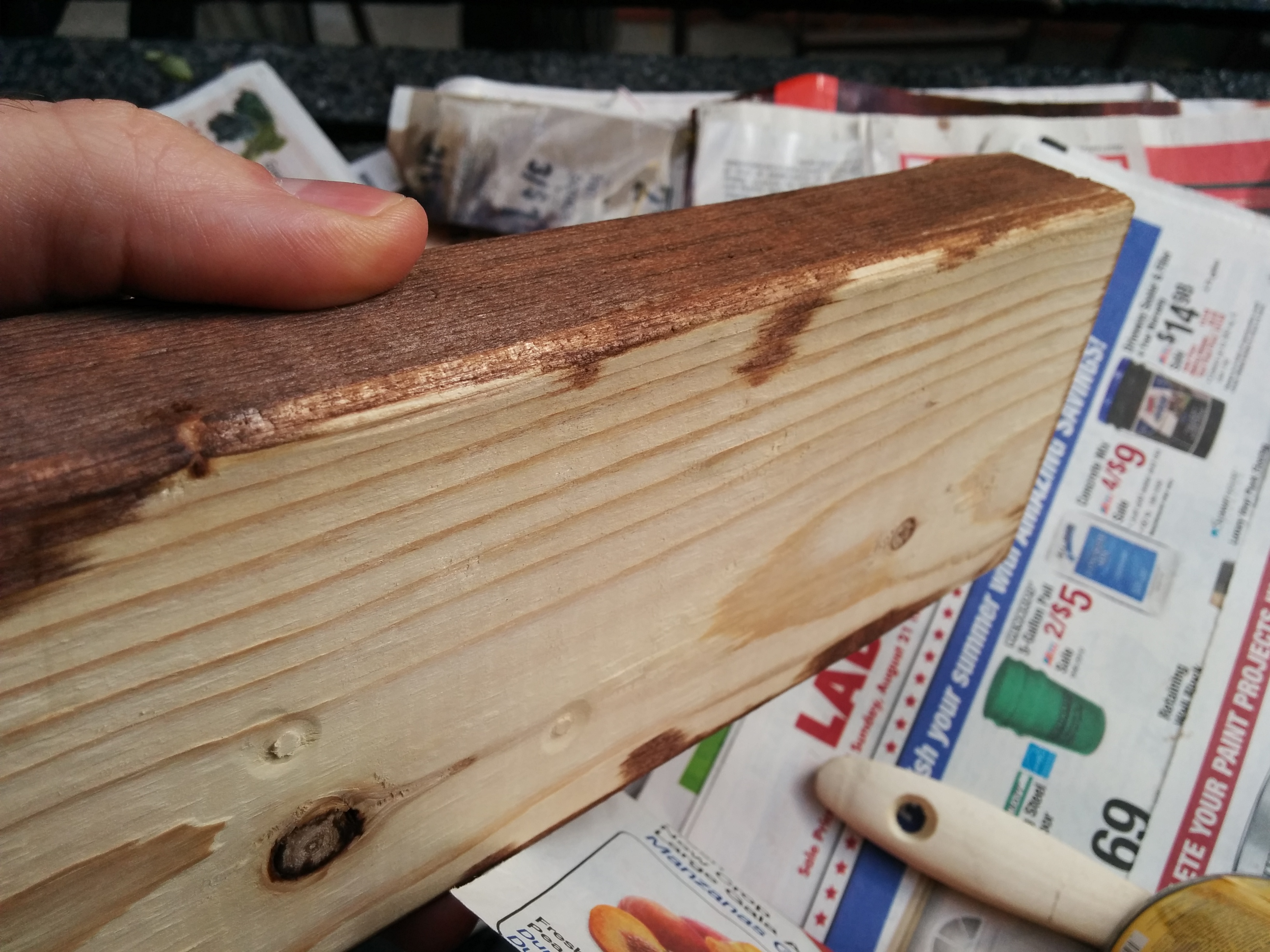
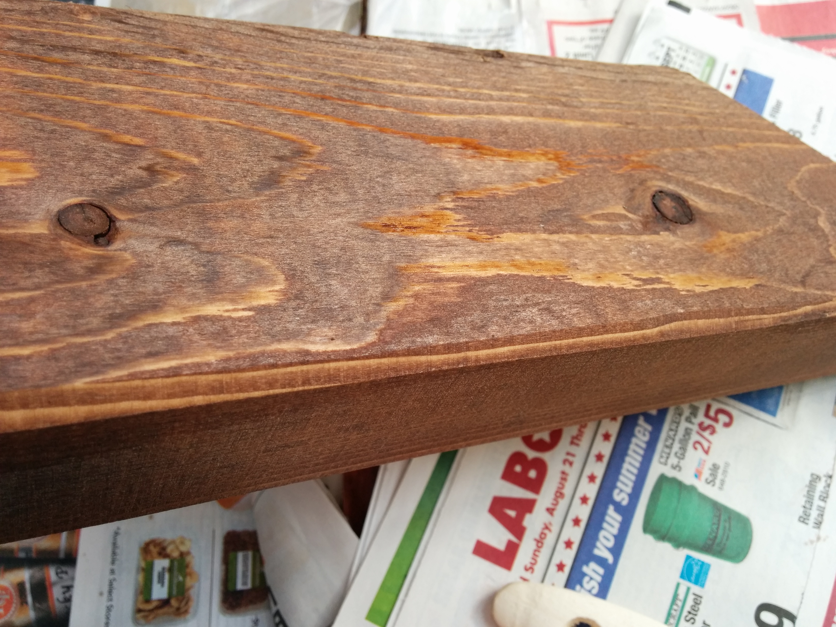
Stain?
I brief intermission followed as I had to go home for the day. I took a piece of wood with me and tested some stain that I bought, since we aren’t allowed to use stain in the shop. After an overnight drying, it was interesting to see the results. I kind of liked the color, but I feel like it would do well with a waxing. Ultimately, with some other issues outstanding (more on this later), I decided to go against staining. If I needed to make changes and alterations, it would just mess up my stain job, I’d need to re-apply, and make things even more messy and complicated. Interested in using it in the future, though.
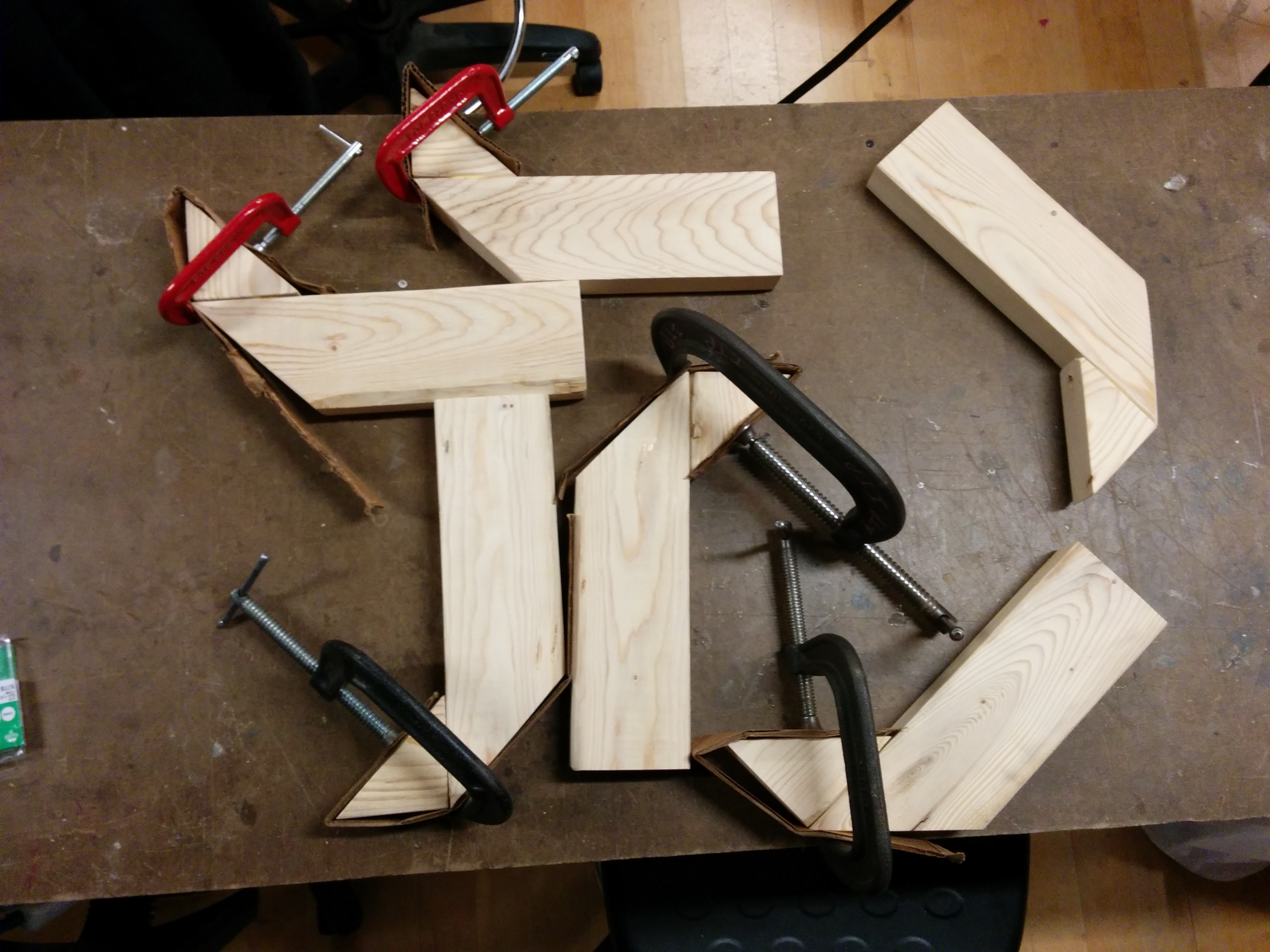
Glue n’ Screw
With that tangent aside, I set up the workflow for the rest of the pieces. Going to the shop when no one is there is *very* useful, as you can take as many drills as you want. I laid them out in order: pilot drill, space drill, glue, screw.
I even made a little makeshift shelf for my small clamp so it would be elevated and within arms reach.
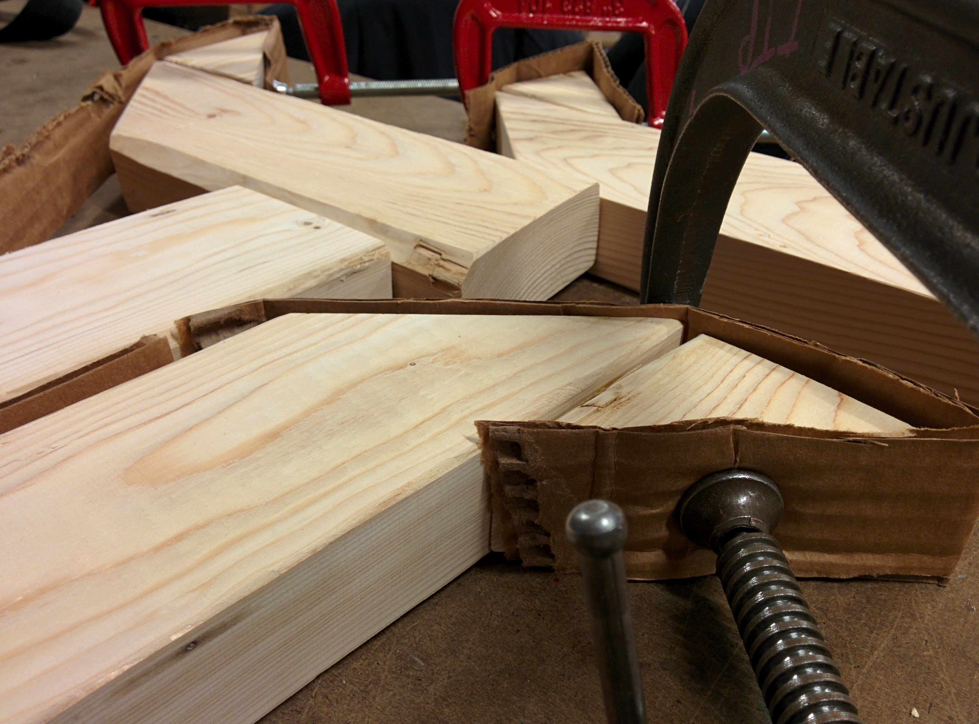
Then I used cardboard to protect all the pieces and clamped them up for a while.
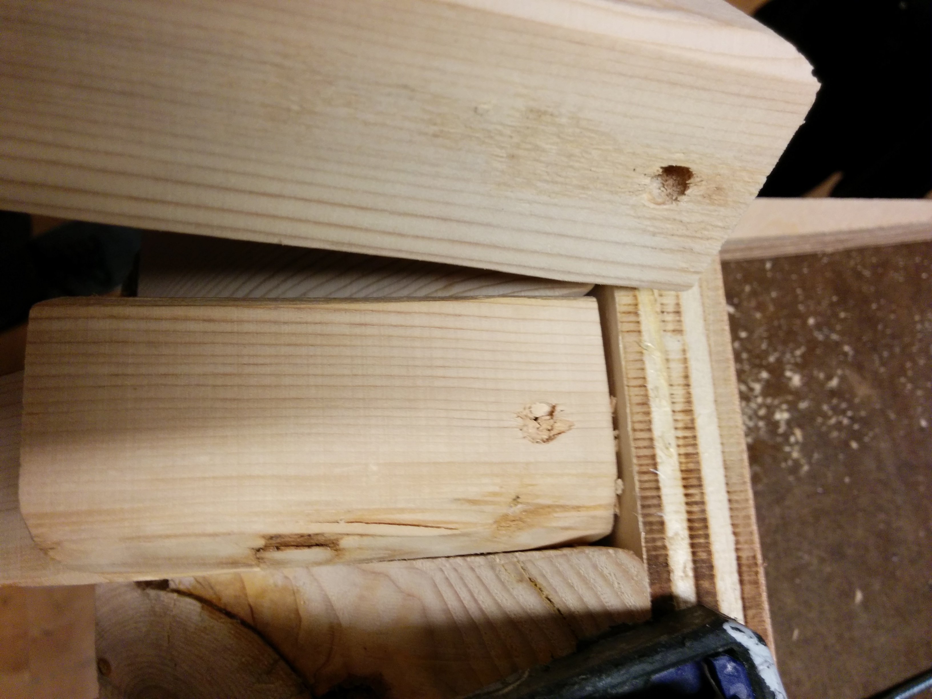
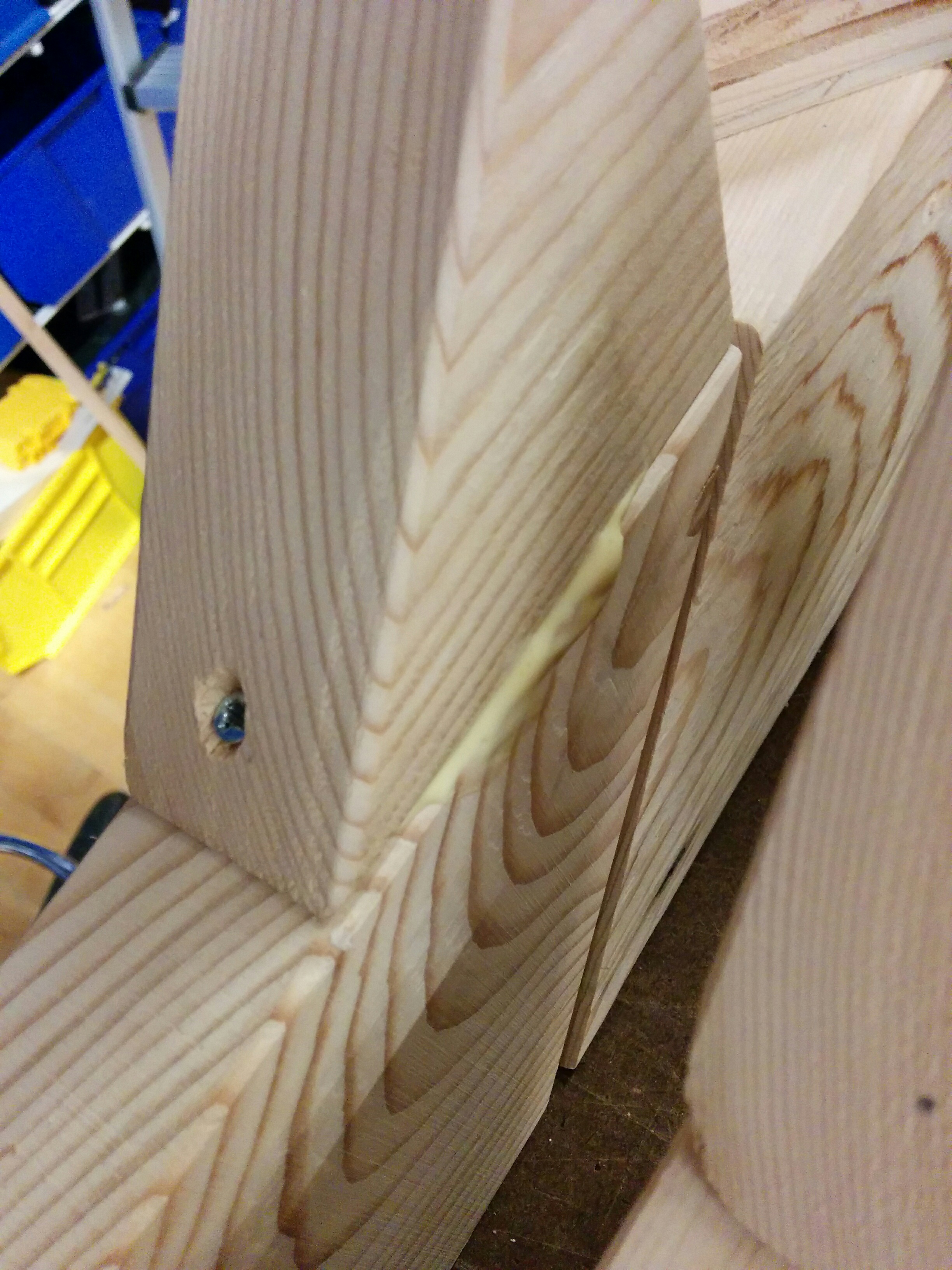
Sand again
I can almost hear Ben’s laughter now. None of these were “exactly” the same at all. Handles weren’t perfectly lined up, and gaps between the handles and the wand were visible and varied from piece to piece. This didn’t interfere with the base function, however. I decided to sand them down to make them as flat and uniform as possible, and additionally soften sharp edges that would be gripped by hands.
The heartbreak
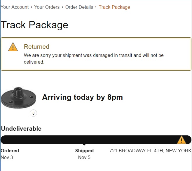
Why Amazon? Why? Whyyyyyyyy? One of my sets of components had been damaged in transit and was being re-sent… for delivery on Wednesday. Additionally, there were some issues with delivery of the other pieces. I now know more about the ITP, NYU and USPS mail system than any sane person needs to. But I was sweating a bit as well. This is what I was keeping in mind when I didn’t stain: if I had to change things around, I might need to make more cuts or change the design in order to get something done by Tuesday.
Time to improvise
As of this writing, I am waiting on a few other pieces of gear. Depending on when I get what I get, I’ll need to adjust my final project. Will I get my materials on time? Will I have to radically change my final design? Will Ana up front ever forgive me for pestering her incessantly about when packages are getting in? Find out next time in part two of… The Multiples!
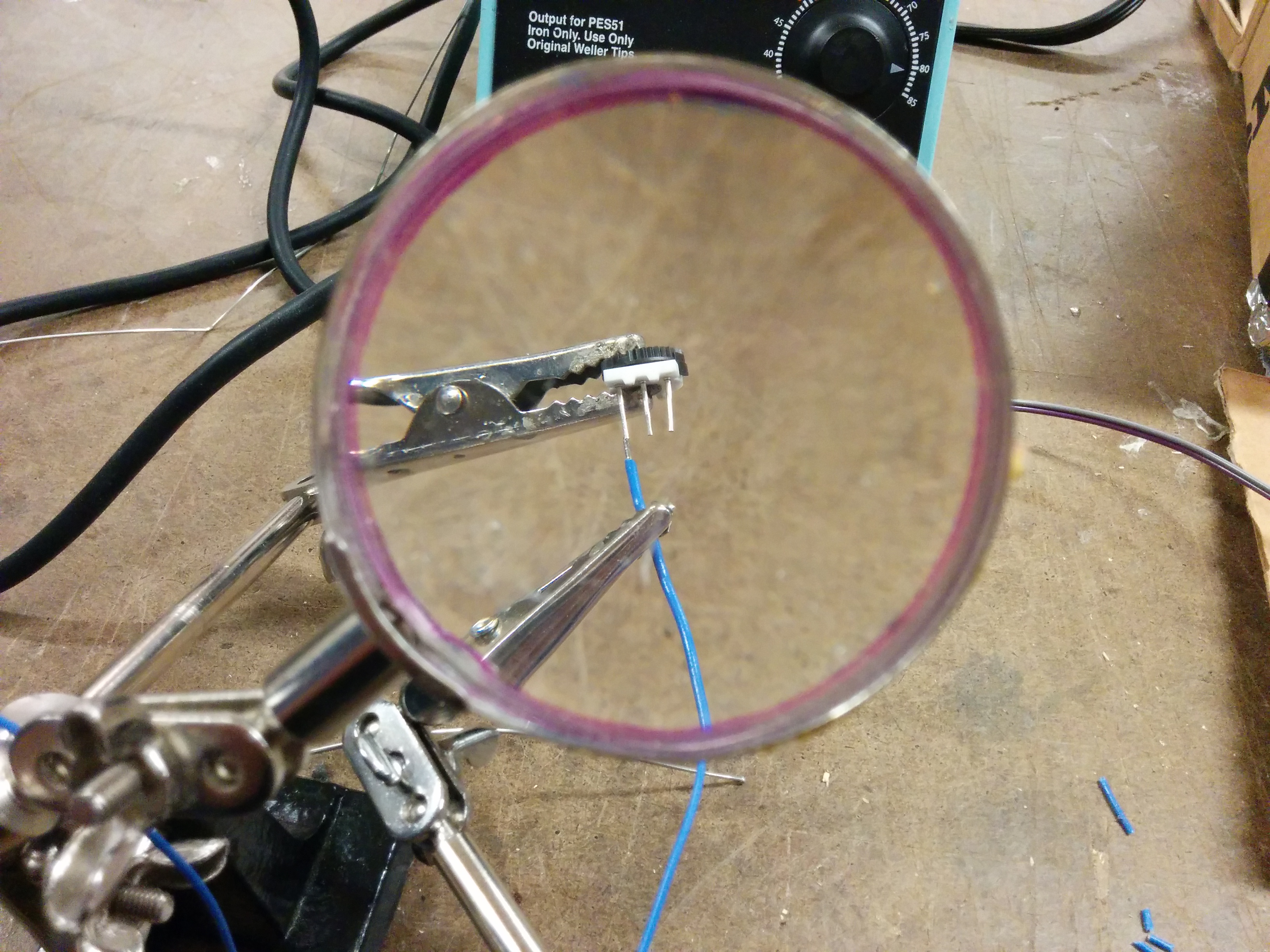
(During the intermission, I will solder the components that I *do* have)
Thank your shop staff: Dhruv
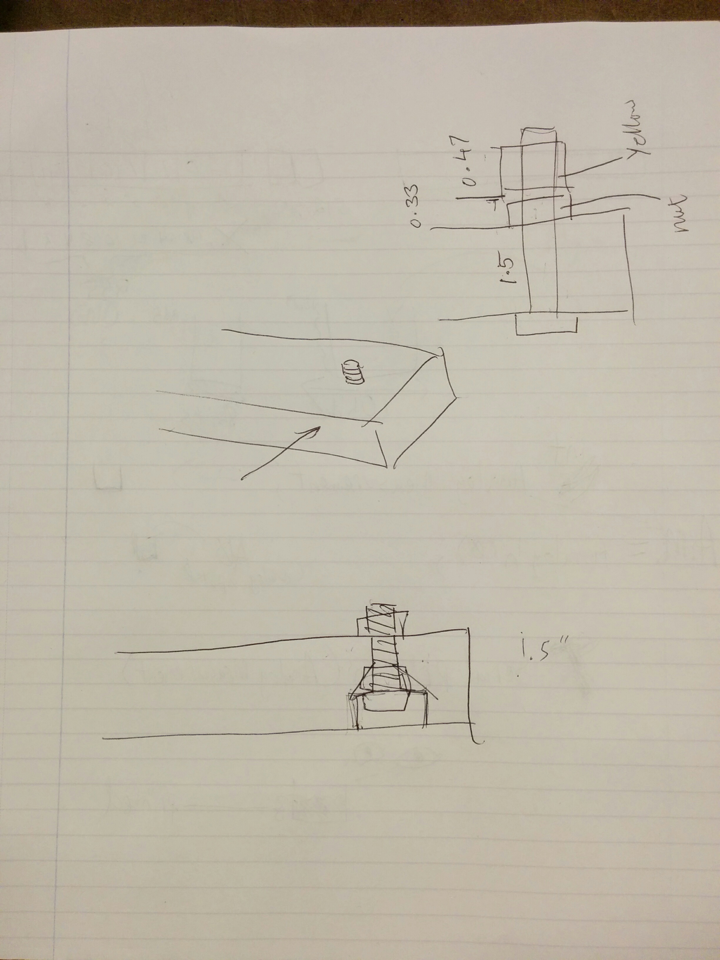
I have been blessed by the friendly shop staff! Dhruv helped me figure out an alternative mounting solution that would replace my broken/missing delivery.
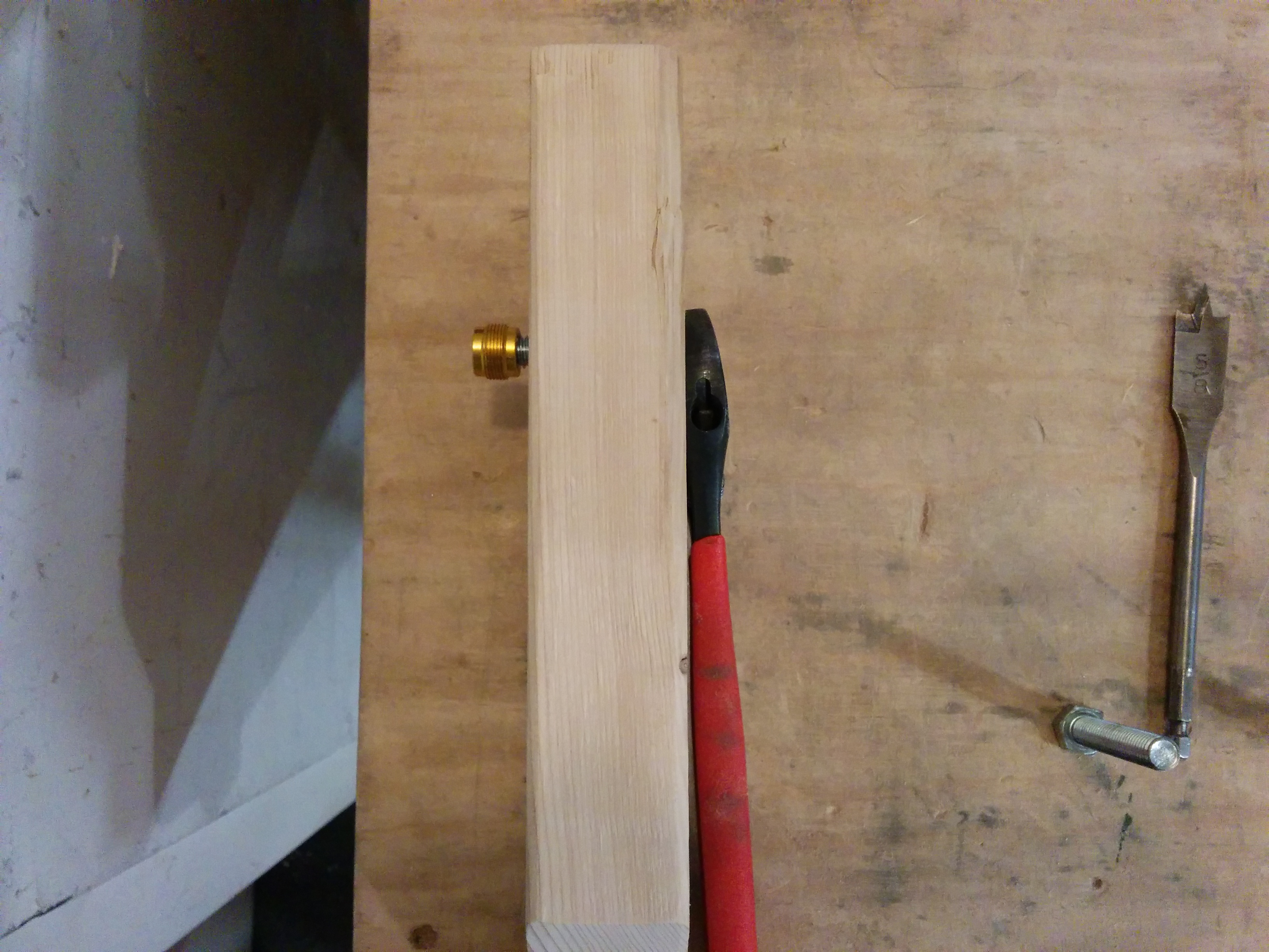
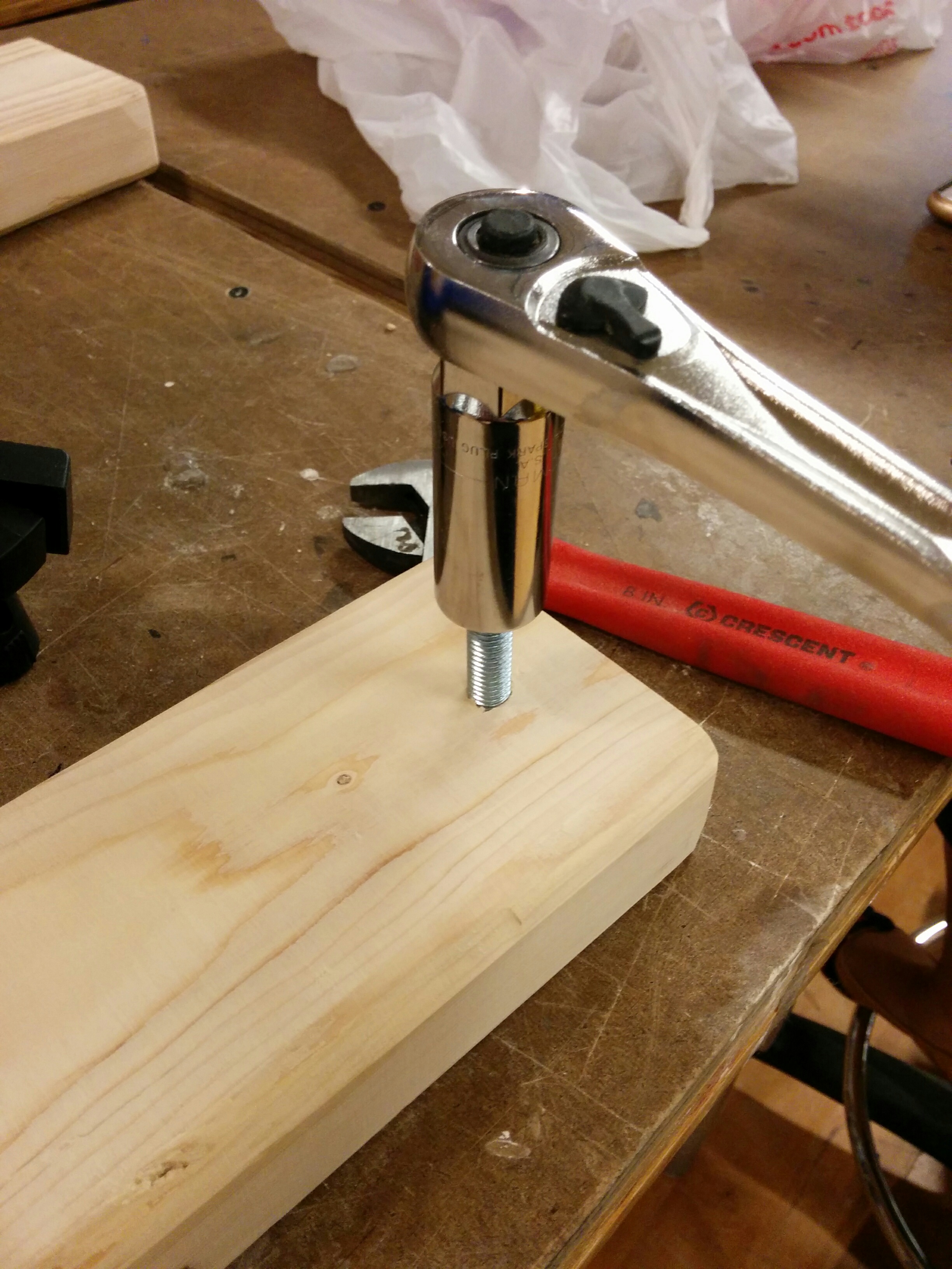
Essentially, we found a threaded bolt that was the perfect size for the clips that I have. Dhruv helped me get the right drill bit, and I went at testing the theory.
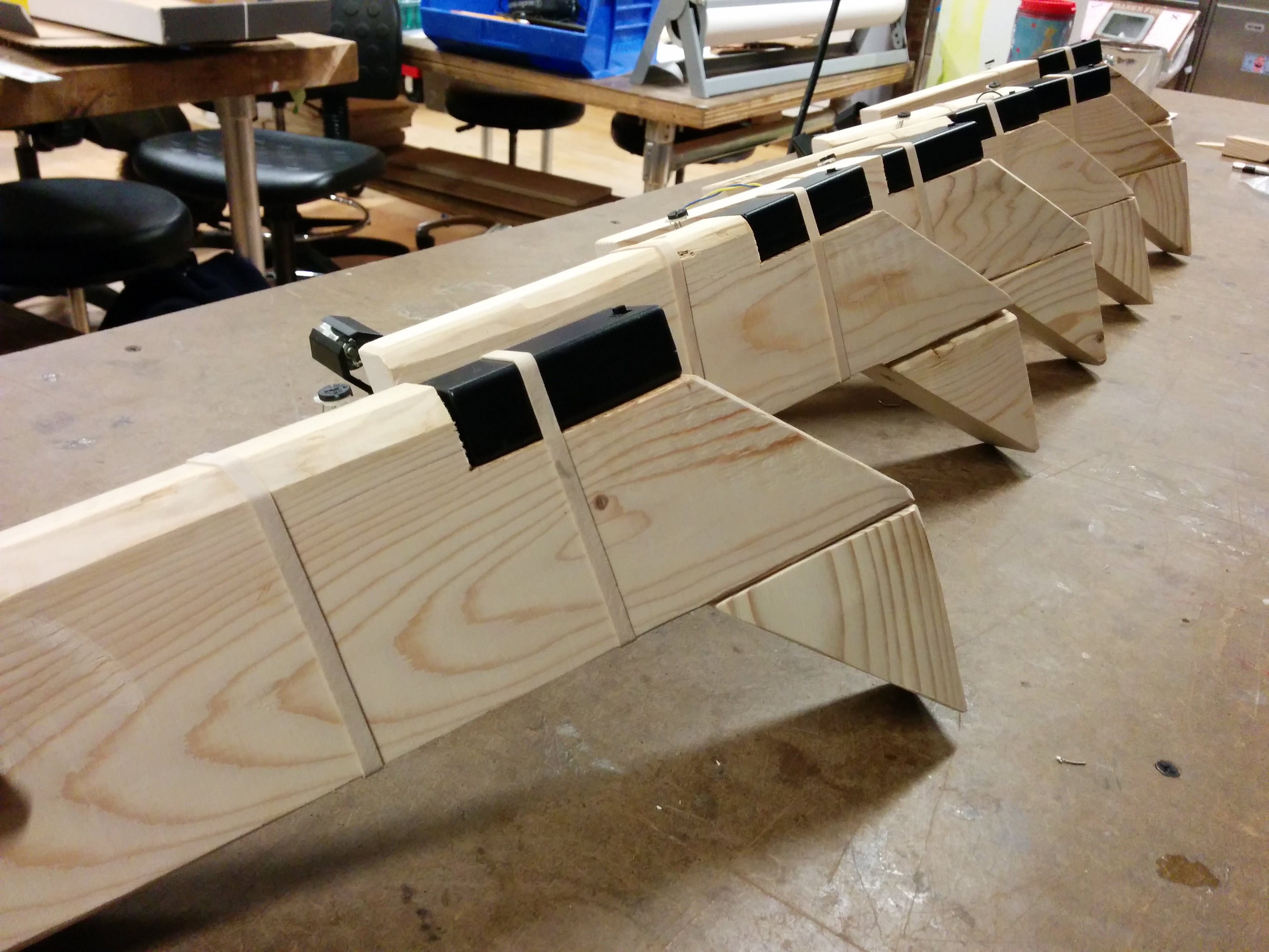
Yes! After the proof of concept, I was ready to continue. First marking, then drilling, and of course going back to the sander yet once again.
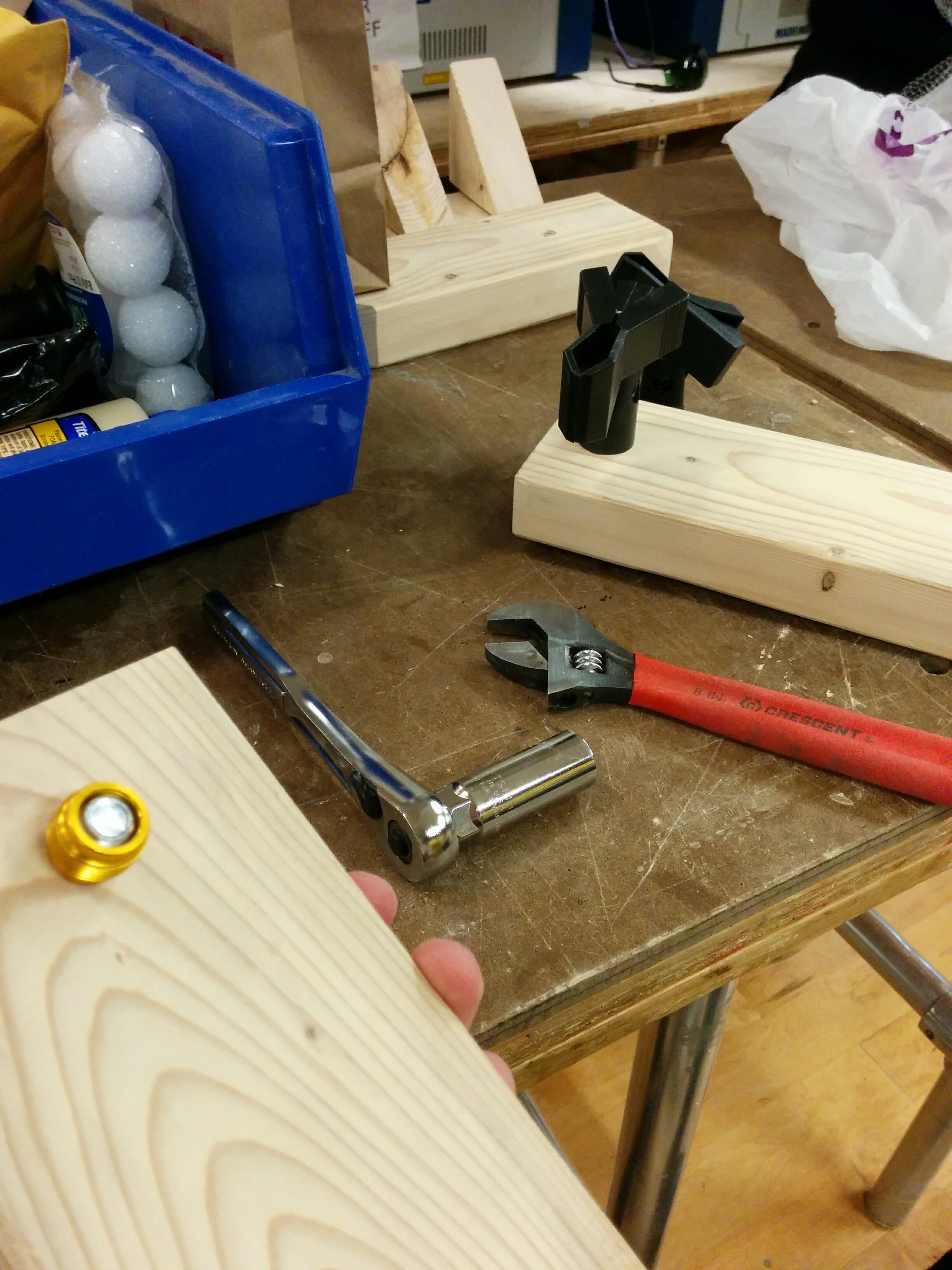
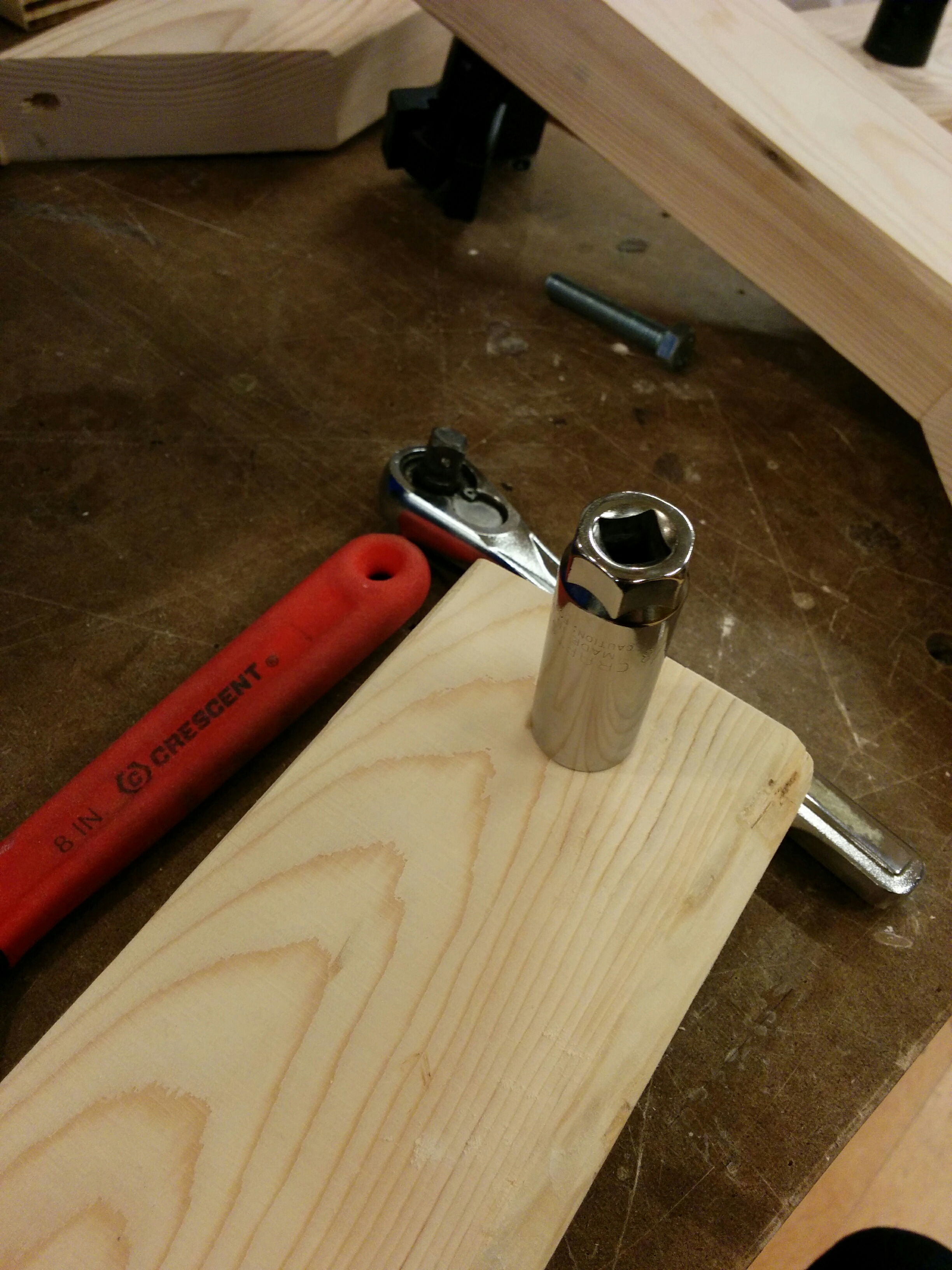
I found the right tool for the job (ratchet, and then wrench for more delicate scenarios). Then, I laid out everything again to do my assembly line round 2.
Not without a brief heart attack thinking that I had permanently attached a ratchet head to one of my pieces. (It was really… really stuck on there.)
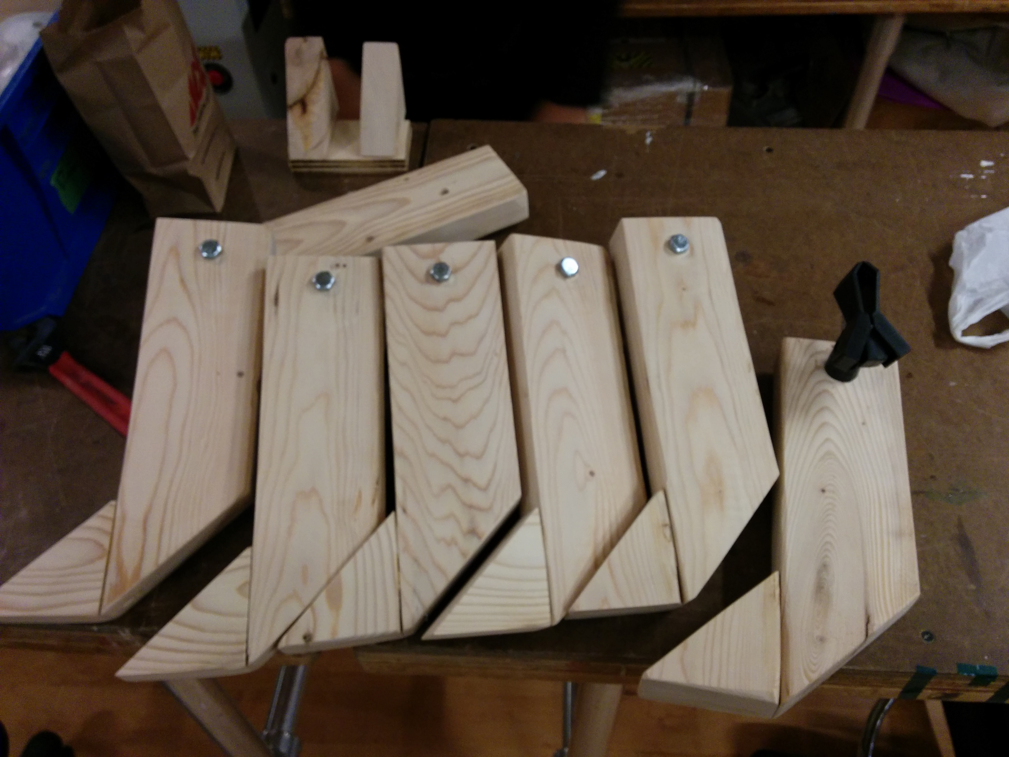
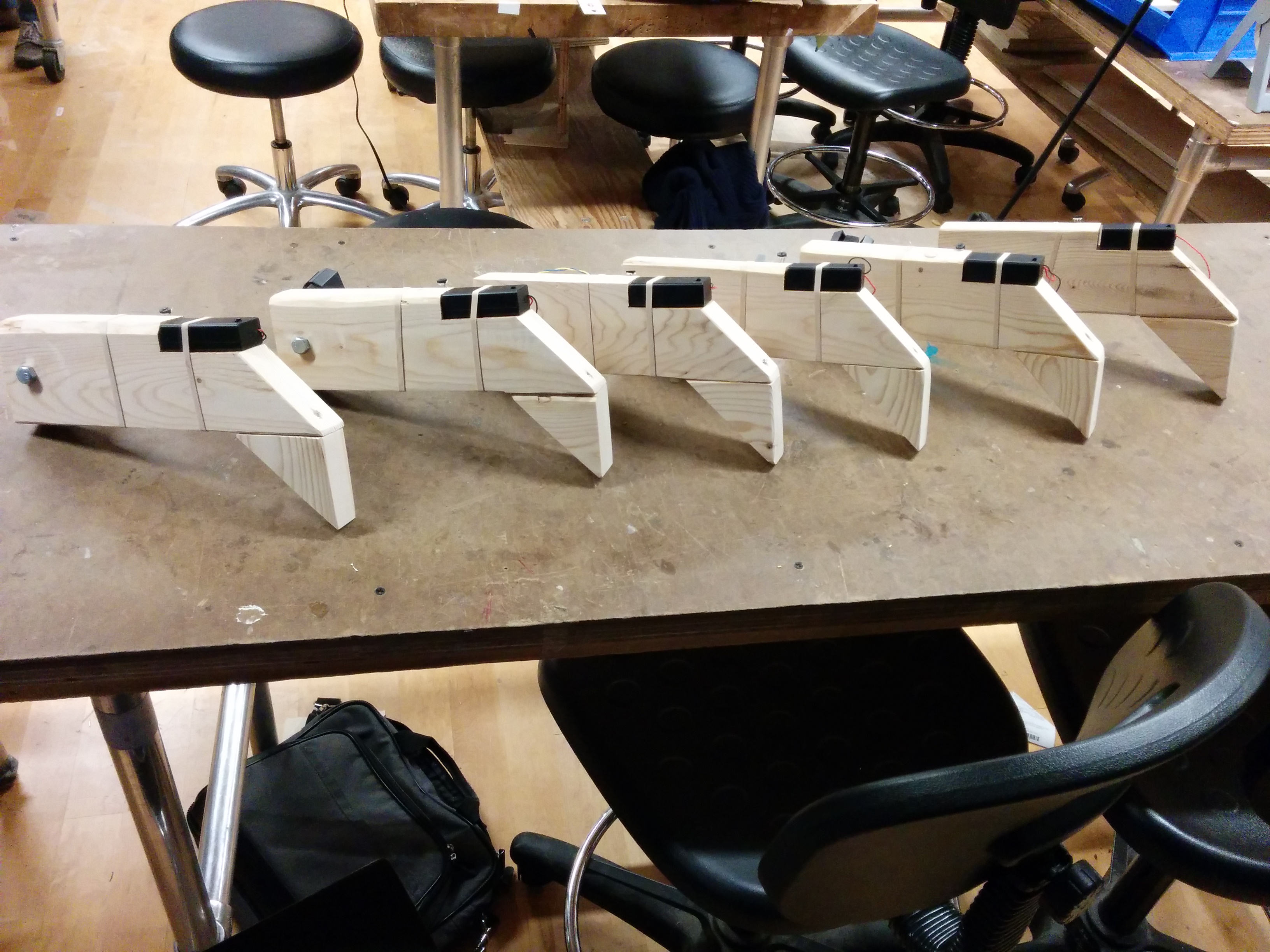
And I got it working! Except…♫one of these things is not like the other, one of these things does not belong♫
(Yes, it annoyed me enough that I fixed it. Luckily my design made it simple to unscrew and re-screw everything back together the right way).
As of this writing, I had gotten this far but still hadn’t received my packages yet. Desperate, defeated, and considering an expensive run to Tinkersphere. But just when I was getting ready to give up, I received a call… from the Campus Mail Services!
I’m not sure I will be able to post everything completed before 6pm tonight, so I wanted to get this blogged least to show how much I have gotten so far. I’m confident I will finish tonight and have something to show tomorrow morning. Updates to follow, stay tuned!
And now, for the thrilling conclusion of… The Multiples!
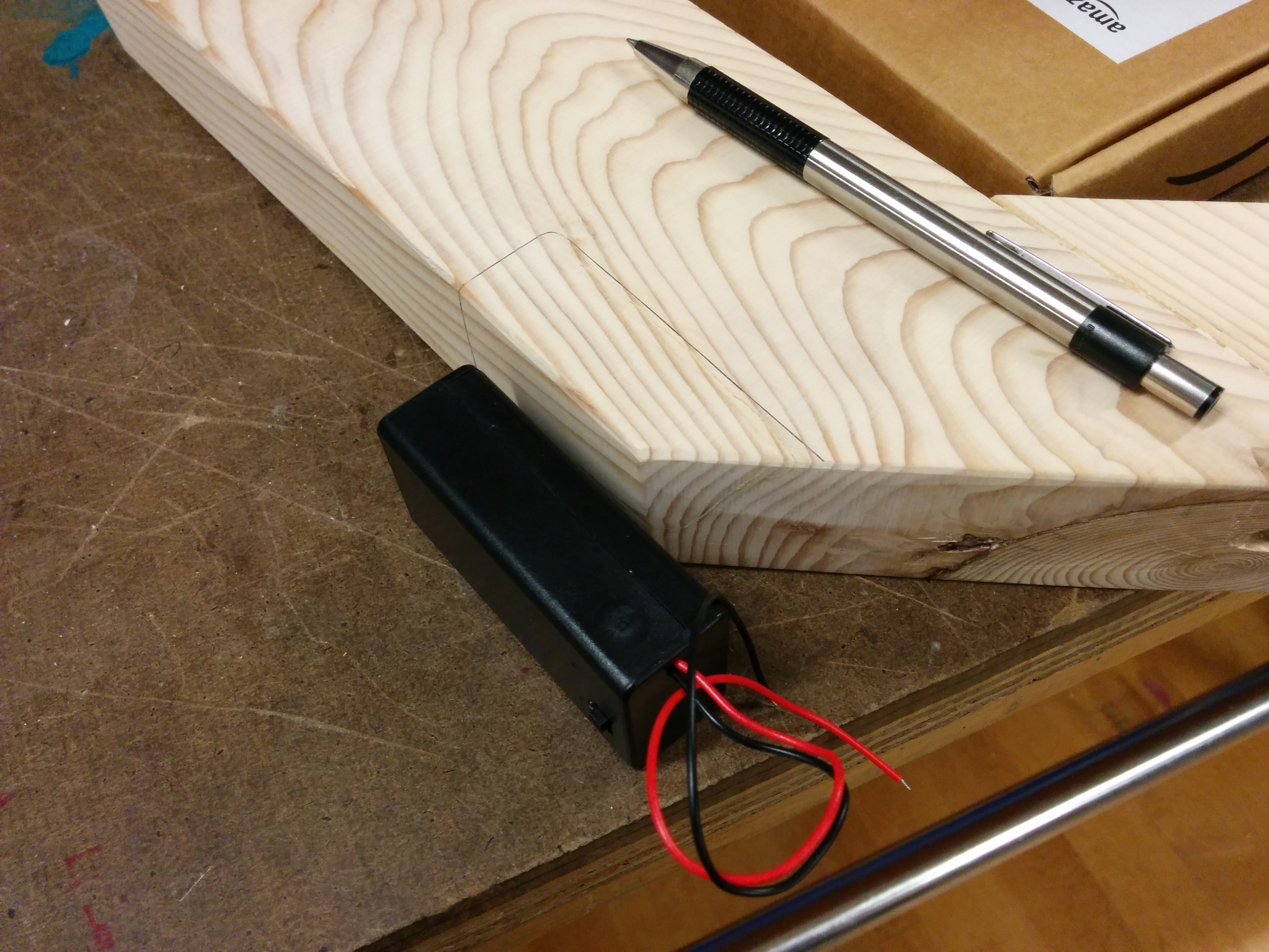
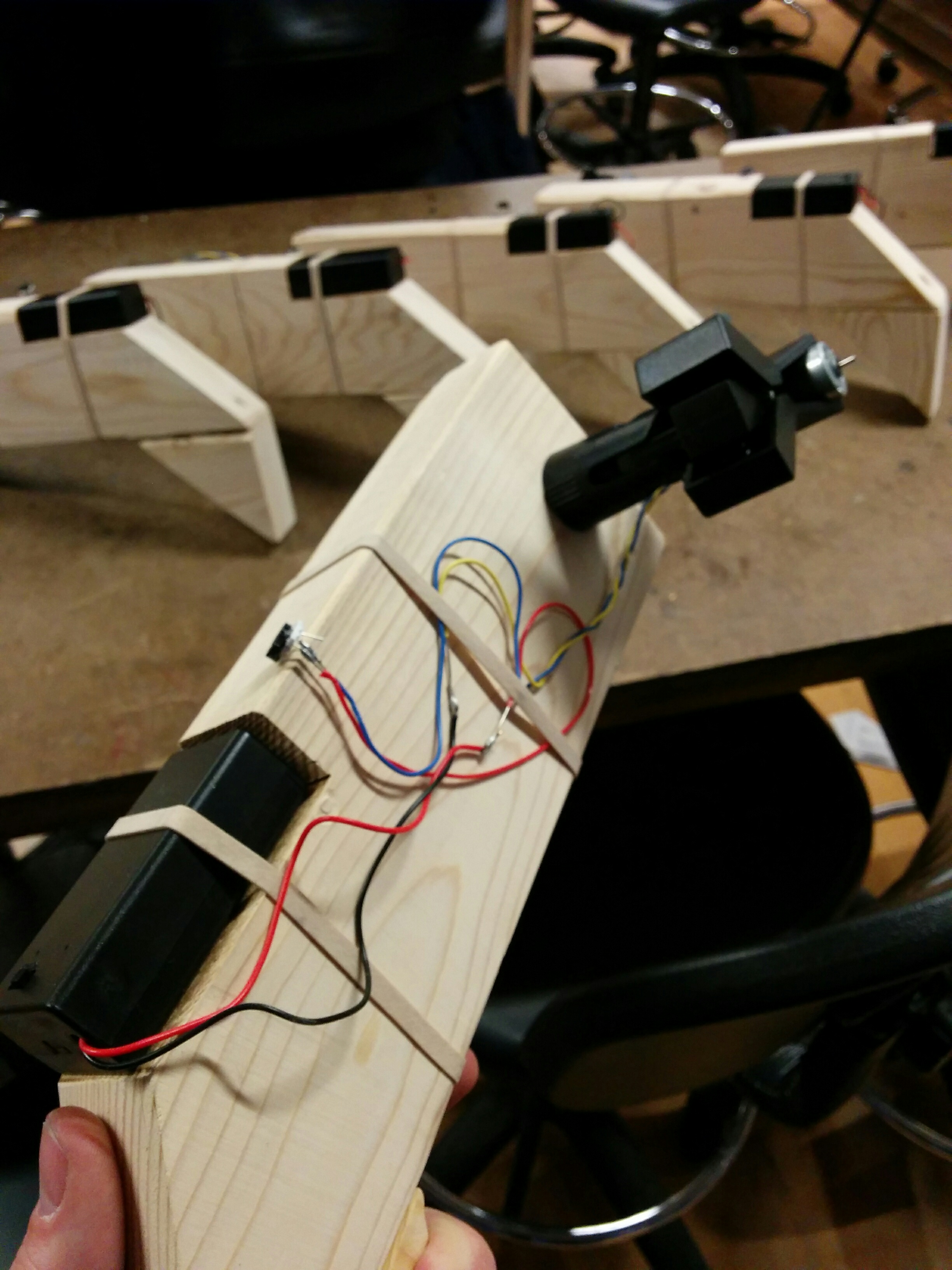
Motors! Battery cases! And just when I thought it couldn’t get any better, Ana hand delivered my batteries to the shop. Lets get these guys on!
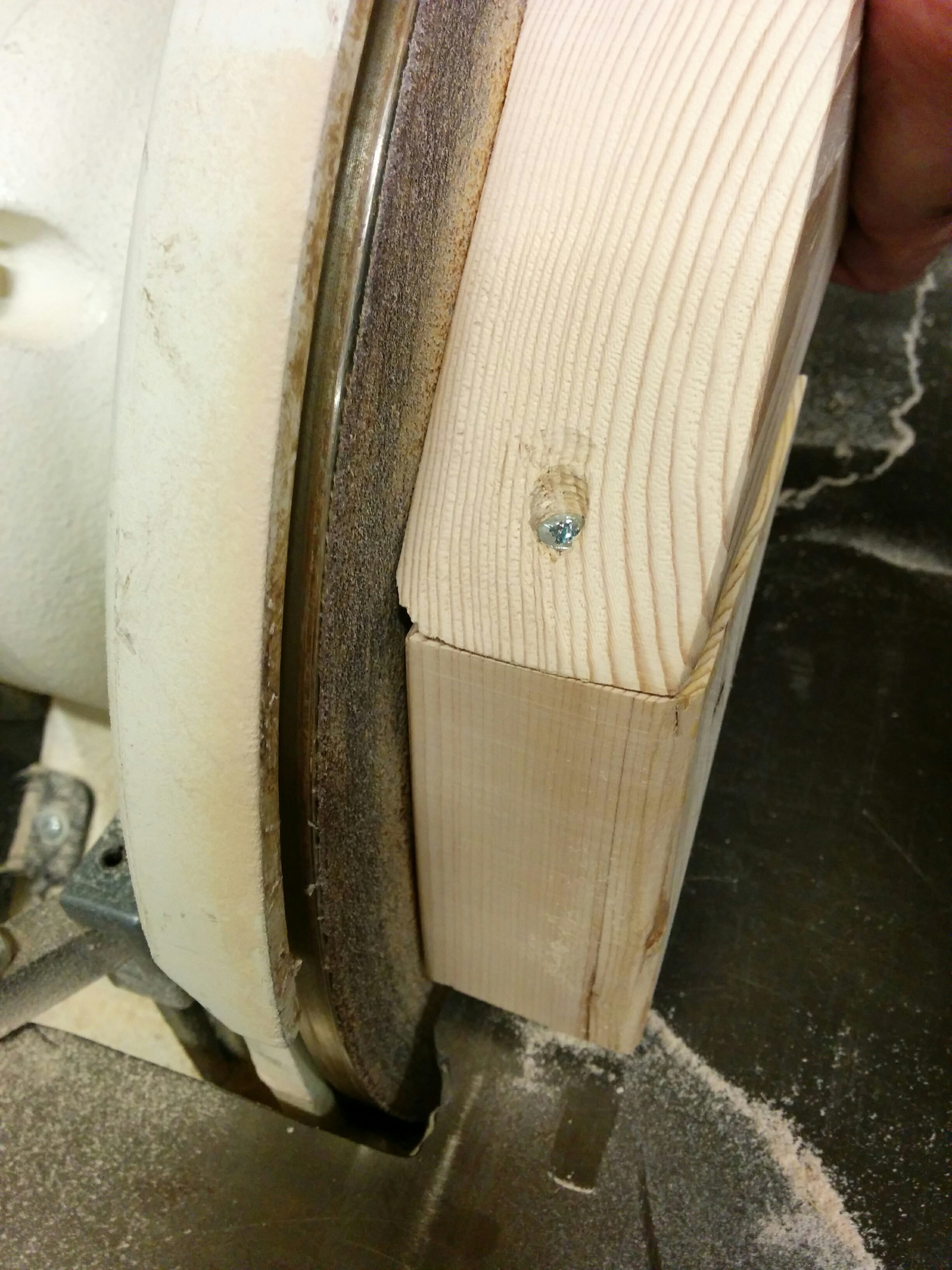
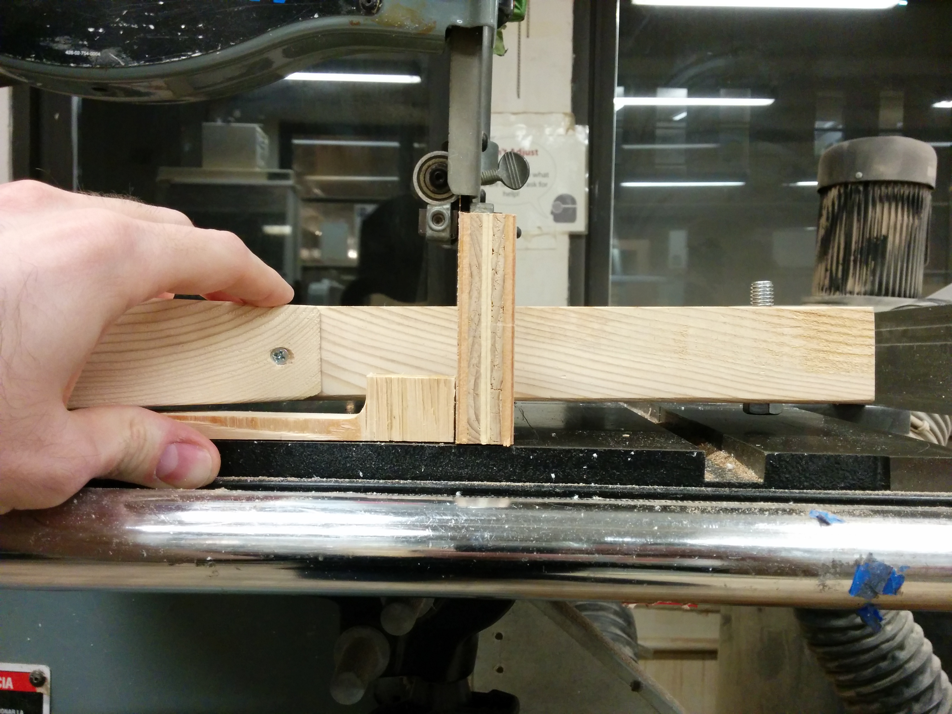
Of course, it would have been better to not have the screws in. But instead of undoing and redoing those, I found some wood scraps to elevate as I cut.
With my first test set, I was ready to duplicate.
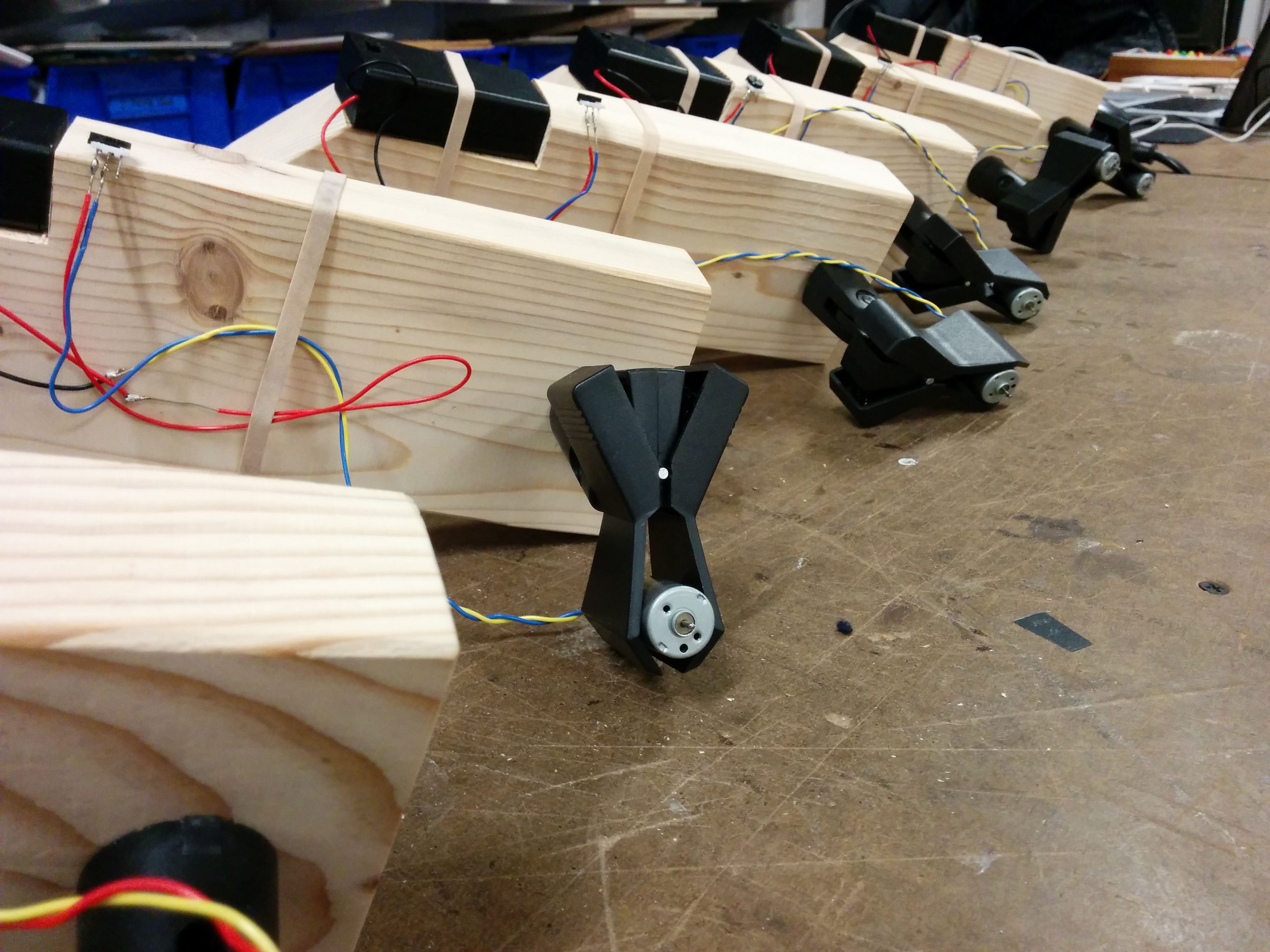
Lots and lots of soldering for the wiring
The final product(s)
I had some material I was trying to attach to the motor in order for it to hold different percussive mediums (brush, wire, etc). However, that did not work out that well. I think I’m going to set these aside for now and perhaps take more time in approaching that specific feature in more detail later.
*Phew!* I got something to show tomorrow. Certainly learned a lot. Can’t wait to discuss more and see what the rest of the class has cooked up.
And that concludes the thrilling tale of The Multiples!
This week’s homework was about loading and manipulating media. There were bonus points for not doing a video mirror or a sound board, so I decided I was going to avoid that.
To completely reduce the temptation, I wanted to load video clips instead of rely on webcam footage. Using the techniques Allison outlined in class, I wanted to address each pixel in these loaded videos to either display them or use their information to inform functionality.
I spent a lot, a LOT of time figuring out what videos would play nice with p5js. Many, many trips back and forth to and from Windows Movie Maker, cutting the length, shrinking the size, reducing the bitrate. I had a feeling that this might have been an issue with the online editor specifically, but in any case I was ready to deal with that limitation. After getting the video to play normally, I was ready to start analyzing each frame and draw.
I was getting some inconsistent crashes with errors like these: “Exiting potential infinite loop at line 36”. It seemed to take issue with the for loops that were going through the frames, but it’s behavior was making me wonder if p5 was simply stalling out when faced with too large of a task. And now that I type this out, I realize that I haven’t had these errors with my desktop PC, only my laptop.
Being able to analyze the contents of the pixels and make decisions accordingly was of great interest. In playing around with what was possible, I wound up making somewhat of a ‘bonus’ sketch just to see if I could:
It isn’t pretty, it isn’t smooth, but it is technically a functional green screen.
With my meme break out of the way, I used my newfound pixel hunting abilities towards a more serious piece.
I have some NASA footage of a spaceship-level view of the earth. It needed to be downsampled a great amount in order for it to find it’s way into p5, but it wound up being ok for my purposes. This sketch loads the video, and then displays the video in a lower res field of dots. If you move your mouse, you can adjust the shape. As all sketches start with the mouse at 0,0, it can look like nothing at first and then dramatically stretch into view upon interaction.
Pixels in the video are analyzed and placed as circles. If the program detects that the given pixel is above a certain threshold of whiteness (in this case, the clouds), those white circles are larger than the ones that are not white. Then there is a “scan line”. It is an area defined in the sketch that is looking for these larger white dots. If there is a larger white dot detected in this area, it is highlighted with a green circle. A droning note is played with a different pitch depending on it’s location on the X axis.
There are still some bugs. As I moved development to my desktop, upon returning to the laptop it seems I cannot run the sketches. This is why I have added videos of the sketches running, just in case they cannot be seen on the presentation laptop. Also, when running smoothly, the NASA video sketch doesn’t always play the notes with the correct pitches. It appears that if you use the rate() and play() too rapidly in a row, sometimes the rate() command is ignored and the sound file is played at the original speed.
However, despite these setbacks, I am happy with the conceptual end result. I am interested in different ways to communicate data, and the idea of data “sonicalization” as opposed to visualization seems like an intriguing pursuit. Something like this could measure weather patterns, the health of a forest, or air quality conditions. The stylized output, visually and aurally, might create new opportunities to motivate people to digest these findings.
After completing our midterms, we came away with a lot of real good experience in terms of feeling what is and isn’t possible within a certain time frame. With these lessons in mind, we are now given more time to complete our final projects and more specifically plot out our goals, intentions and options. The first part is clear ideation of what we might want to build, so we can discuss feasibility and research solutions.
For a while now, I’ve had an idea for a device that I have wanted to create. Essentially, it is a “cuff” that would fit around a microphone that would have different inputs on it. This would allow for the person using the microphone to control actions of a computer in their performances. Seeing as there are all kinds of “digital accompaniment” ranging from Power Point slide shows to full on theatrical lighting rigs, I thought that giving the speaker or singer more direct control could help create more of a direct feedback loop. One that isn’t broken by visits to a laptop keyboard, mediated by a tech person behind a big board, or ones that don’t exist at all because a performer has to keep up with a pre-made track.
The basic approach is that of enhancing the basic mic clip. If there were inputs on it, a performer could use them. If it was built like a standard mic clip, it could fit all standard sized microphones. With proper matching software, it could adapt itself for all different kinds of applications.
Part of our first step is research, and seeing what already exists. I didn’t know if it, but I wasn’t surprised to see something like this:
I’m intrigued by it, but it strikes me as too proprietary, task specific, and expensive. I think that the capability of this should be able to be achieved by what I’m proposing through paired software, but not *only* fixed to the realm of manipulating the audio of that microphone.
I kept looking, not finding much more than that, until I found this.
There are always those moments where you say to yourself, “Damn… but I really *did* think of it on my own!” The overall approach here seems to be the direction I want to go in. A mic that sends data. However, as I kept watching, and researching, I became a little more optimistic. First, I don’t think these controls should be built into the mic itself. And second, this appears to have been issued as a prototype, but I haven’t seen it released anywhere (as of this writing).
So I think that perhaps the spirit is the same, but I have some important distinctions that I am opinionated about. I think having a proprietary mic that can do this is a mistake. Letting people choose their own preferred mic, and then temporarily enhancing its function is more flexible. Also, building the control only greatly reduces cost, which would make performers and presenters much more likely to try it. Additionally, with these aspects in mind, there could be a series of different kinds of layouts. If the costs were low enough, maybe there could be a variety of approaches: one with only buttons, the other with sliders, the other mimicking a piano key layout, etc. This might be able to cater to many use cases.
And this isn’t even bringing more complicated input and output, like bluetooth or accelerometers. But again, perhaps that approach can be more appropriate for some performers than for others. At the end of the day, my user is a vocal performer (yes, even the bland Power Point speech) that may need more interaction with their digital counterparts. I think even though there seems to be things that have kind of touched this realm, I haven’t yet come across something that is truly close to what I’m proposing when thinking about the microphone specifically.
Looking forward to bringing this idea to the class and seeing what people think.


