Intro to Fab 6: Mounting Motors

Our last assignment for class was working with motors: attaching them to things, and attaching things to them. There is a class at ITP called “If it moves, it breaks”, and I certainly now know why. Getting things to move can be a huge pain, even in my simple attempt.

In our second assignment, we were asked to make multiples of something. I had originally set out to make a kind of a musical instrument involving motors. At the end, I had everything I needed… besides something attached to the motors that could spin around and hit things to make sound. I knew we would be returning to motors later on in the semester, so I was happy to come back to the concept.

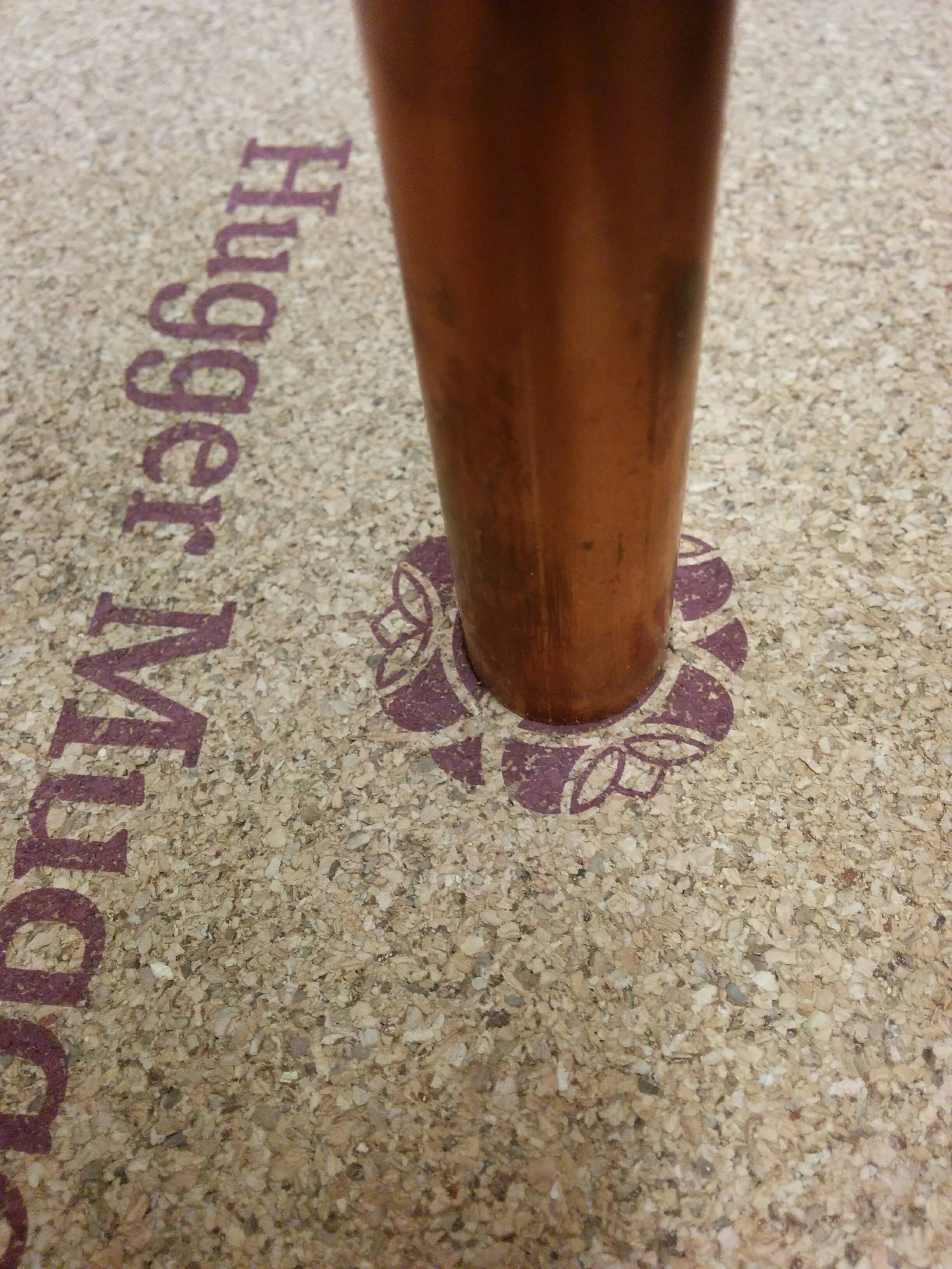
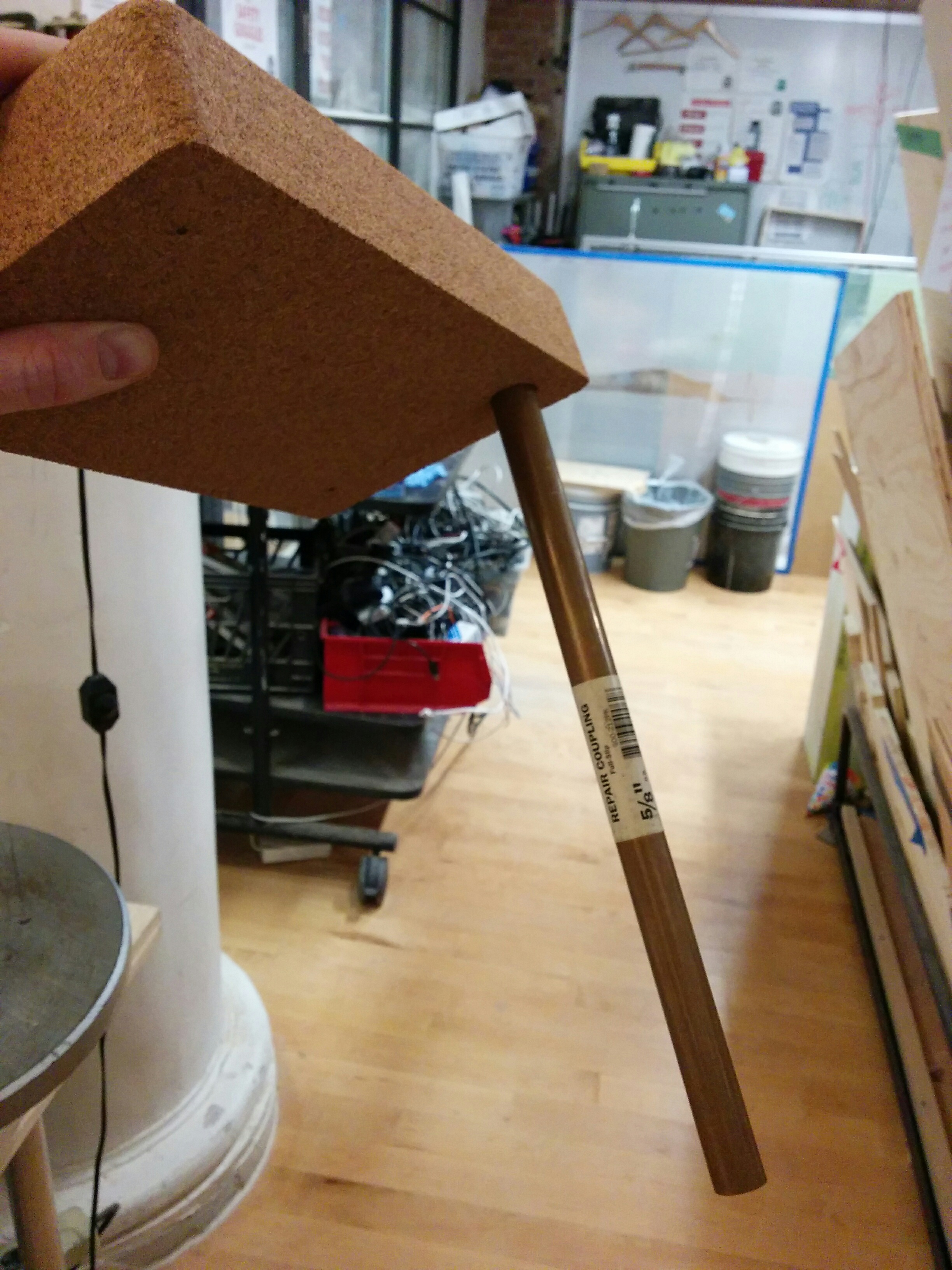
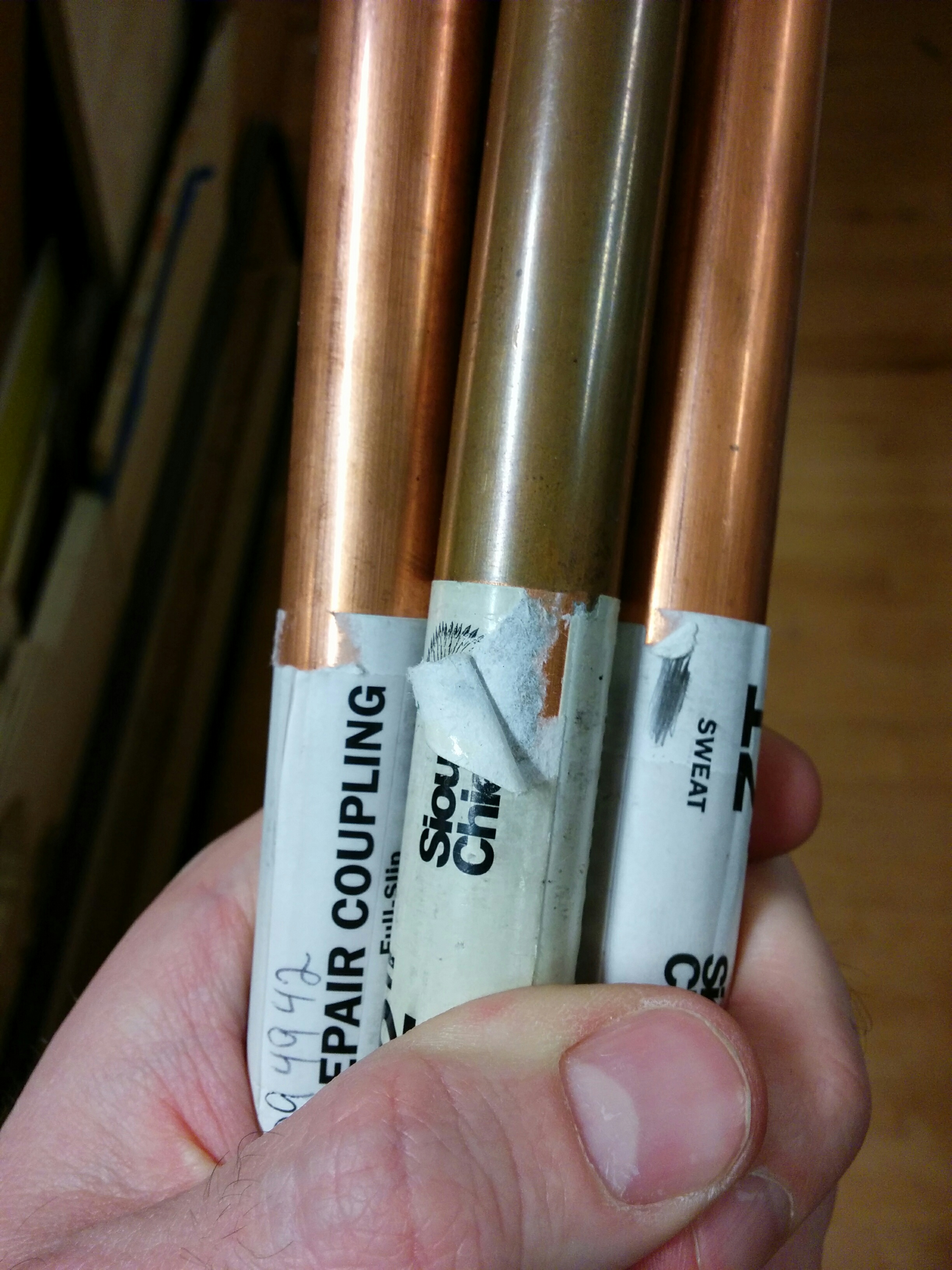
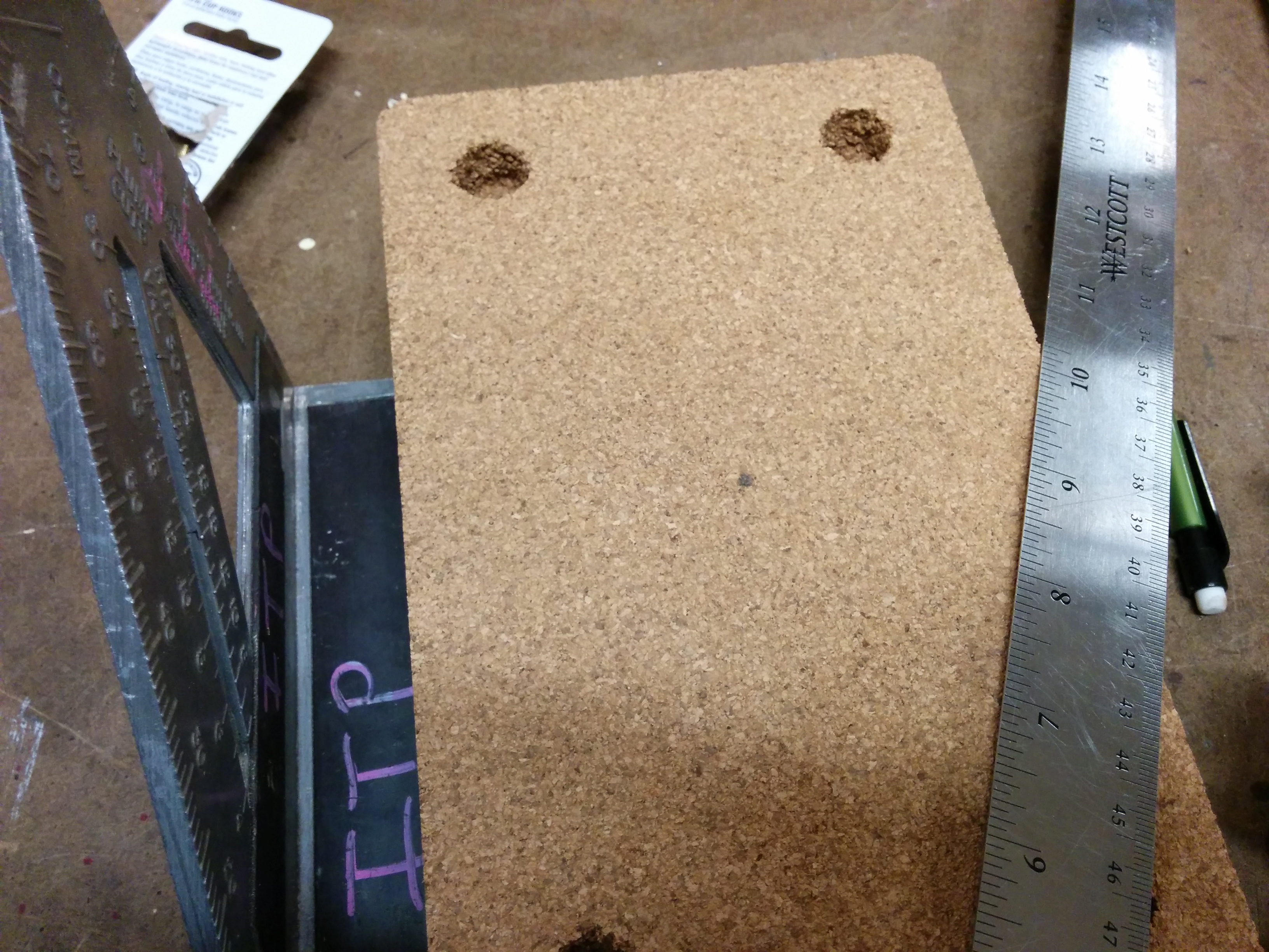
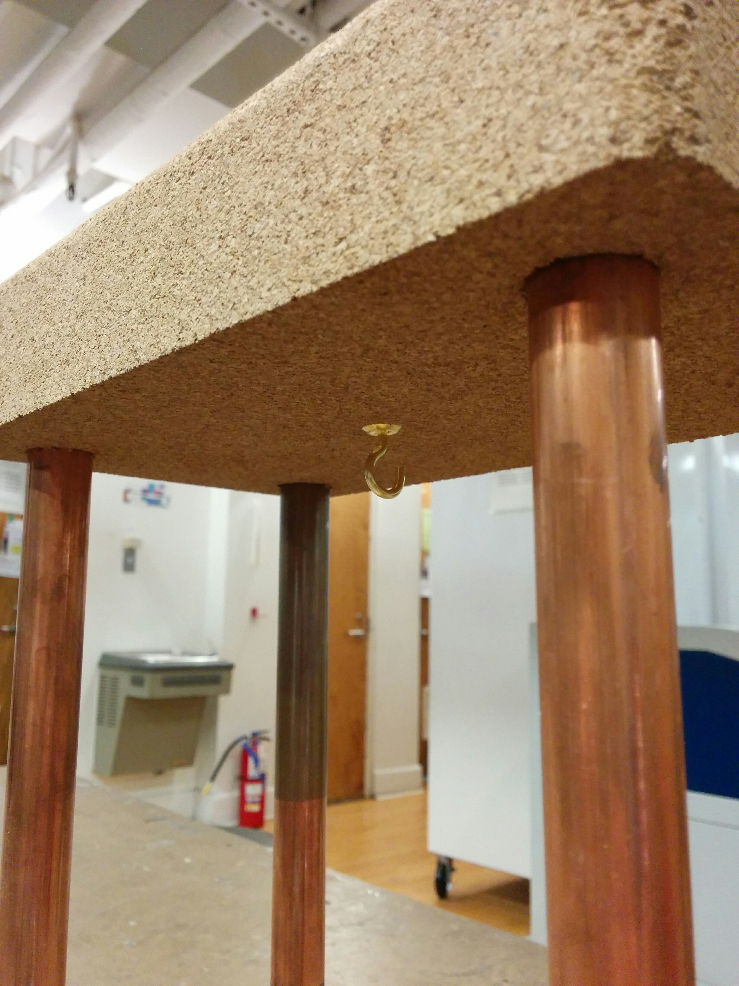
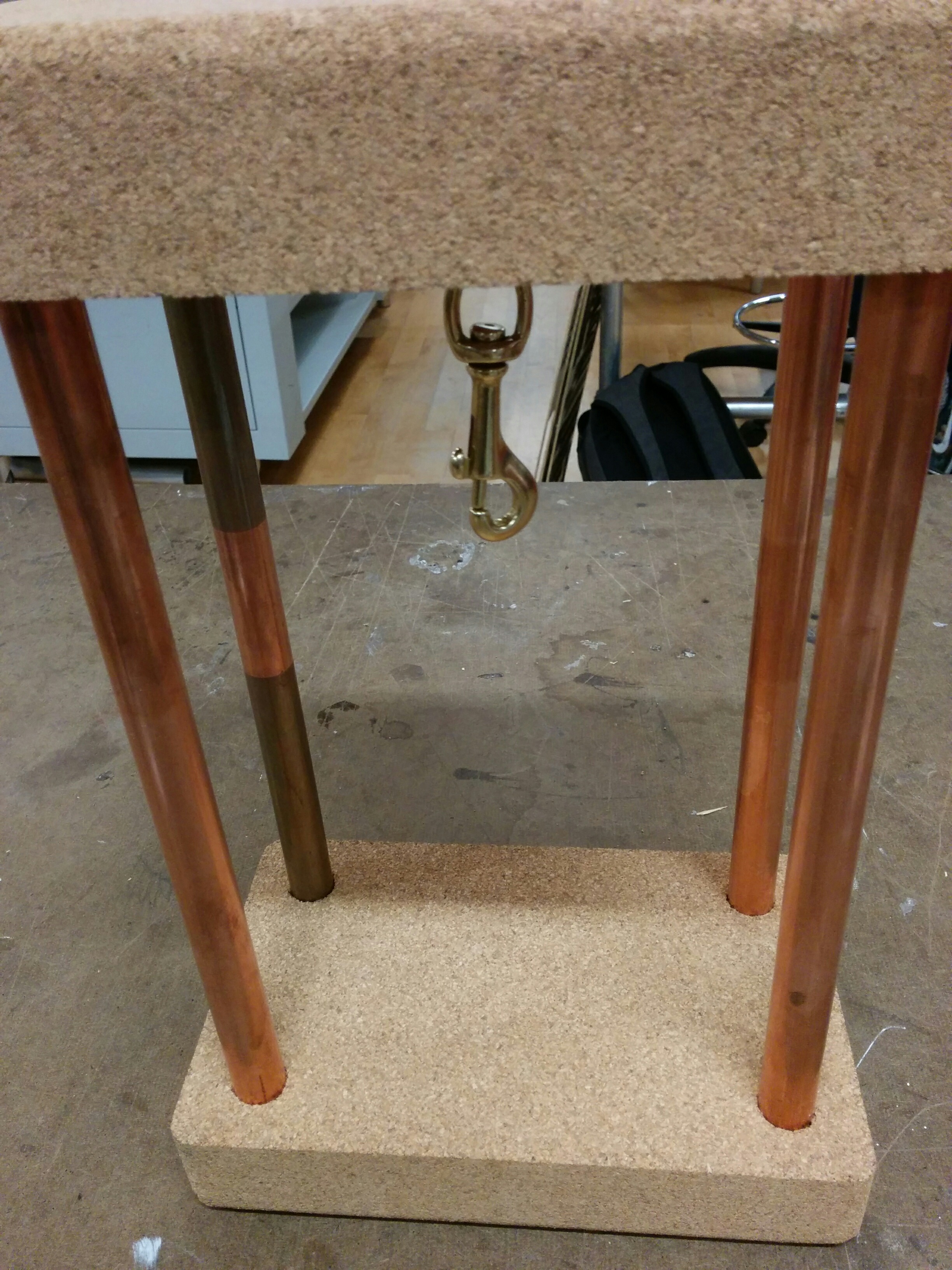
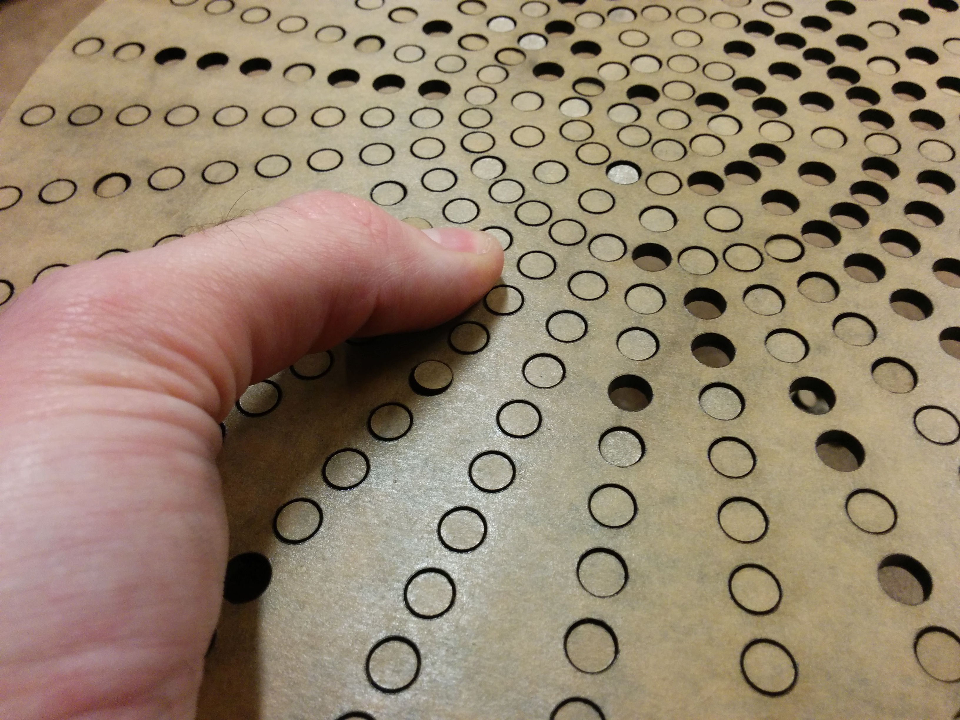
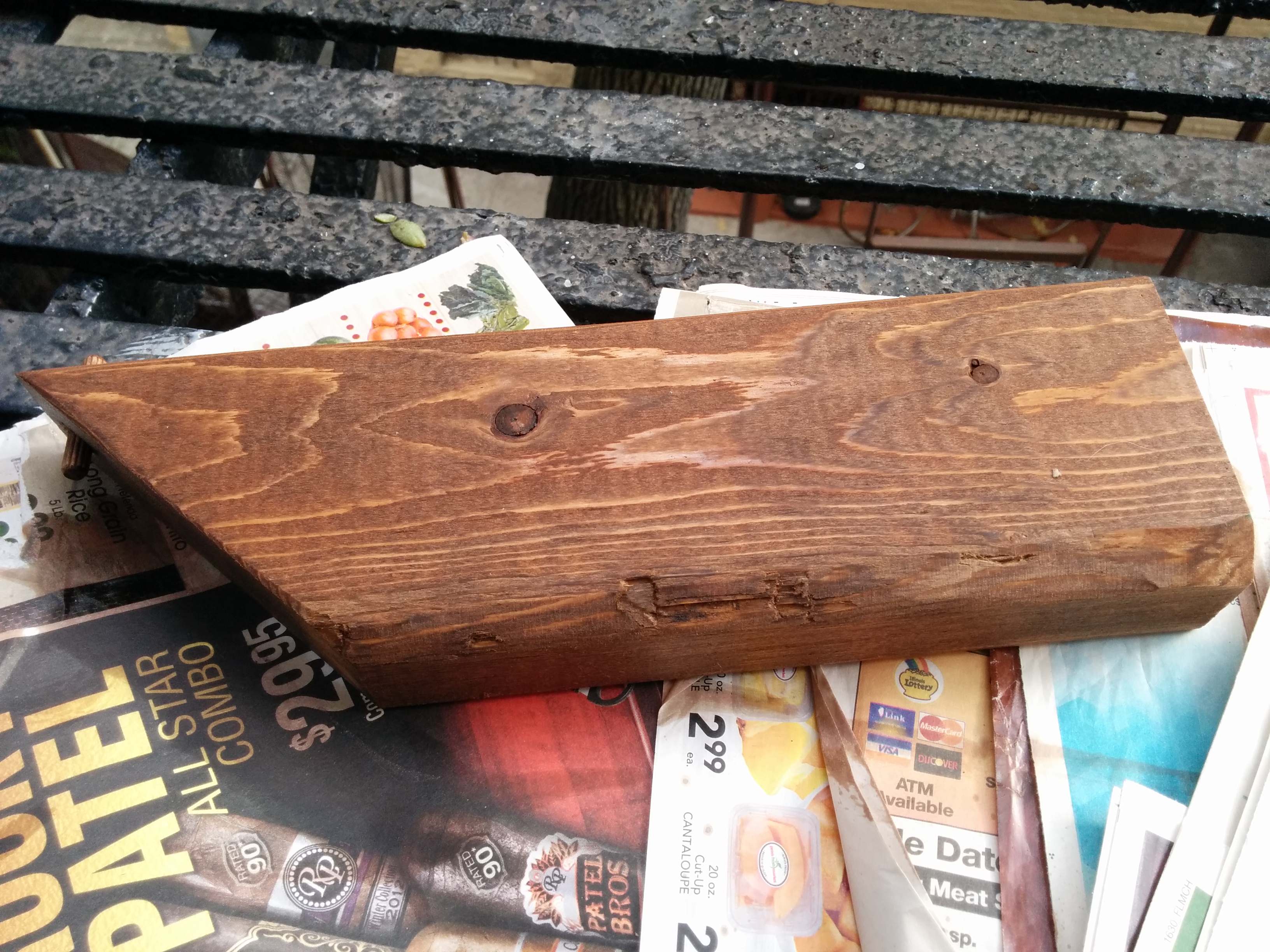
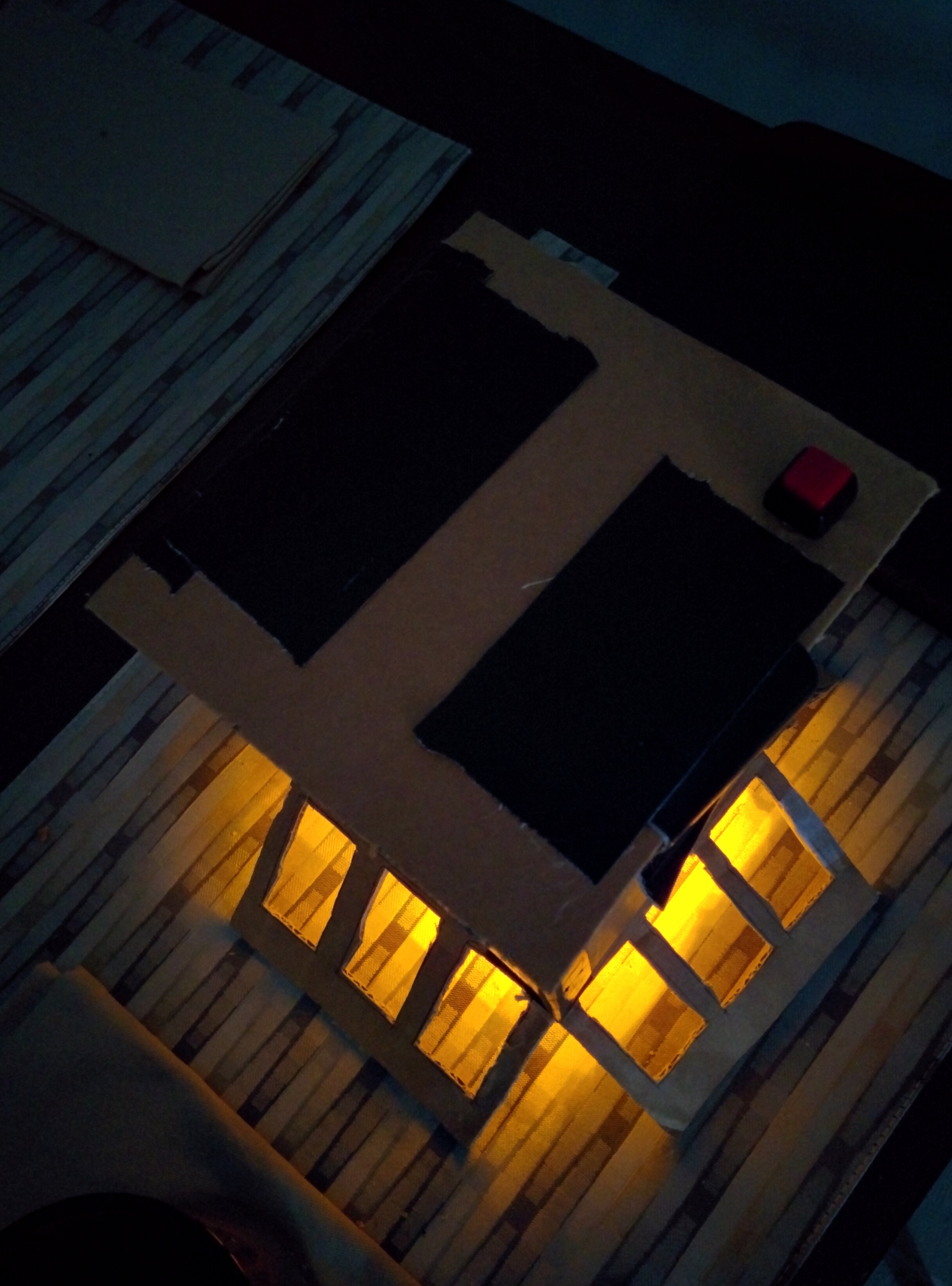
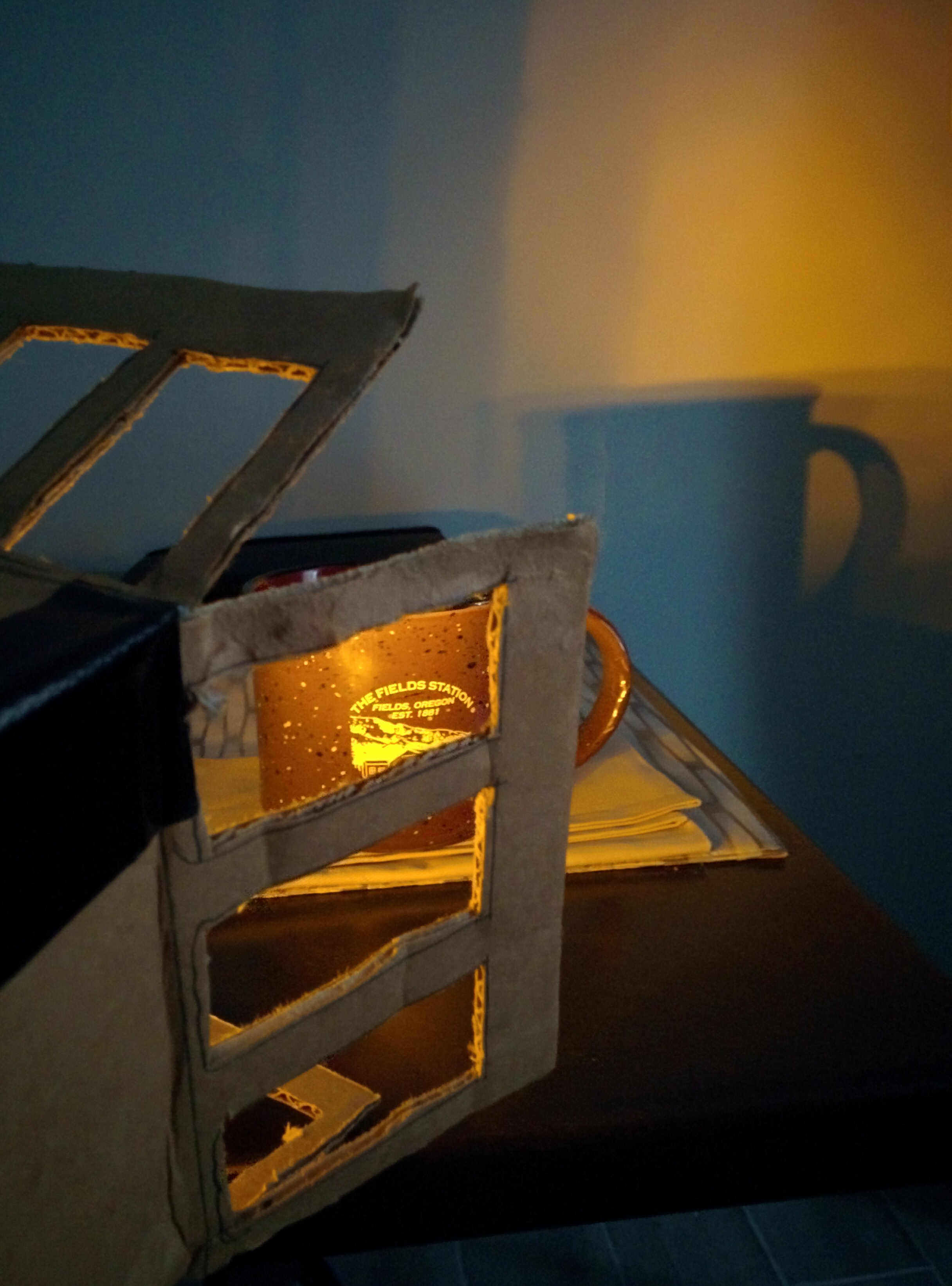
A different previous project also inspired me, which lead me to use cork again as a material. I went out and bought some materials and got started.

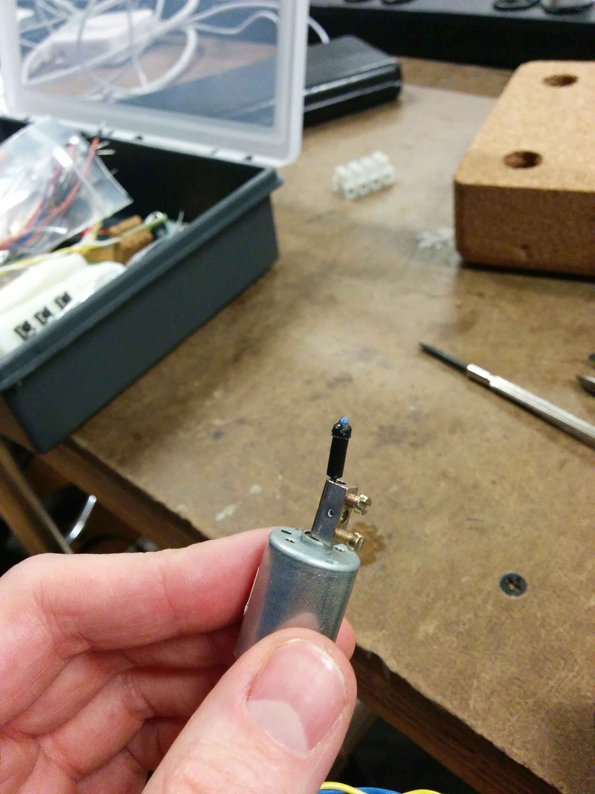
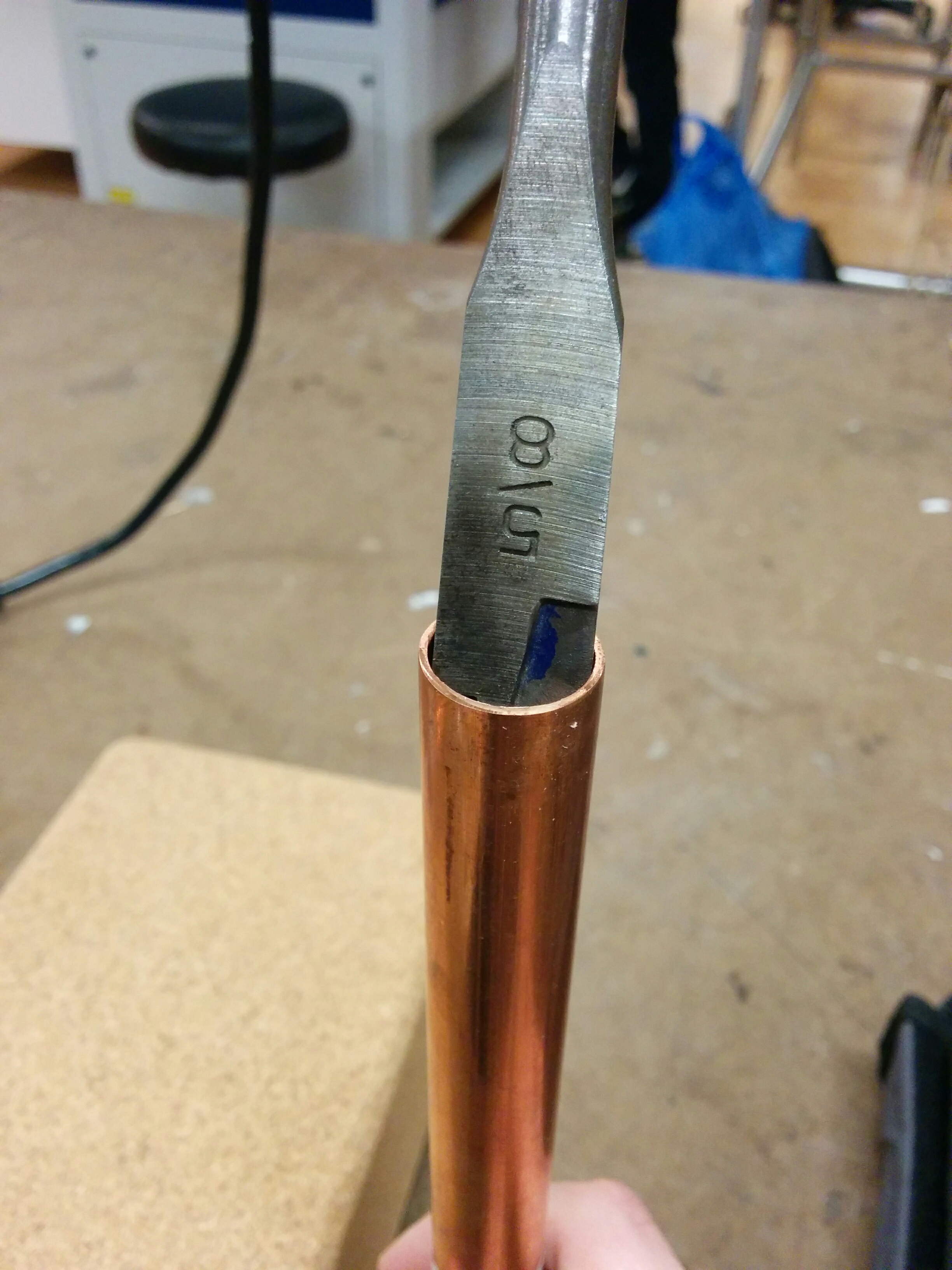
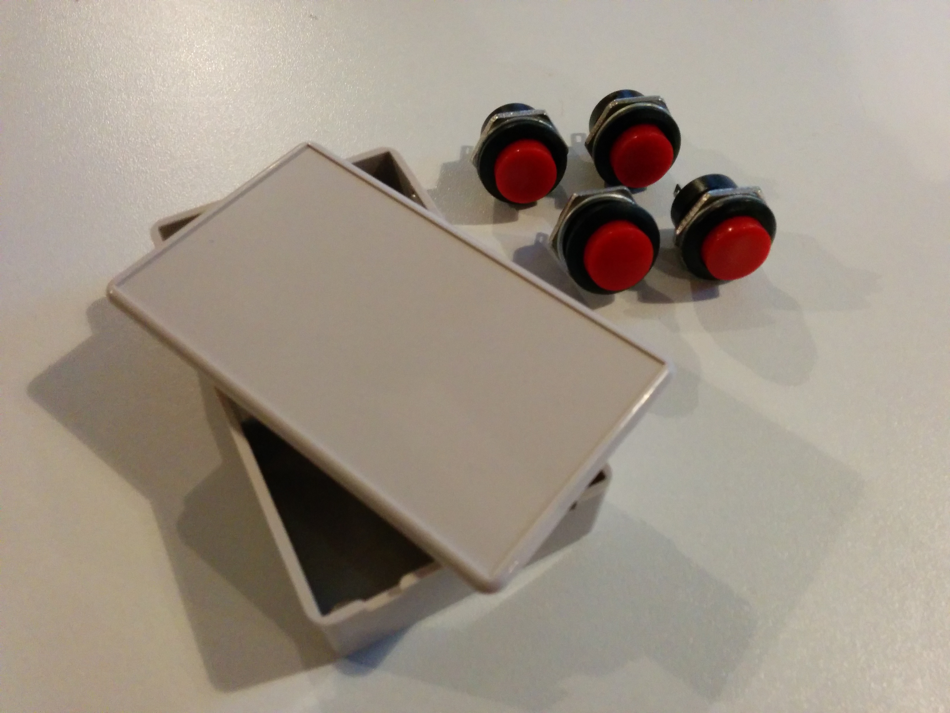
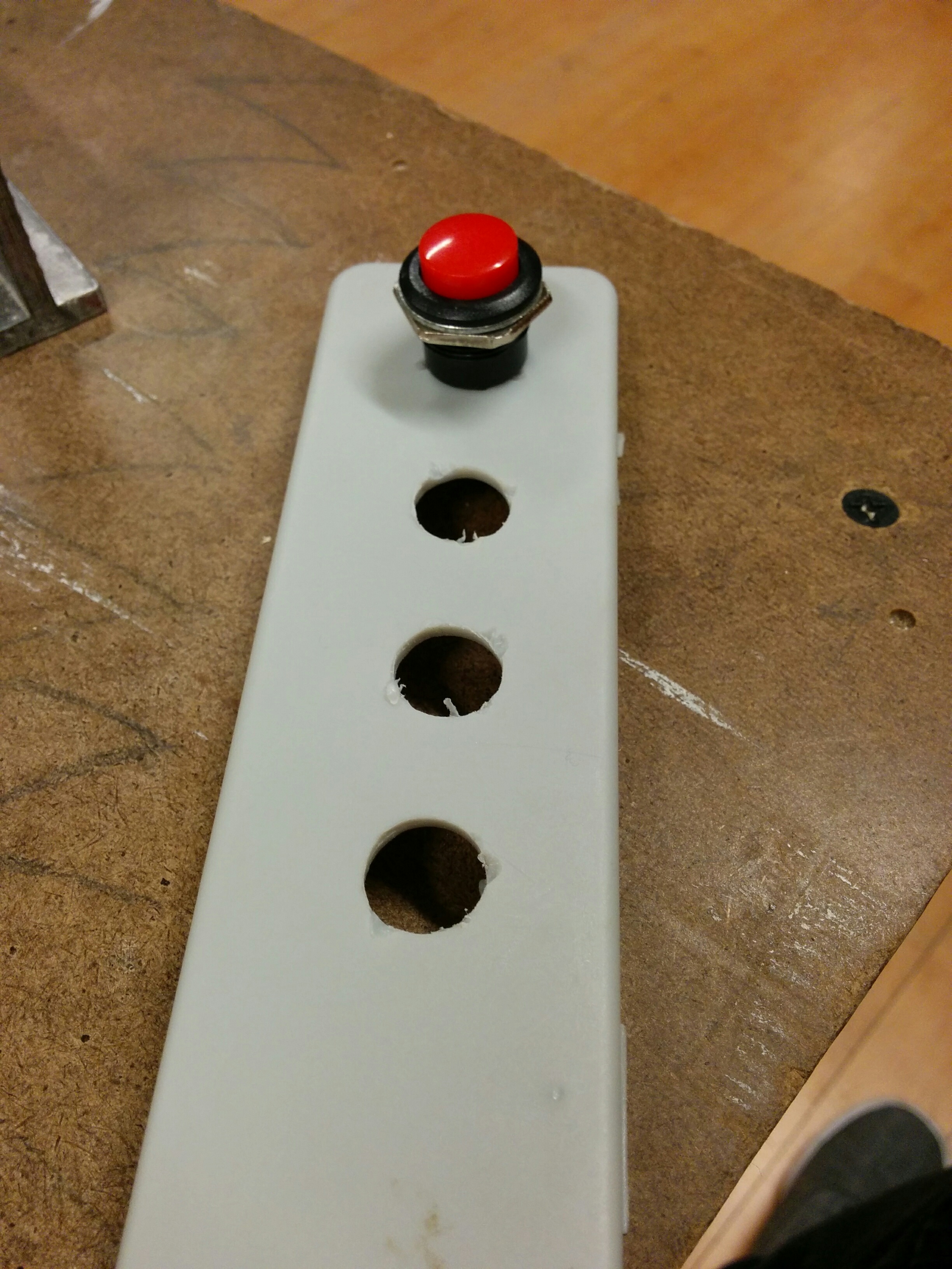
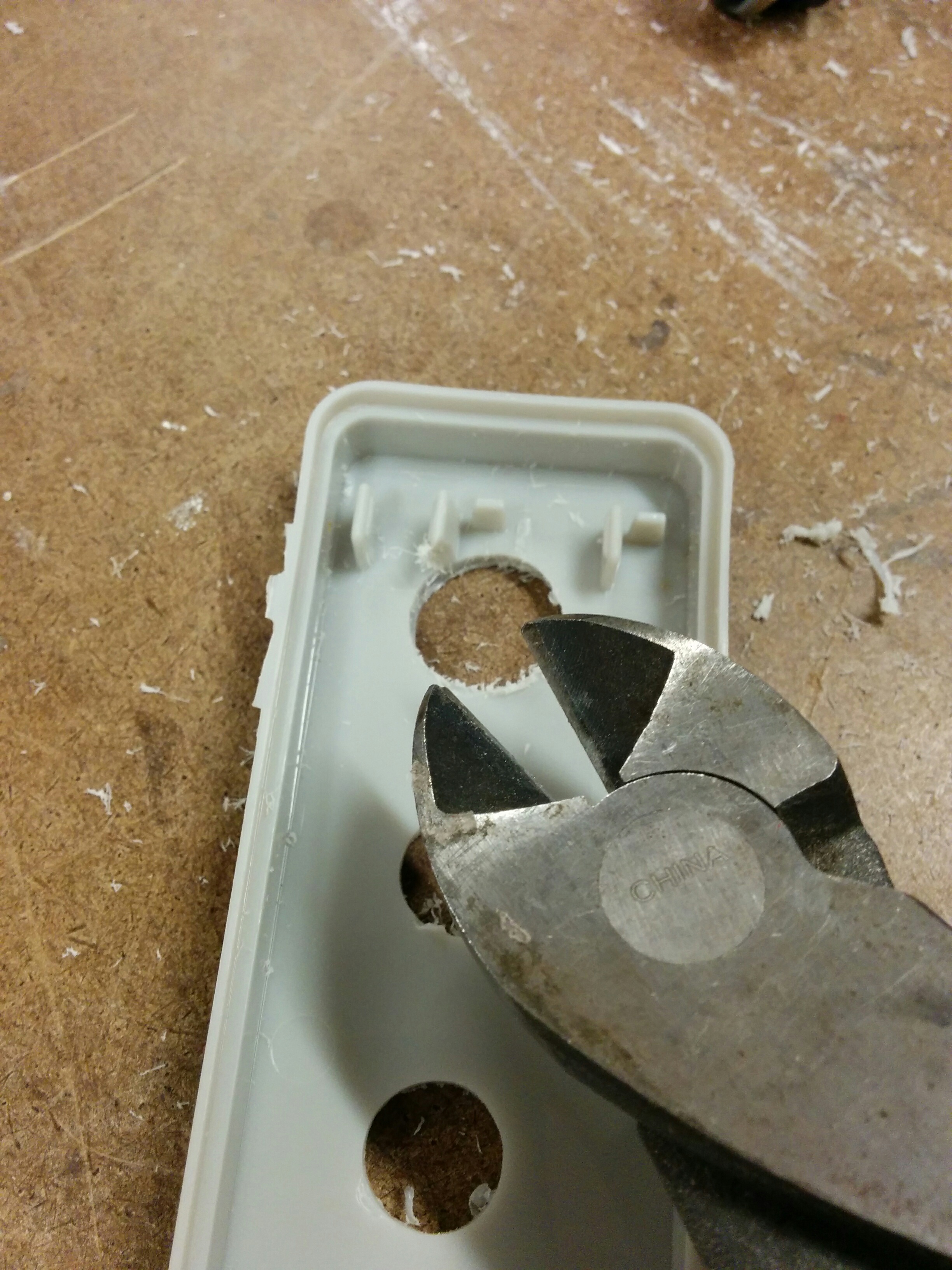
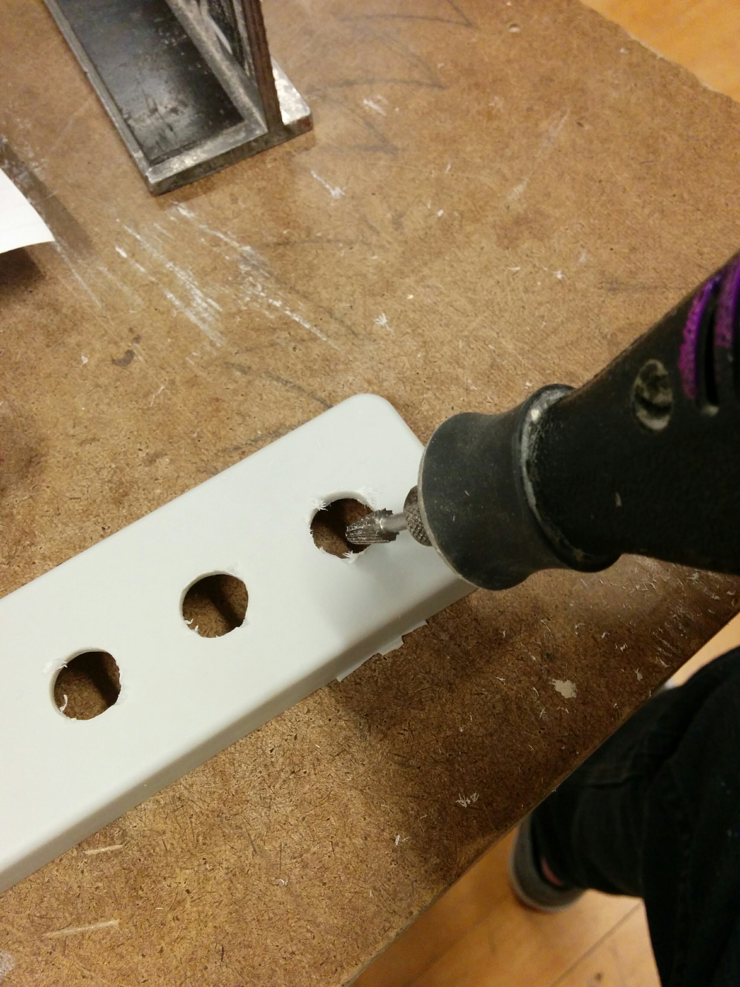
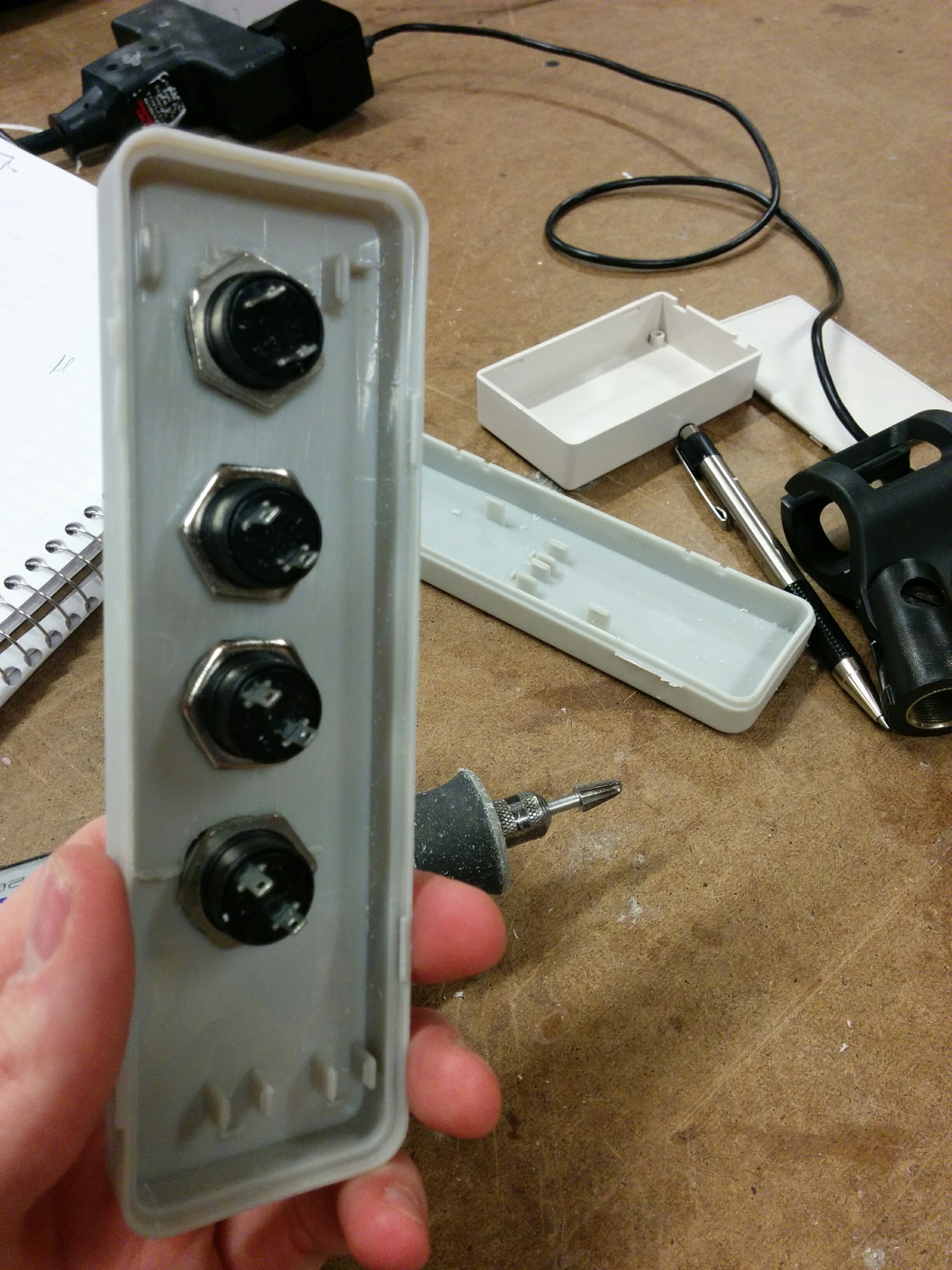
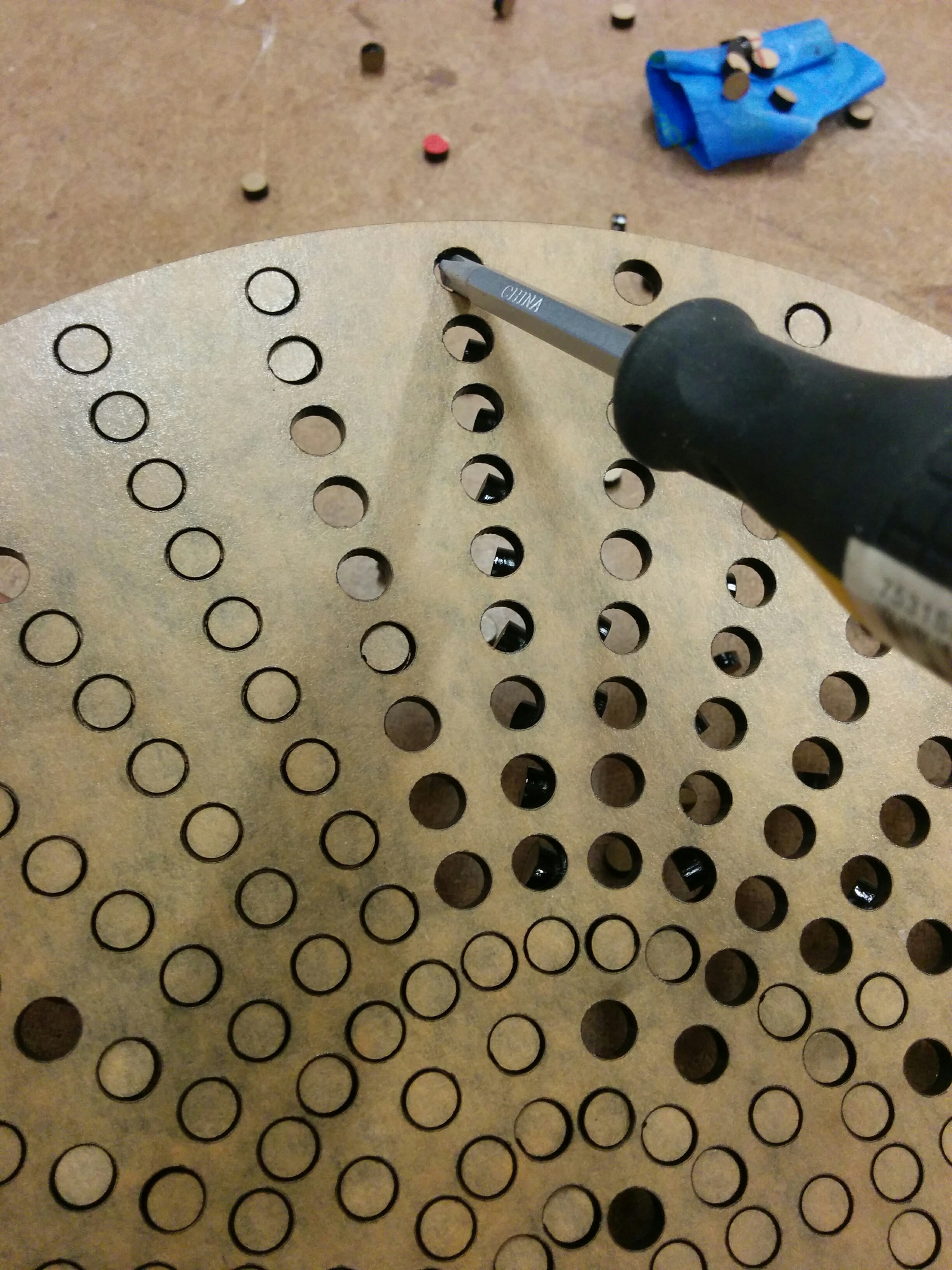
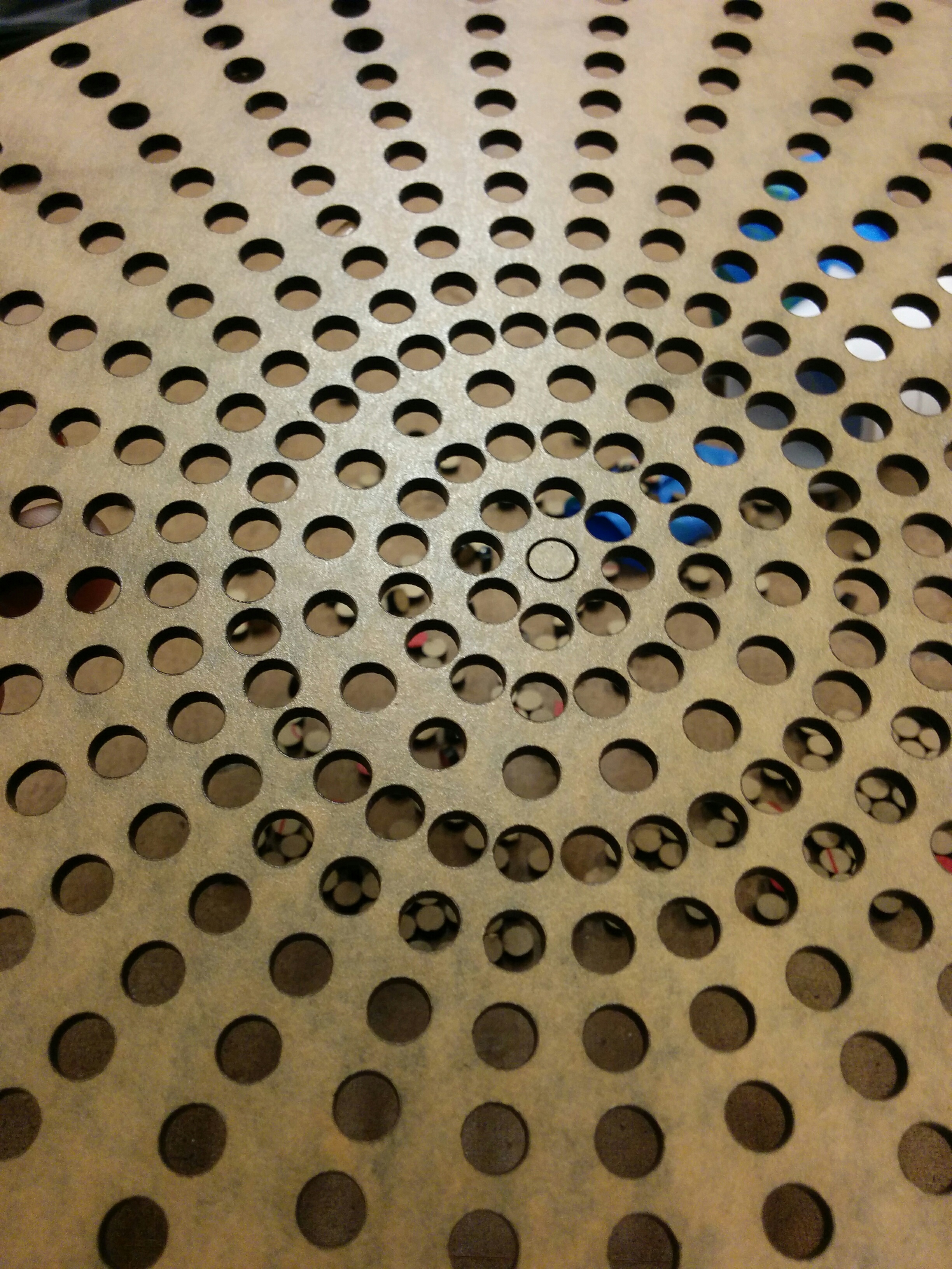
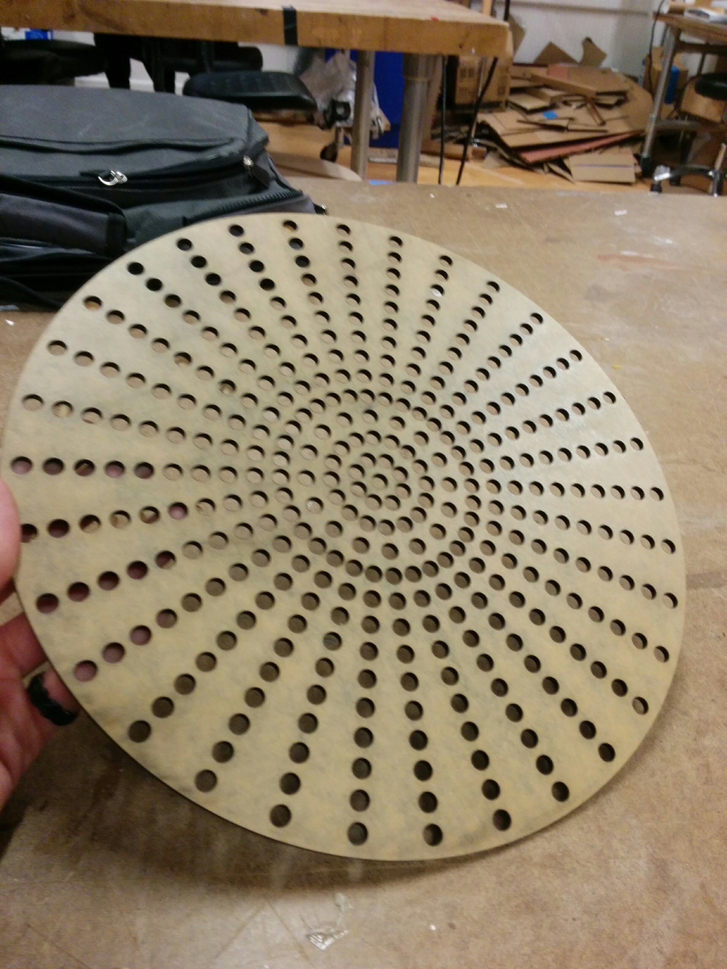
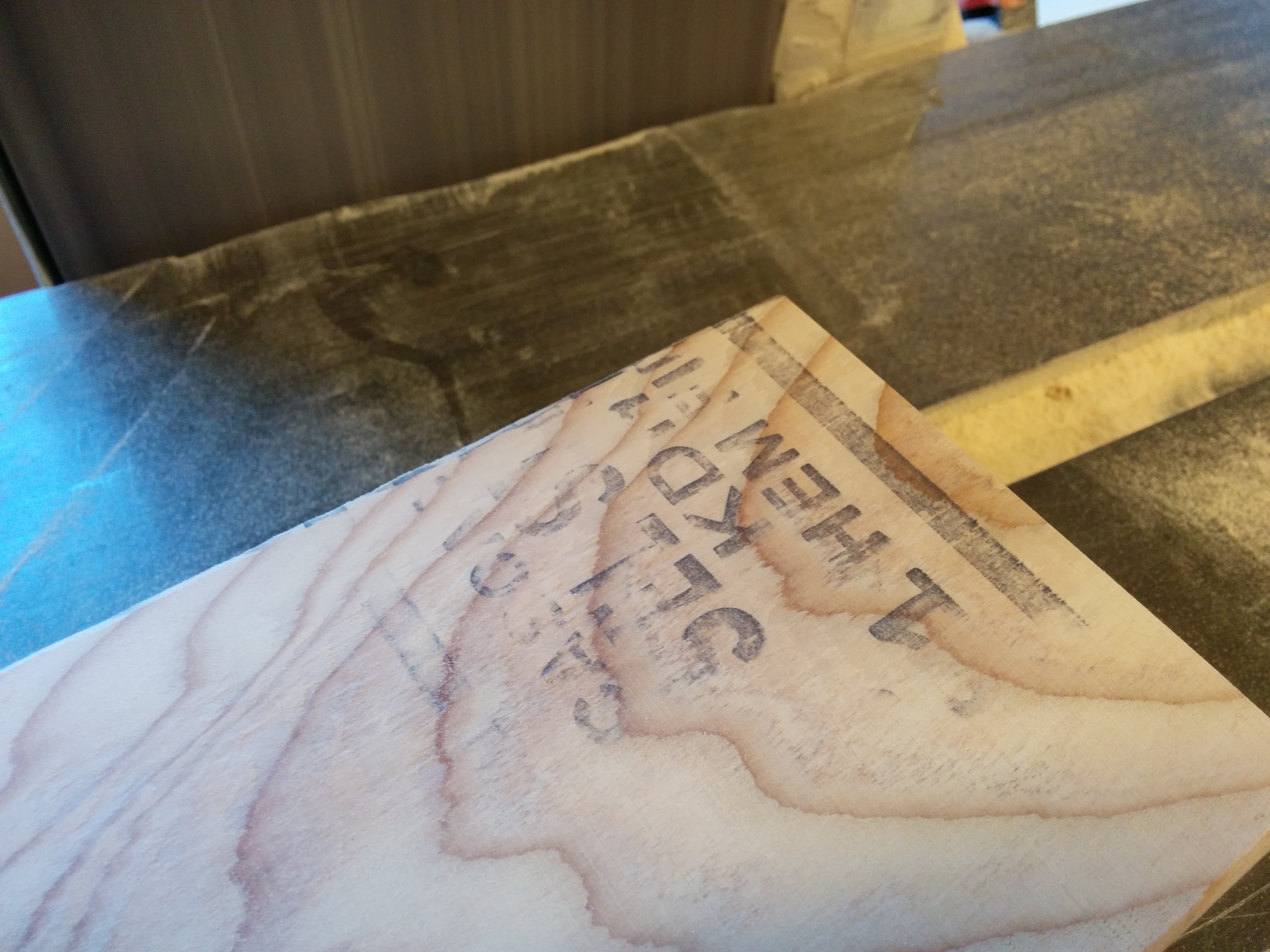
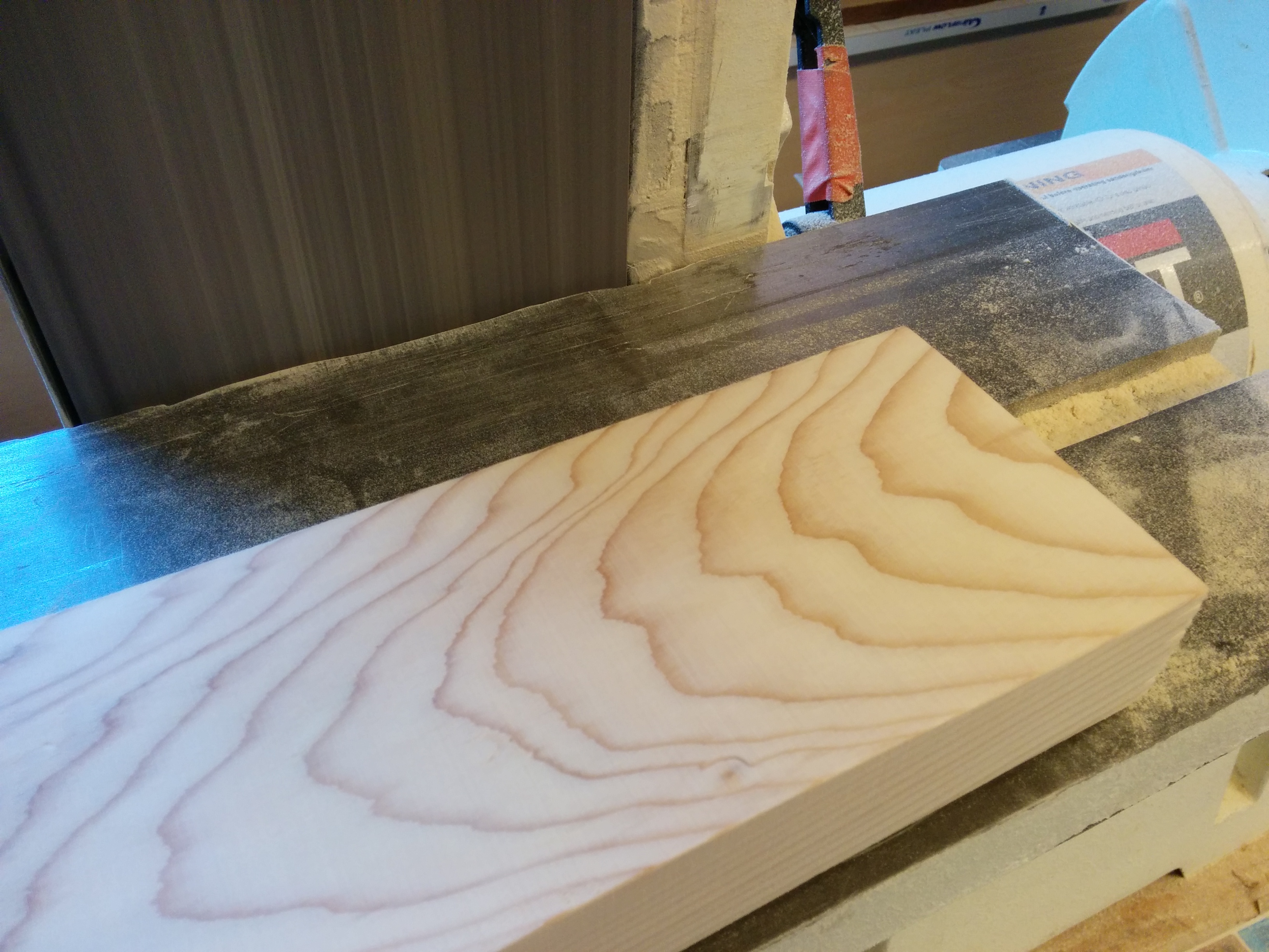
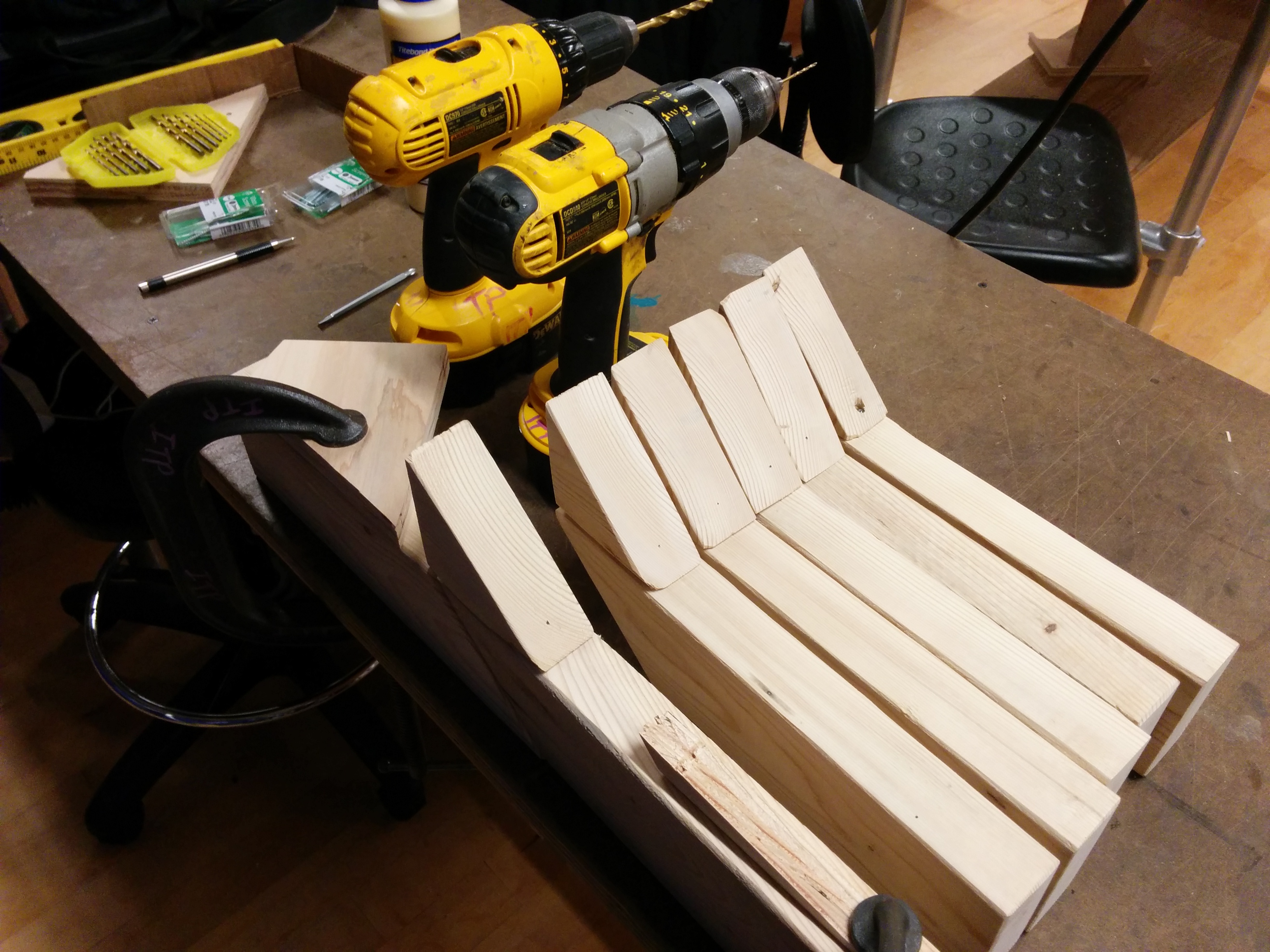
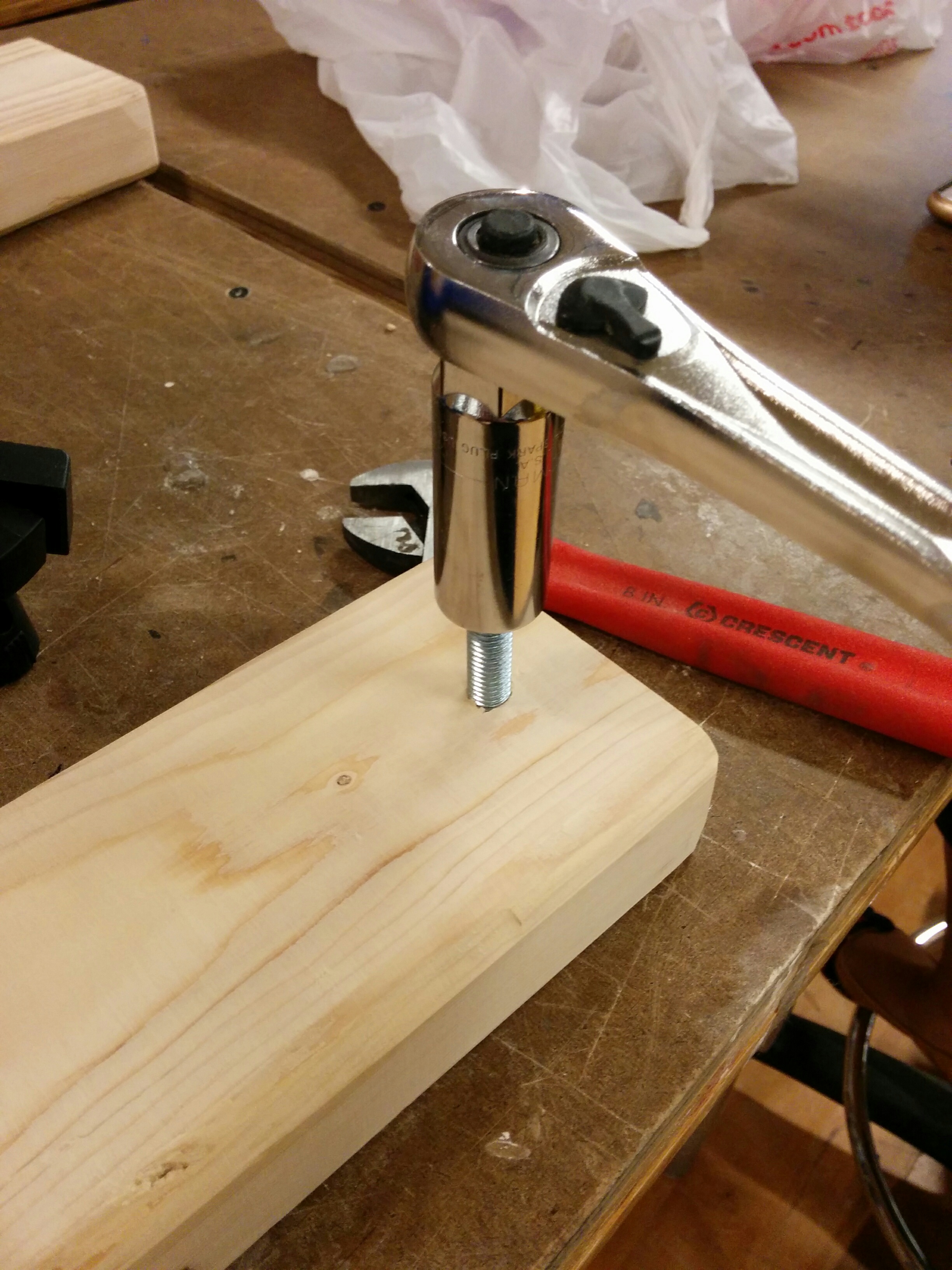
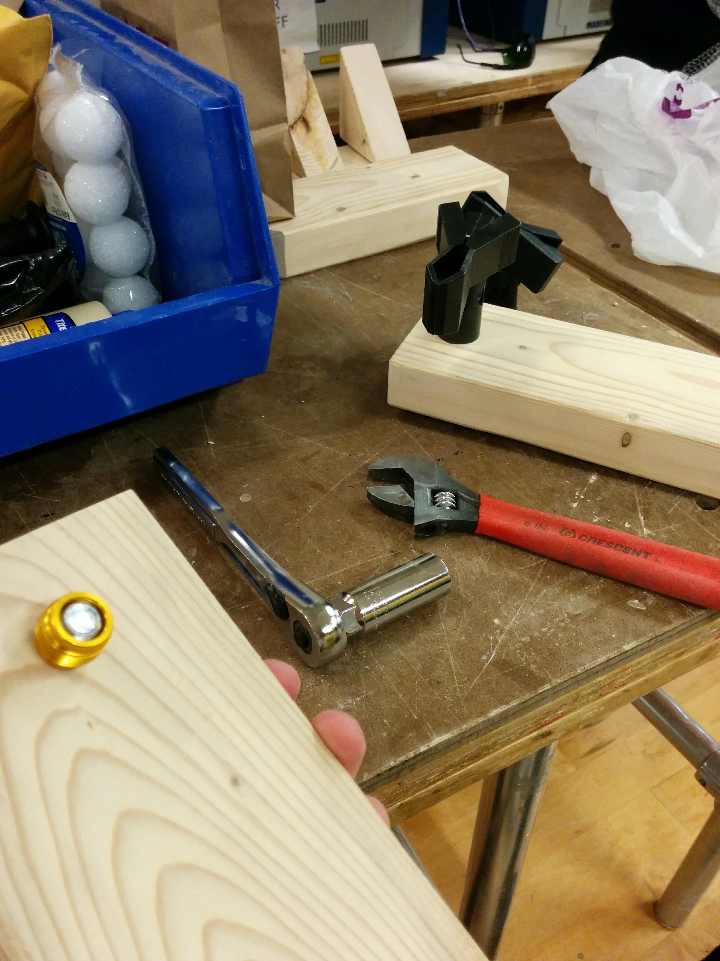
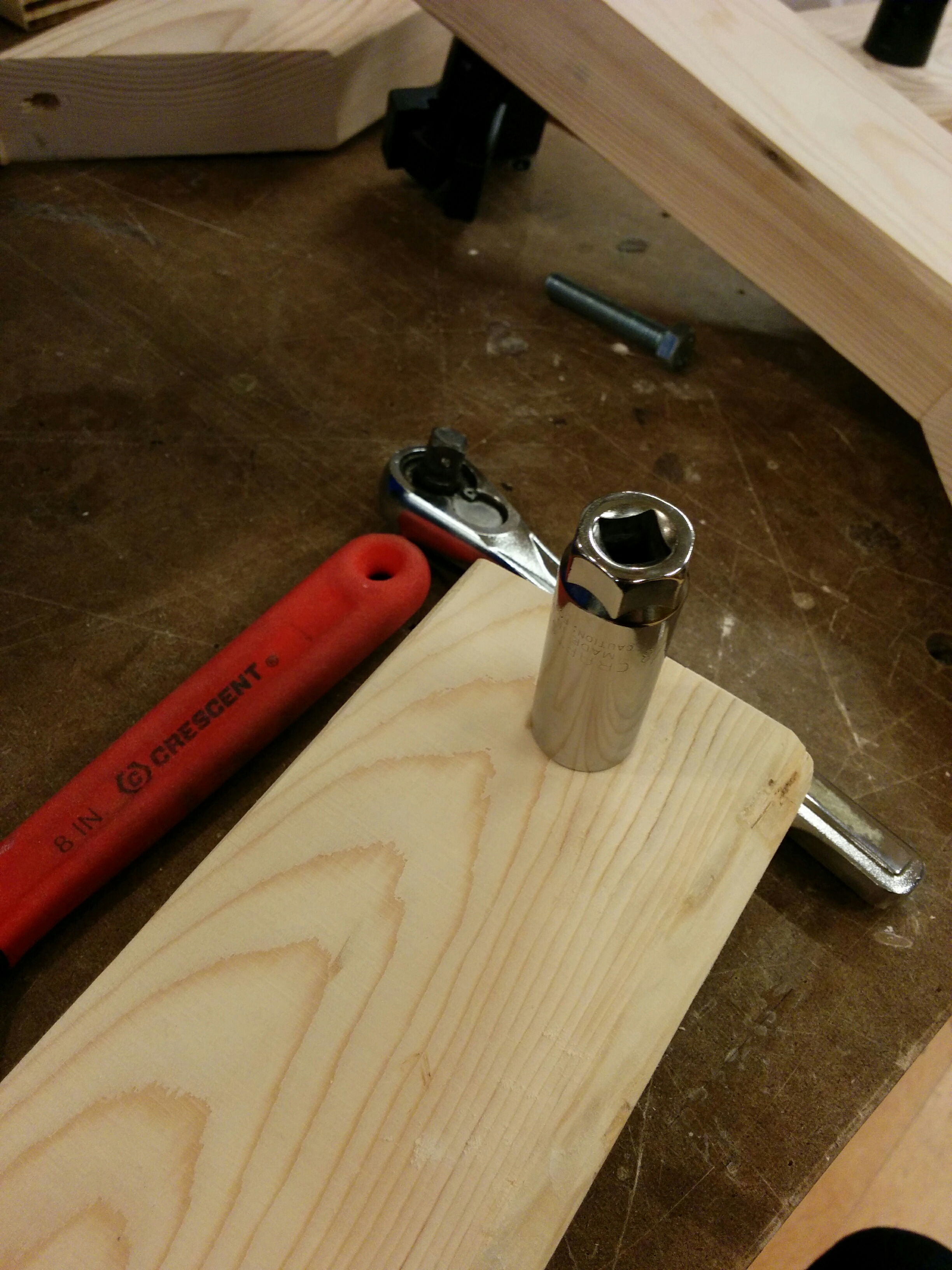
First was the screw block terminal, in order to get out the inner shaft couplers. I didn’t realize how easy it would be to damage the inner components by sanding too much.

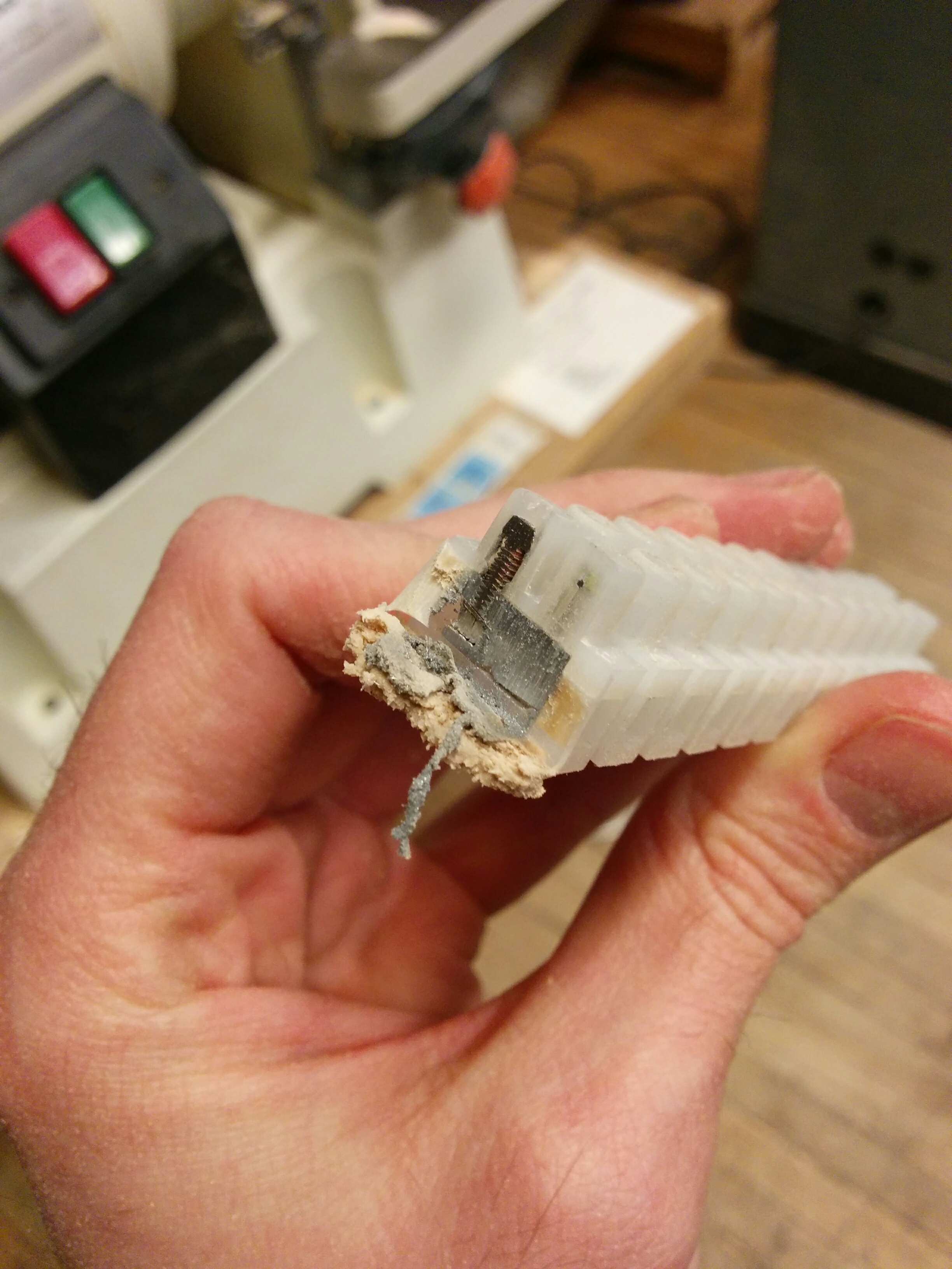
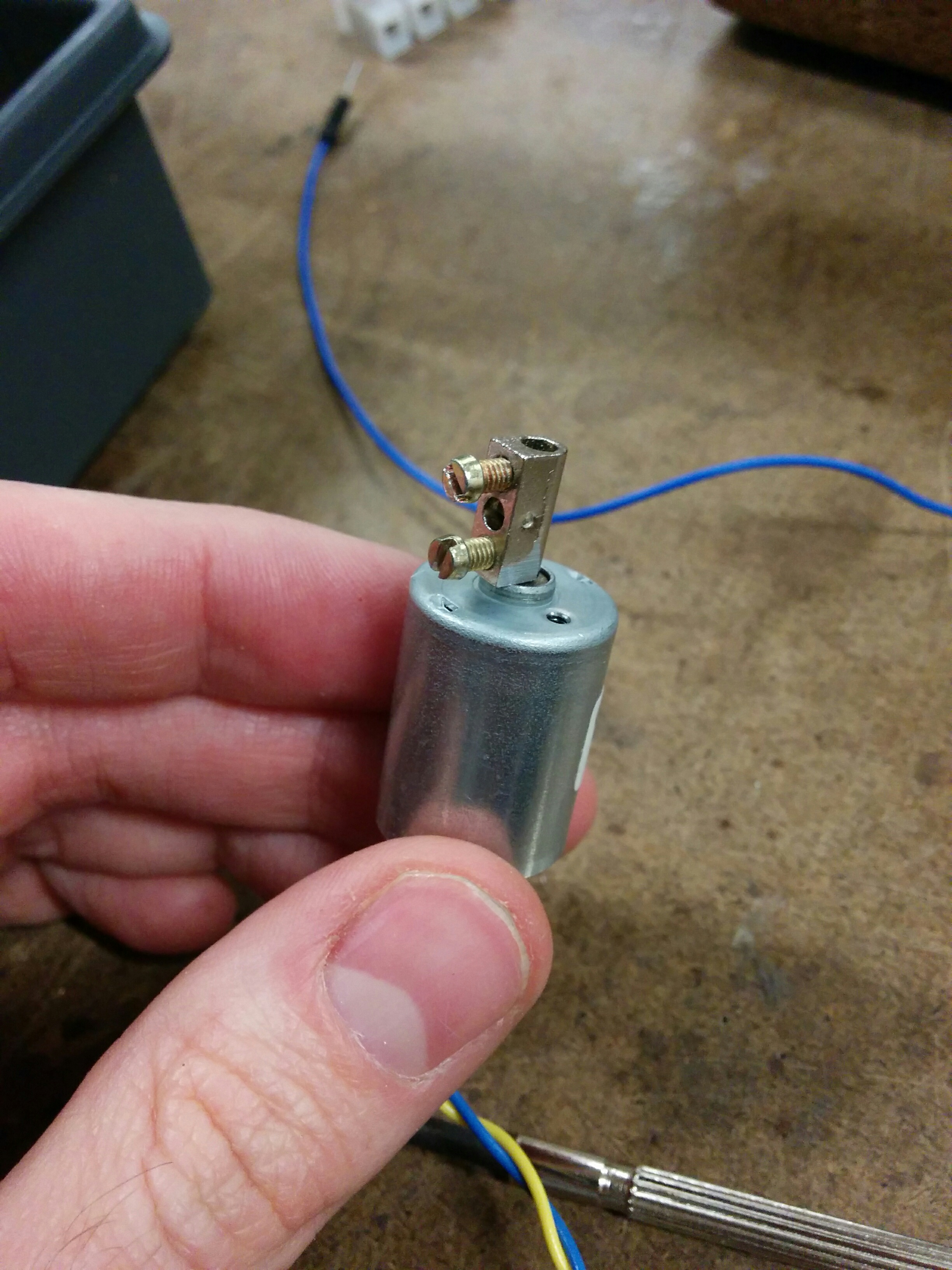
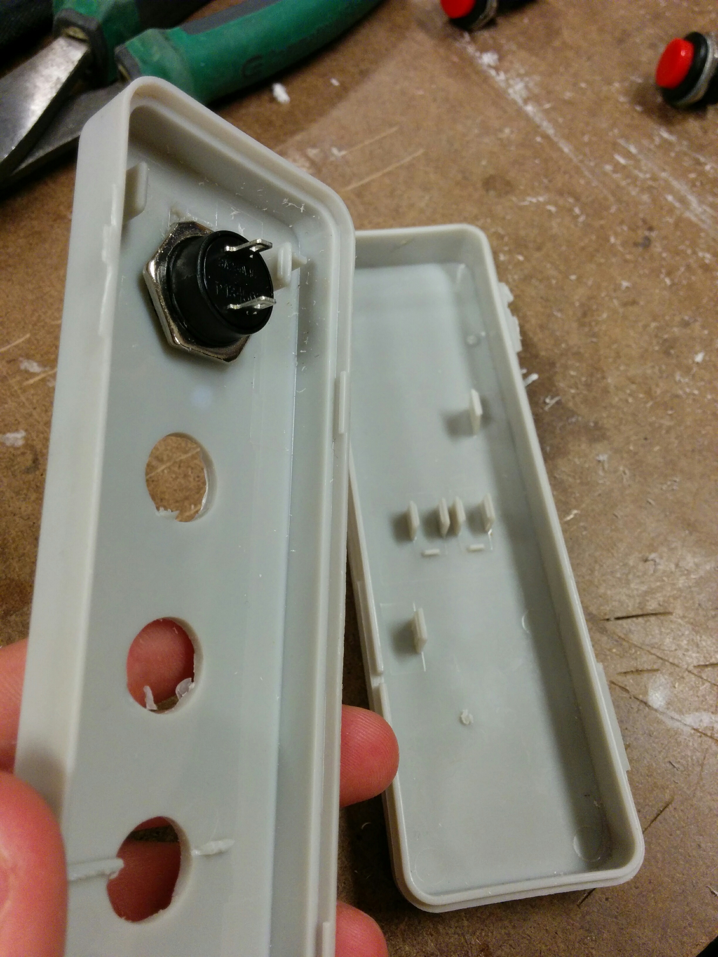
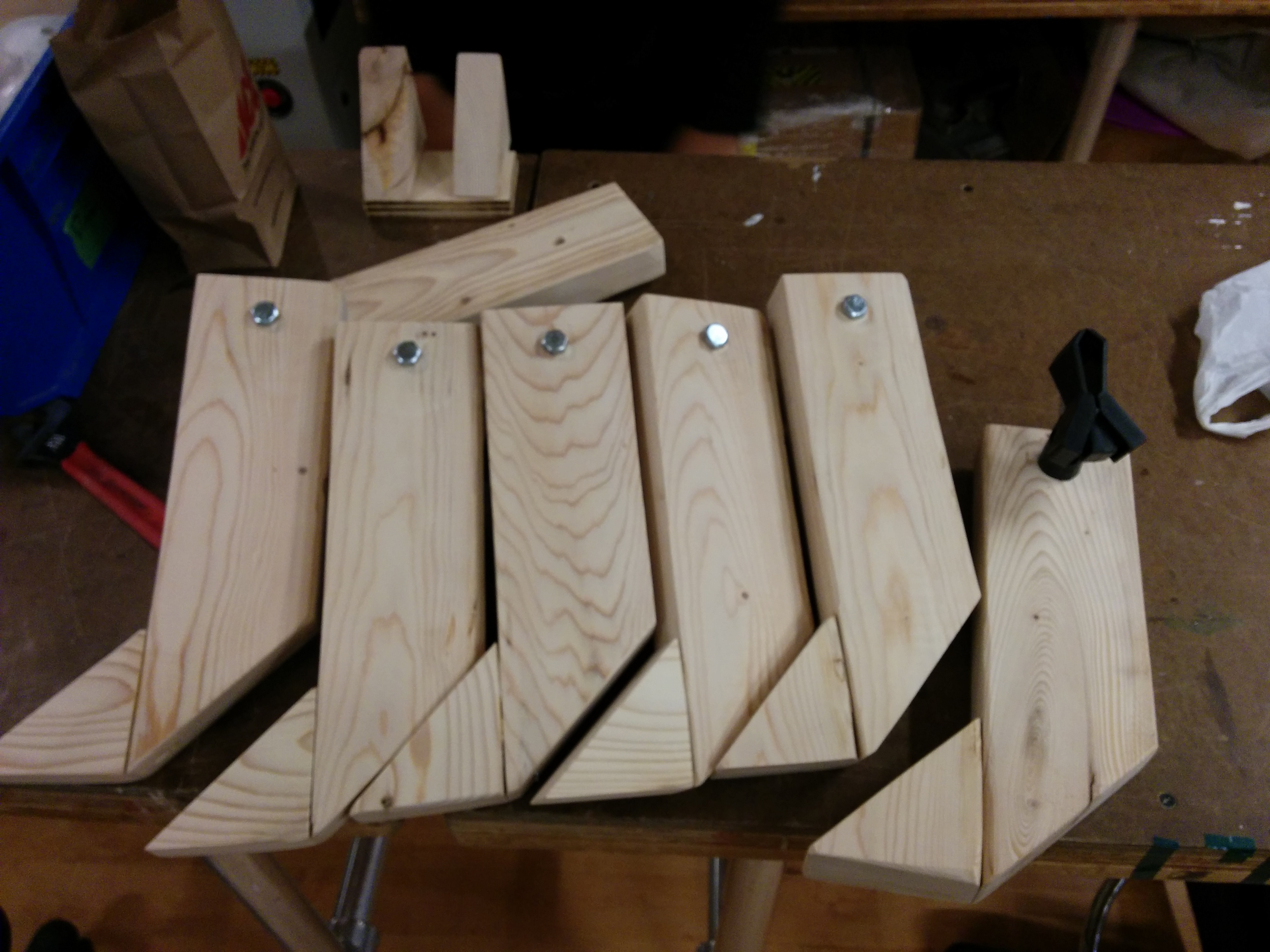
However, learning my lesson, I got into a groove and took out multiple shaft couplers. They fit on my DC motor nicely.

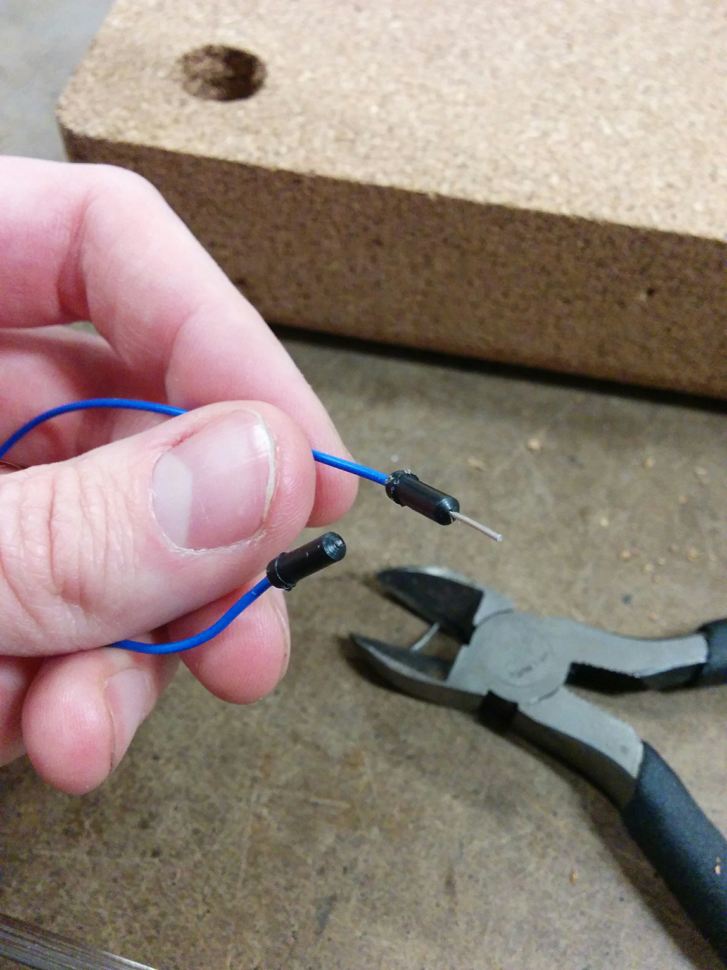
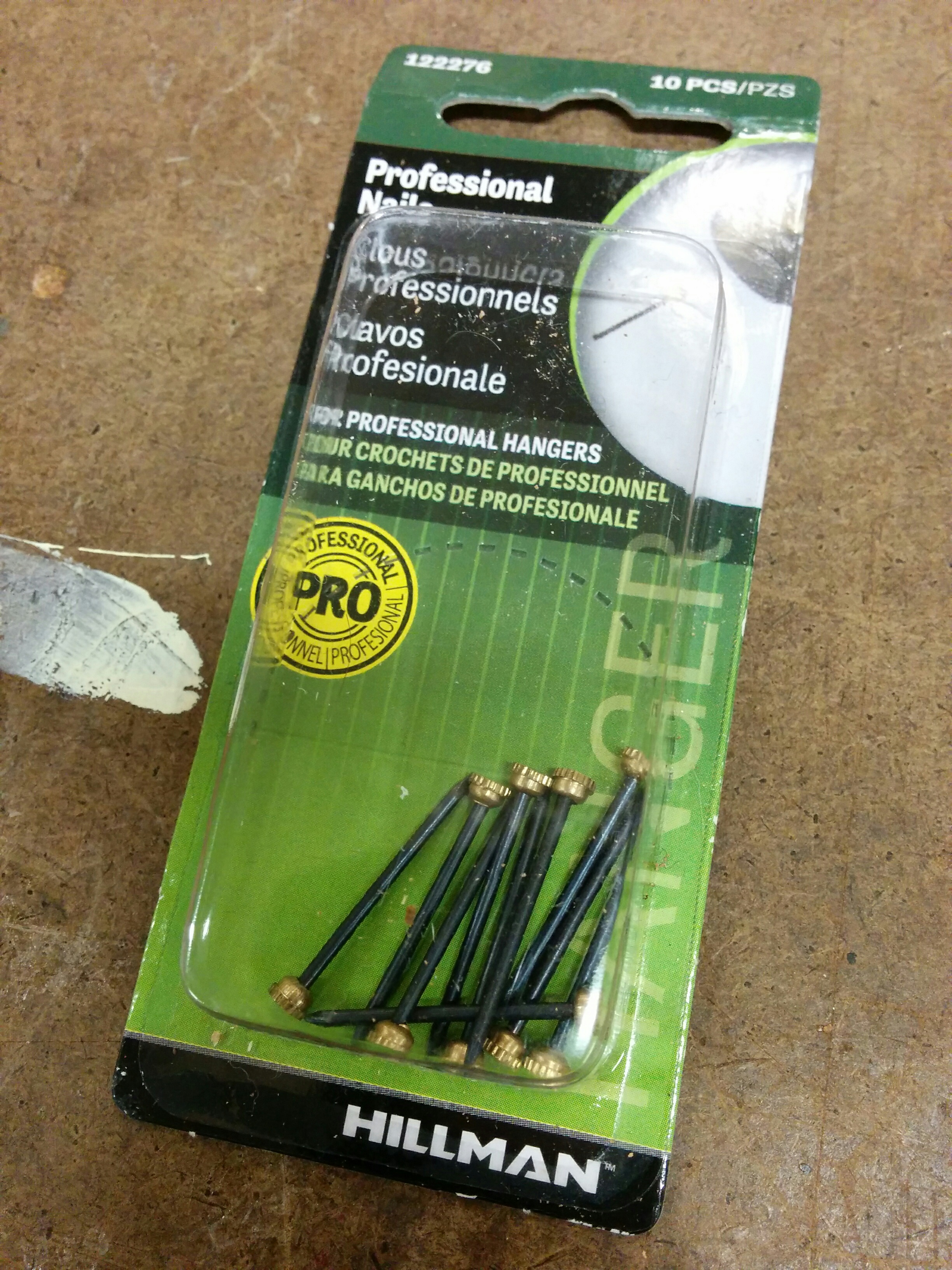
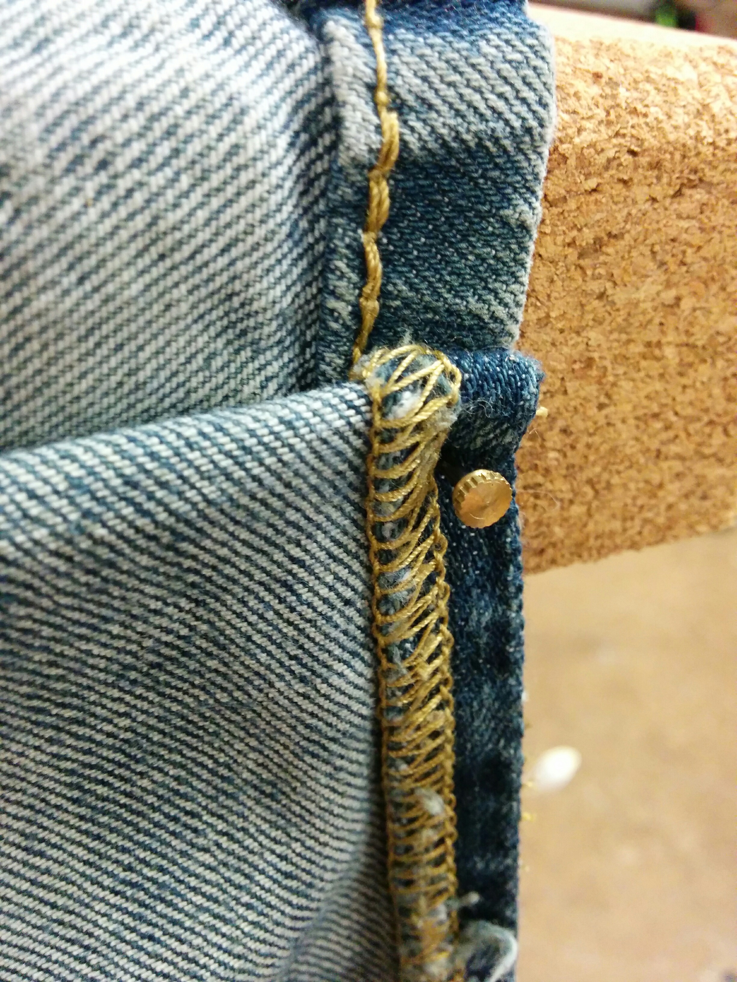
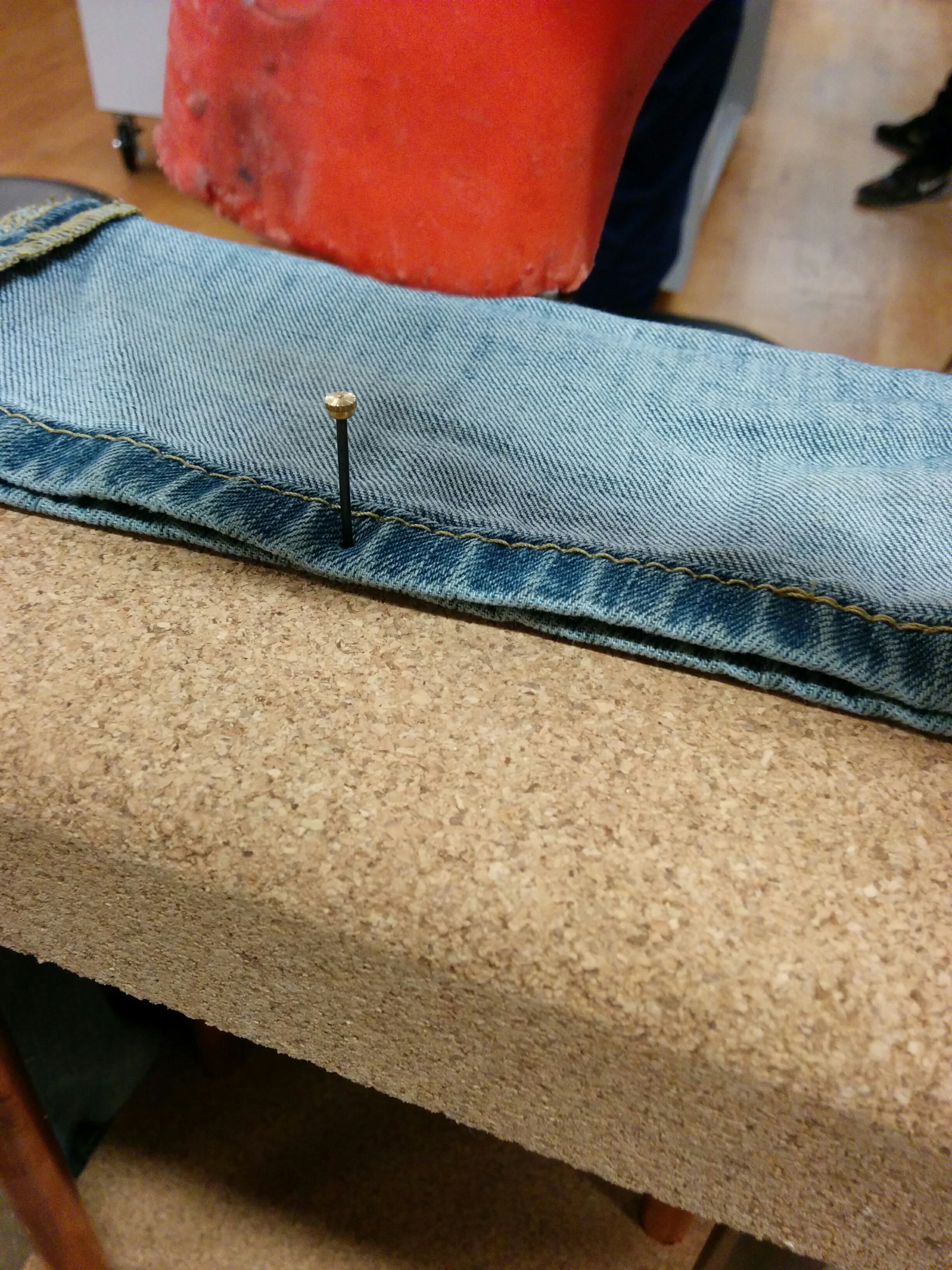
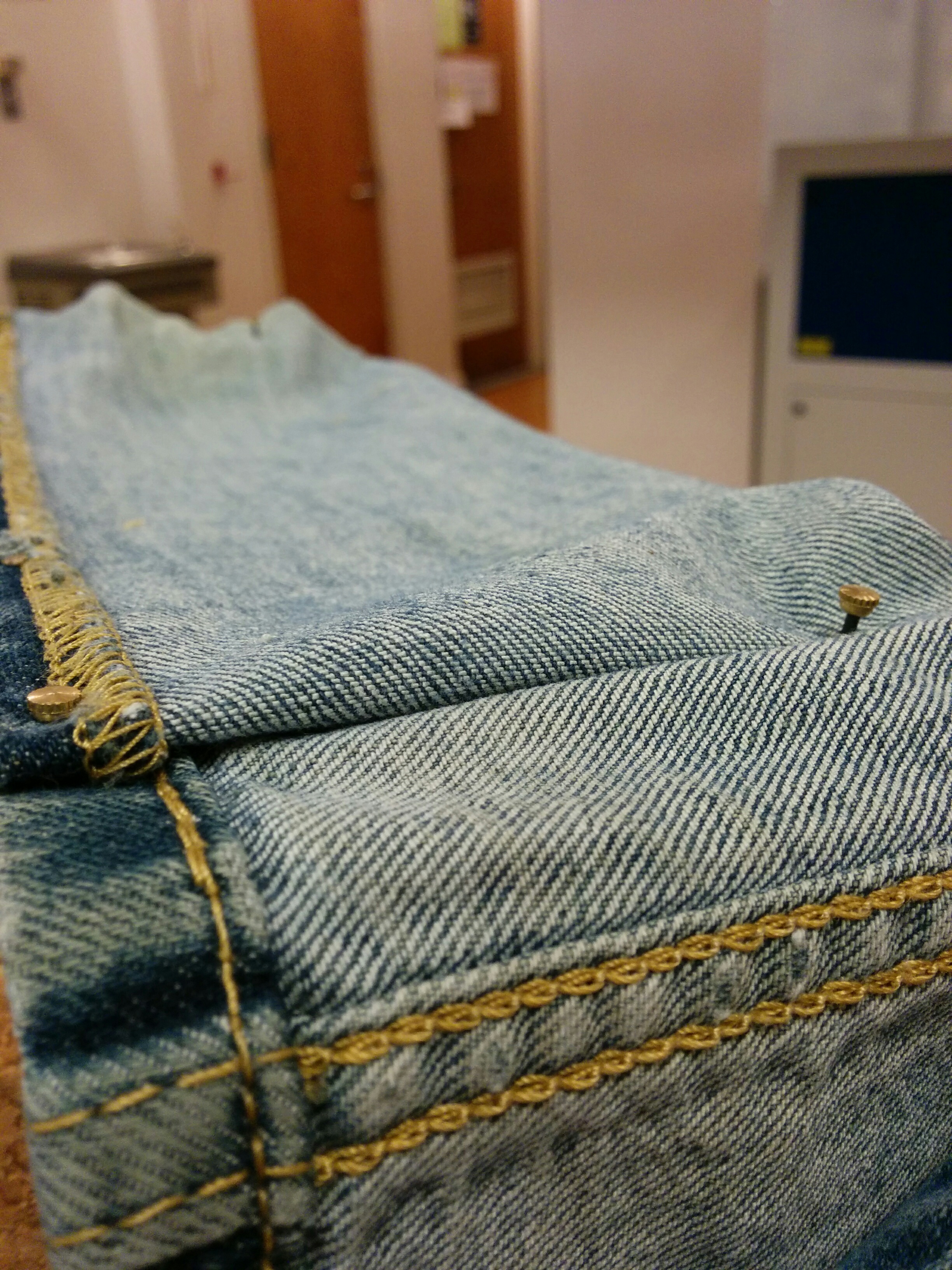
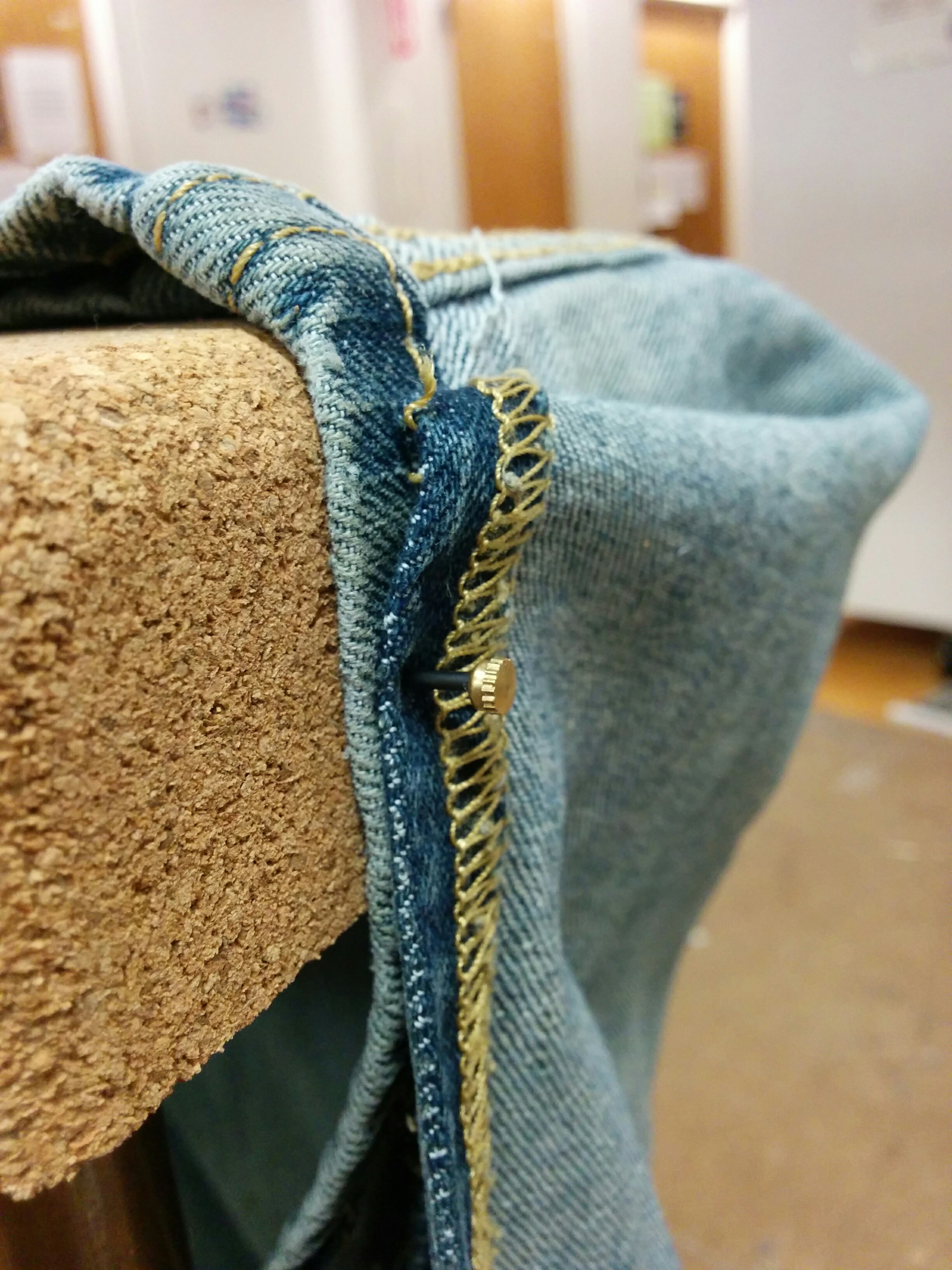
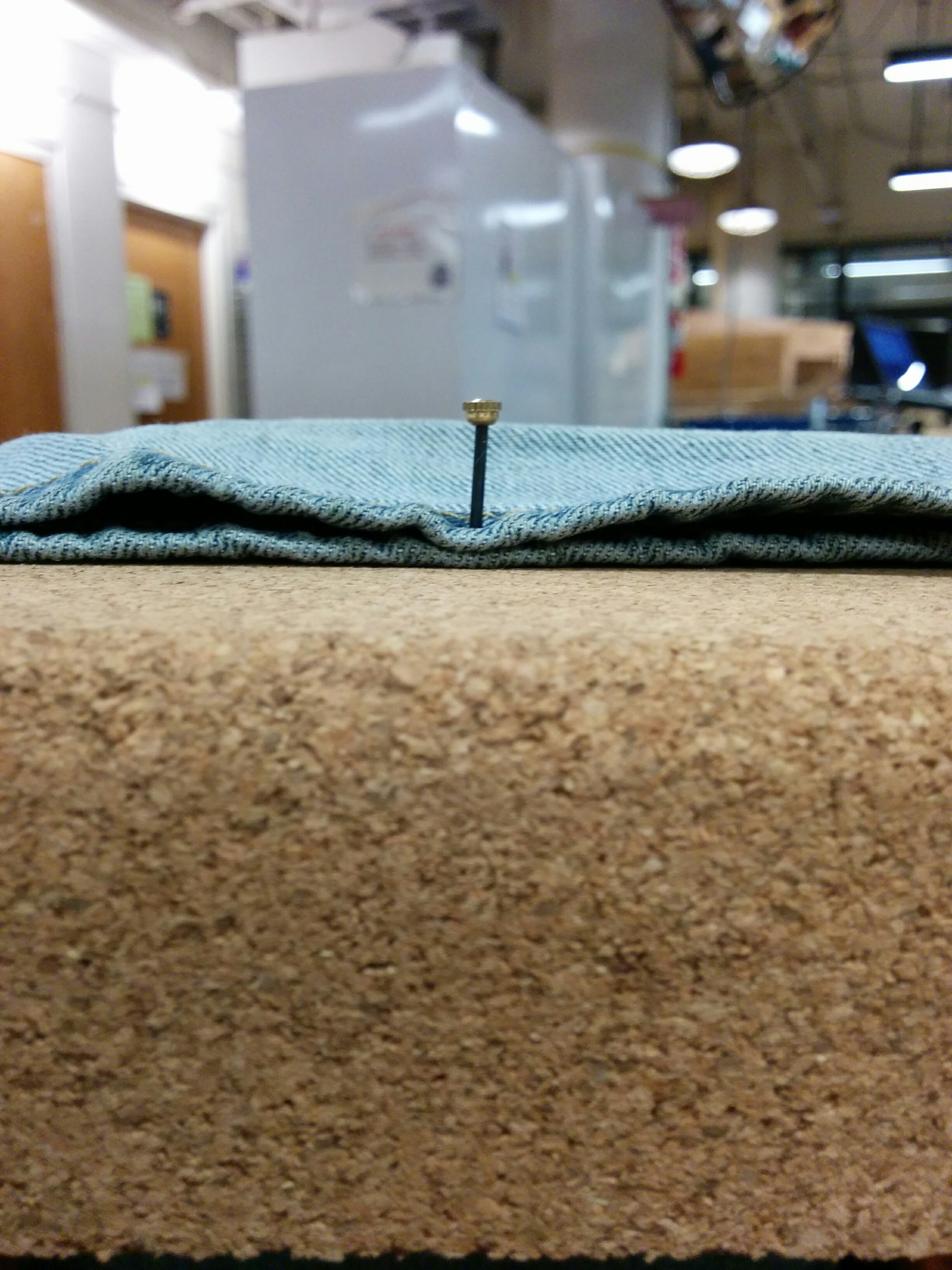
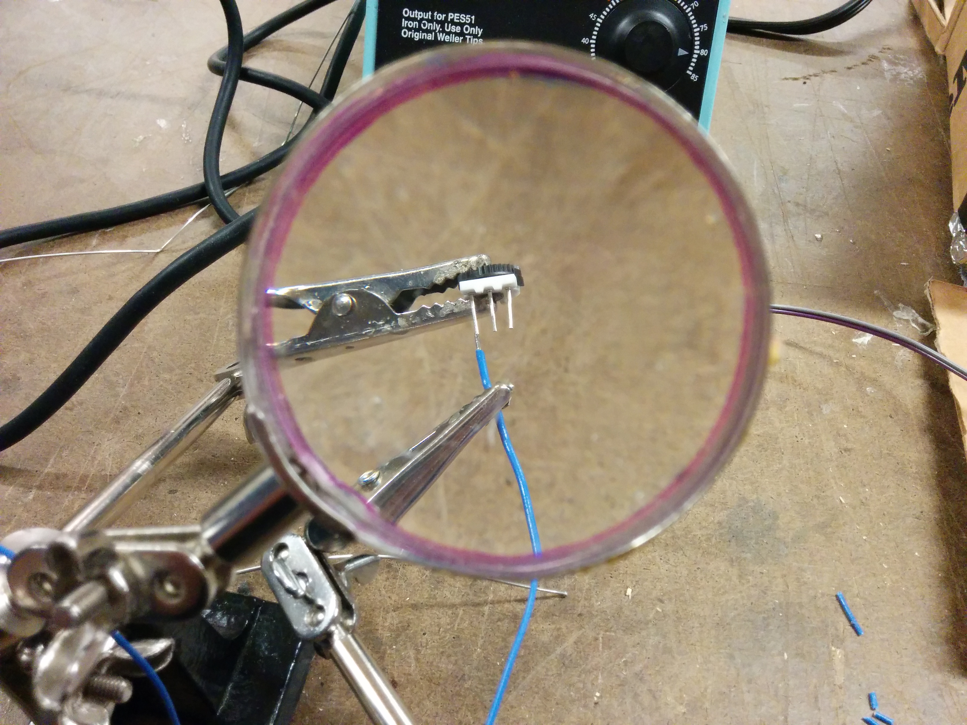
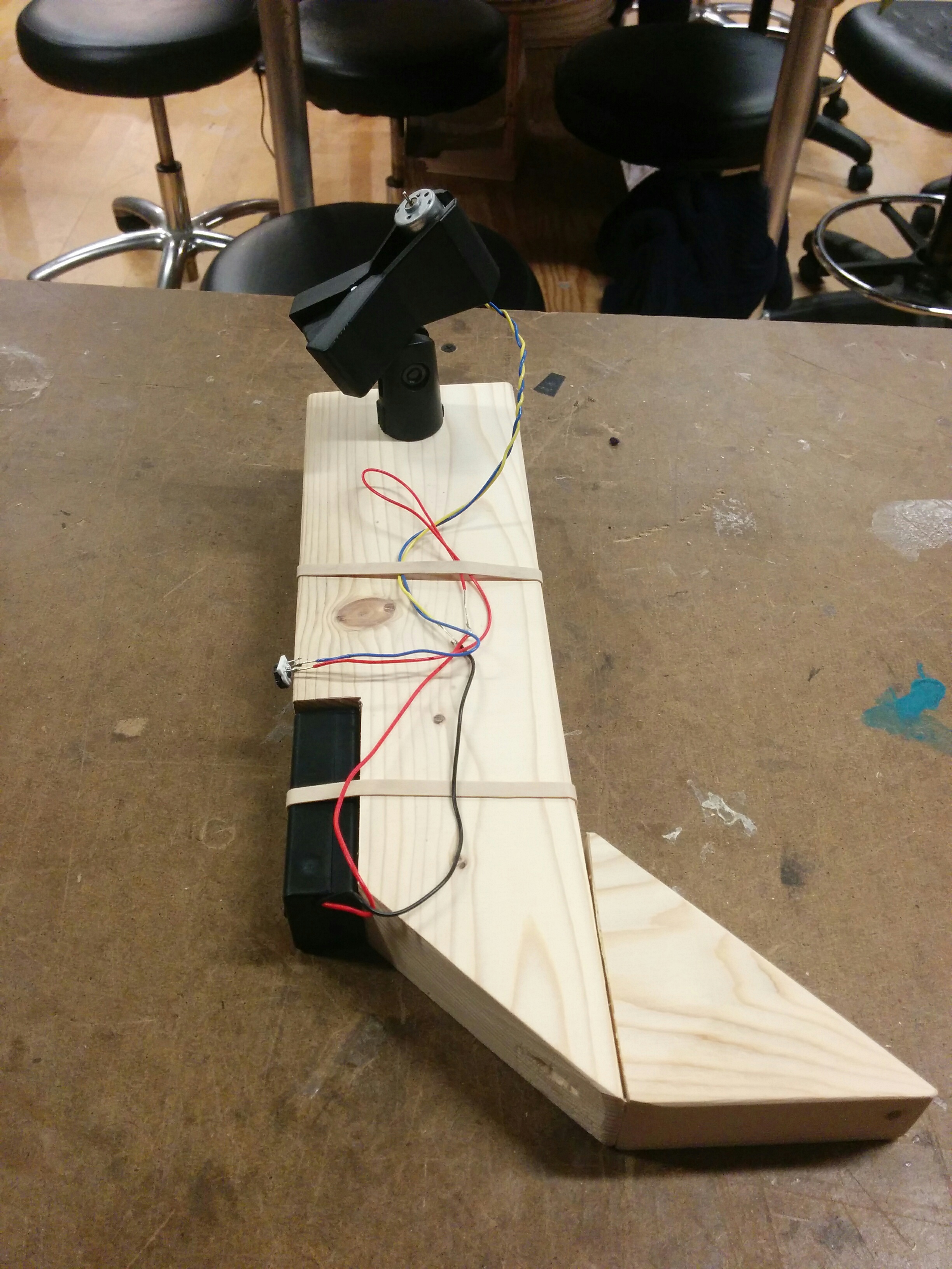
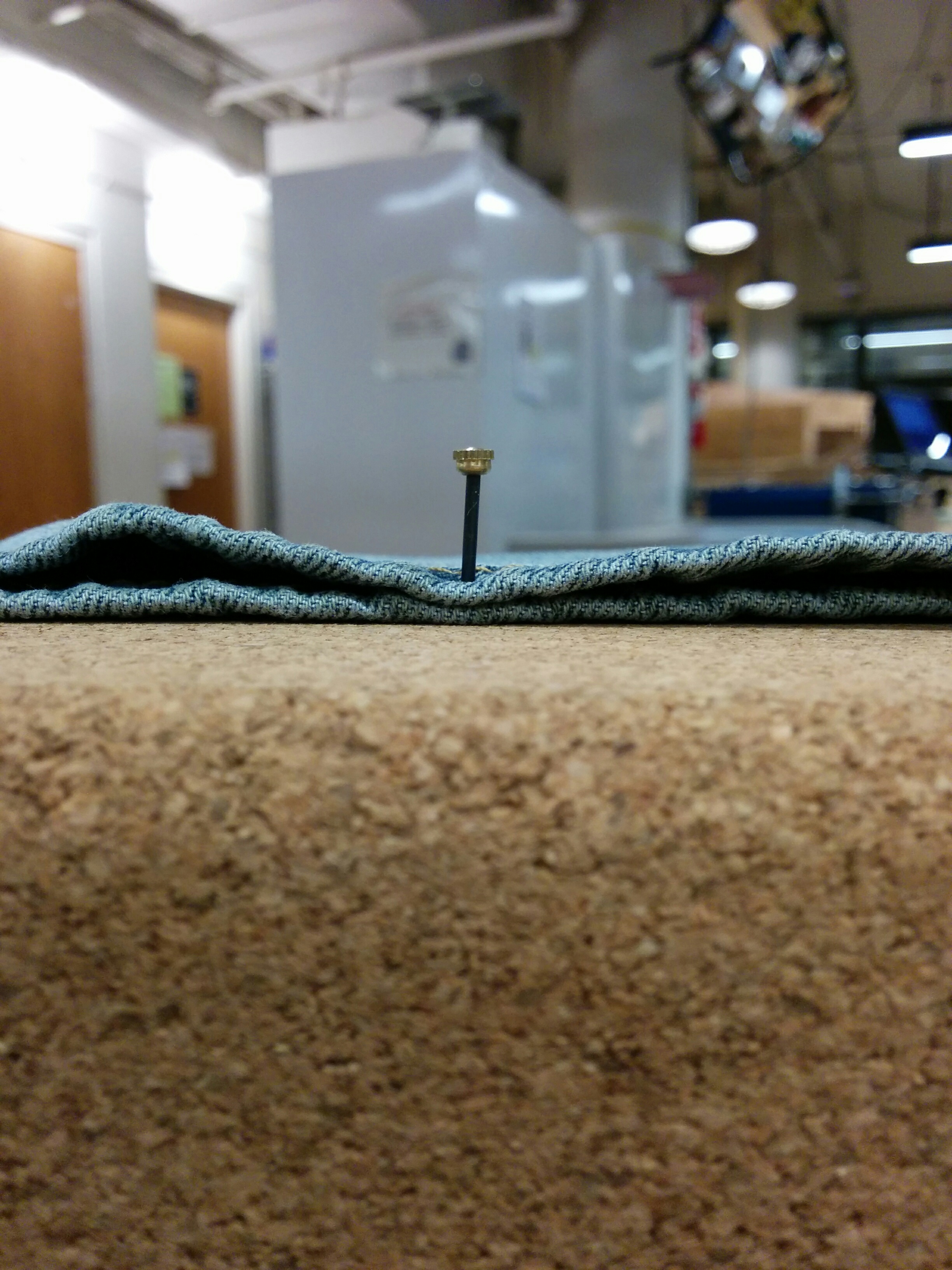
I wanted to have some kind of soft, flexible percussive element screwed in securely to the other side of the shaft coupler. I clipped the metal pin to one side of a jumper cable and then secured the other end into the coupler.

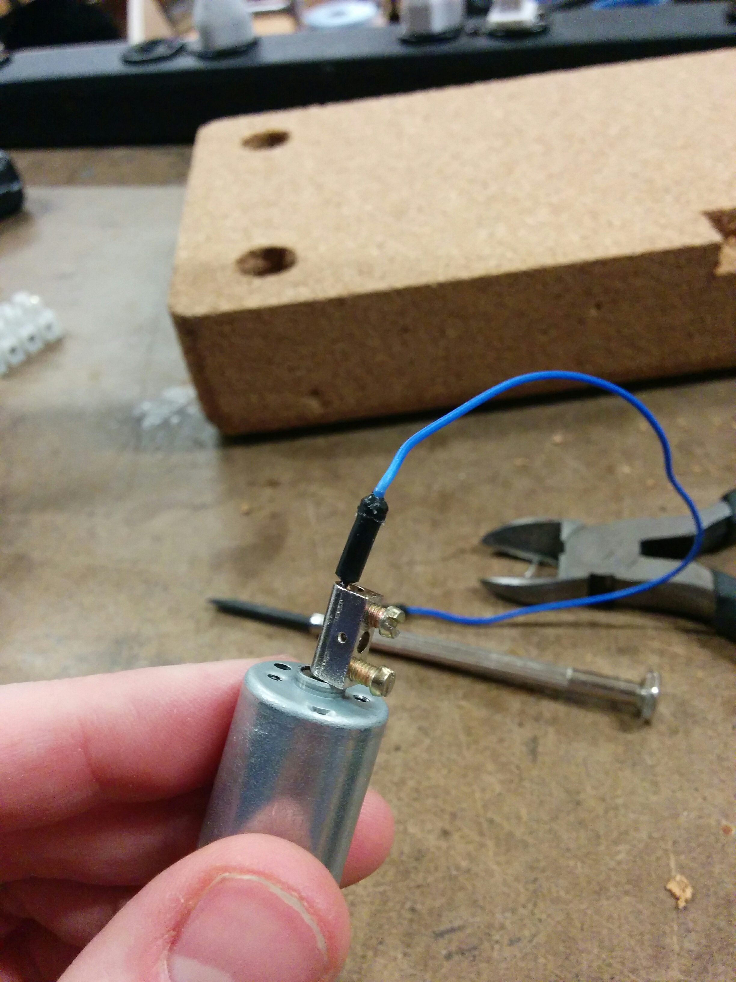
Then I turned on the motor:

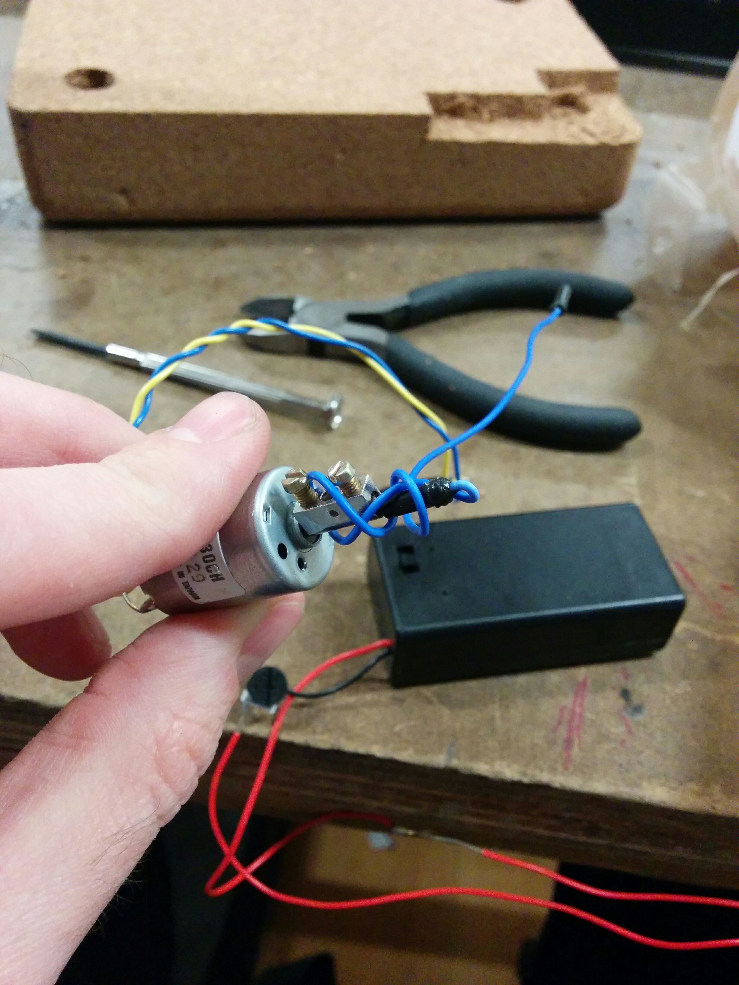
And it immediately twisted up on itself. I thought maybe it was spinning too fast, so I tried to slow down the speed, straightened it out, and then hit it again.

It spun so fast that the plastic contact wore out in a second and sent the cable flying. Not the type of percussive effect I originally had in mind.

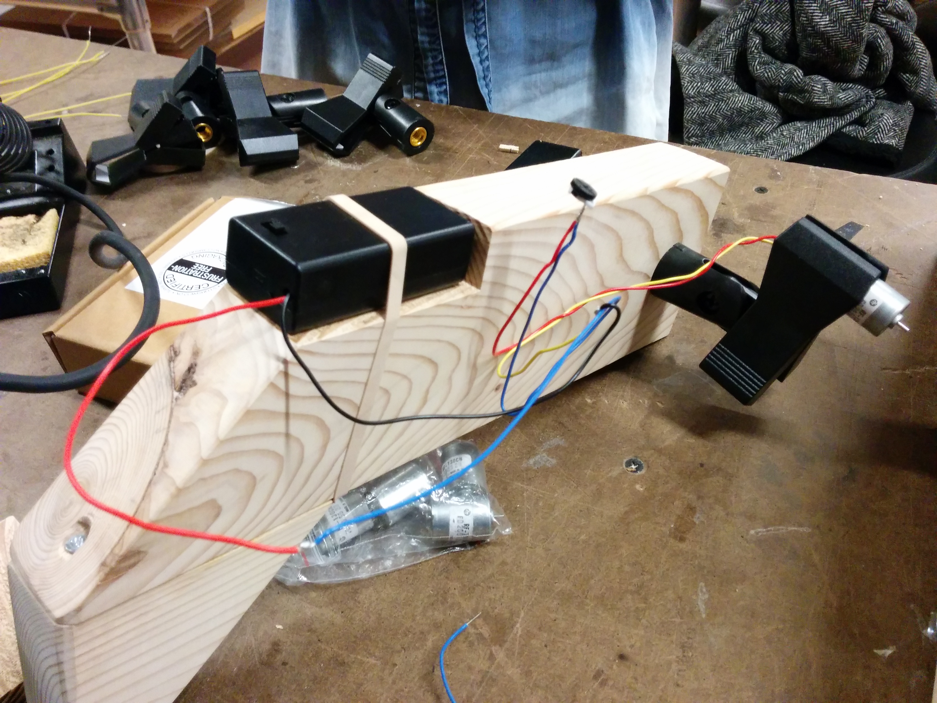
Maybe come back to that later, and moved on to mounting the motor.

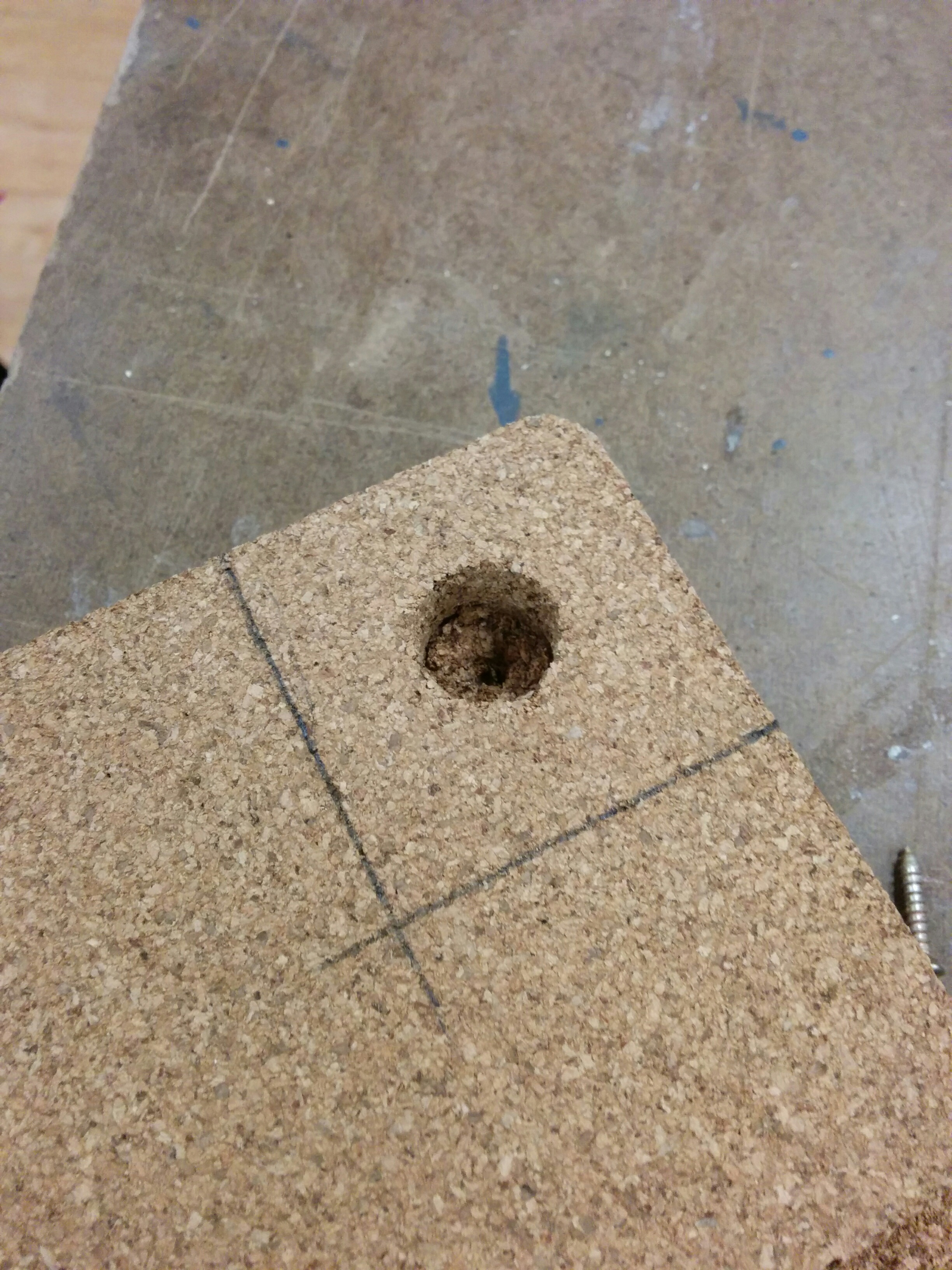
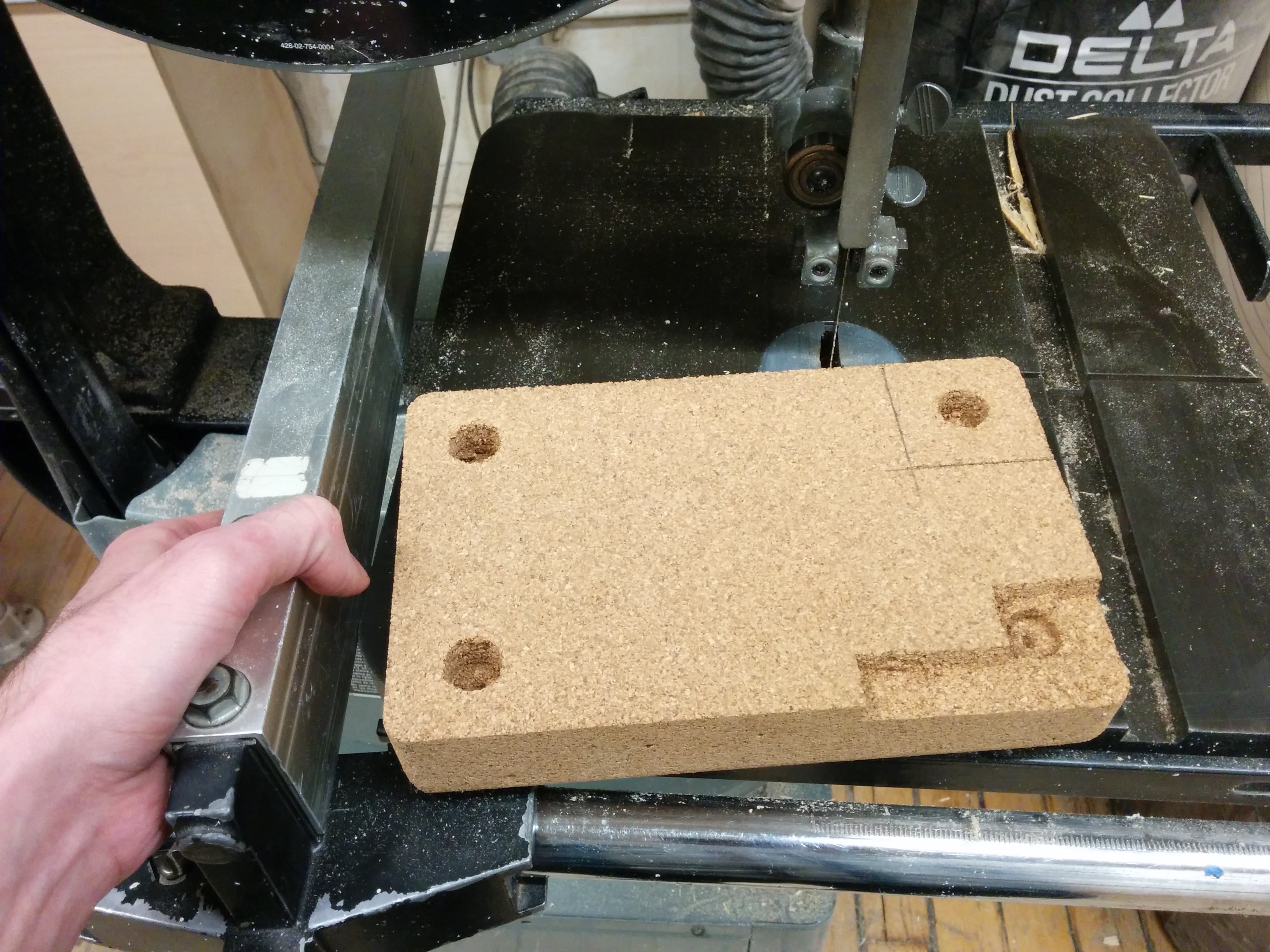
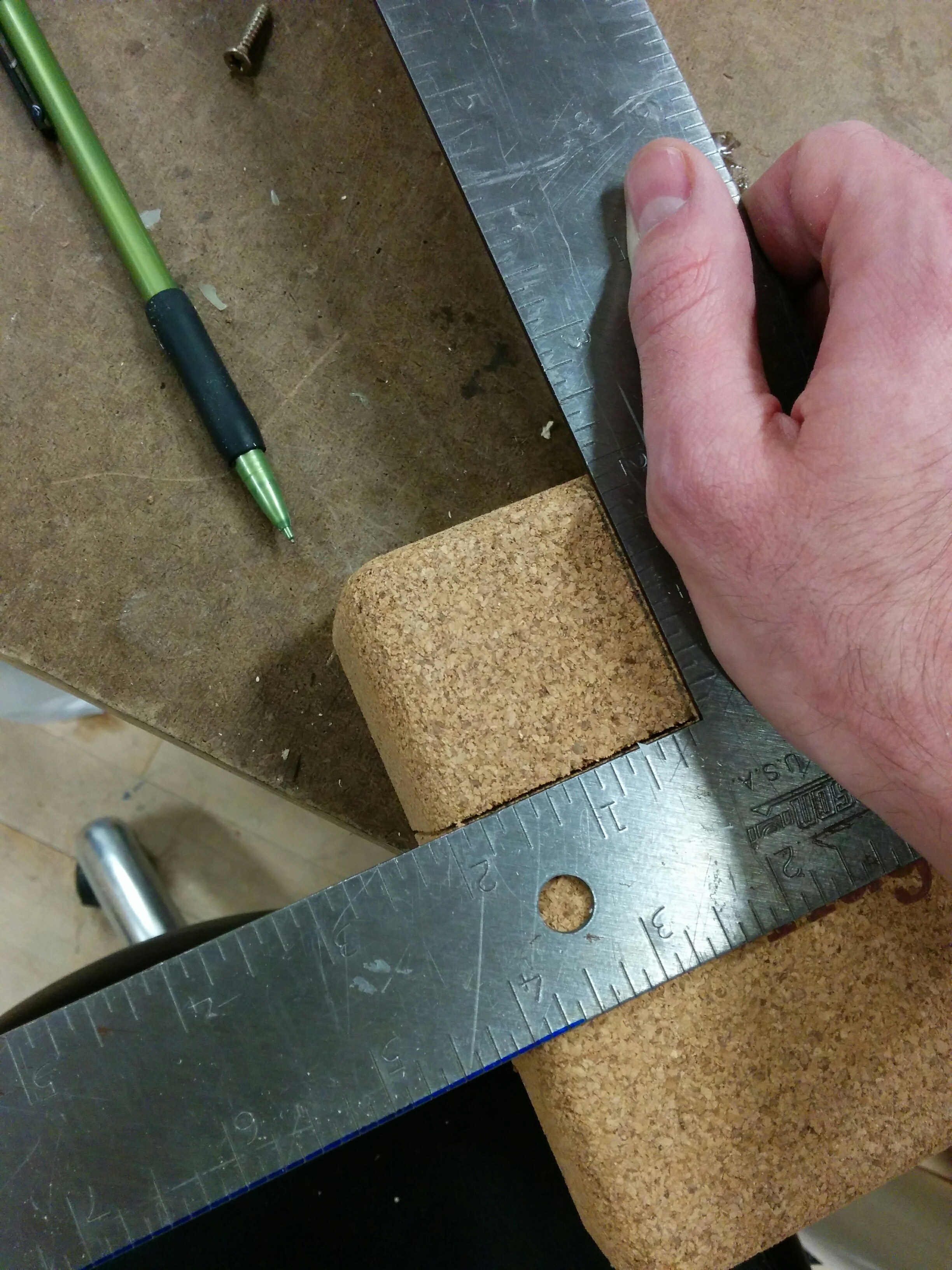
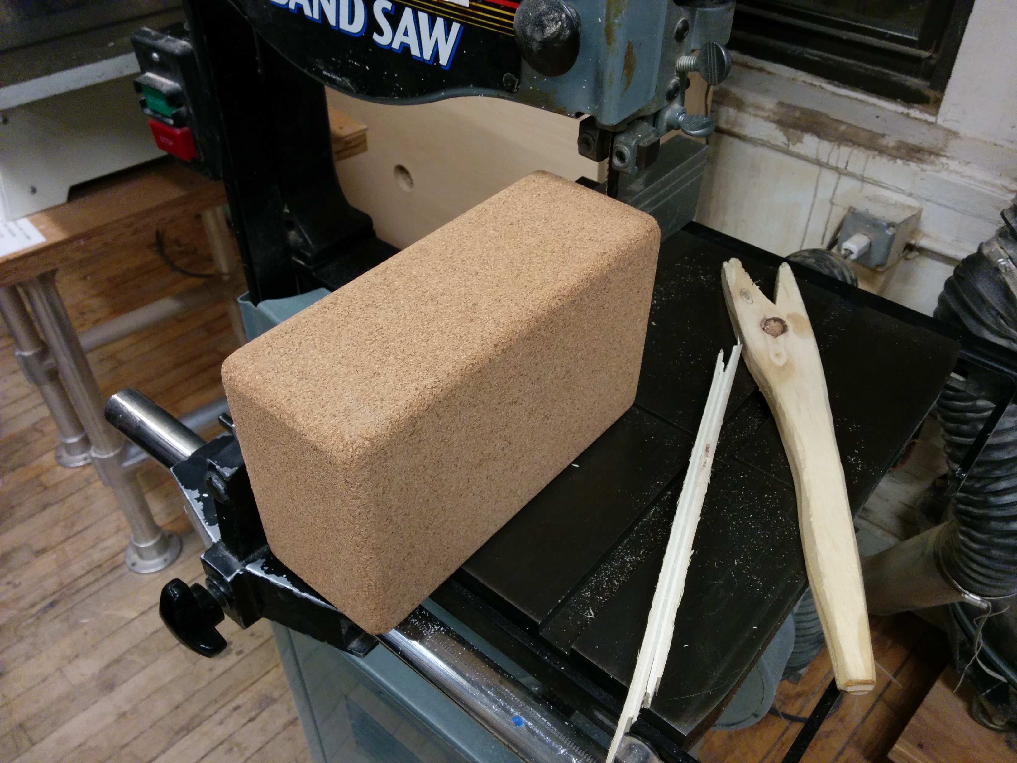
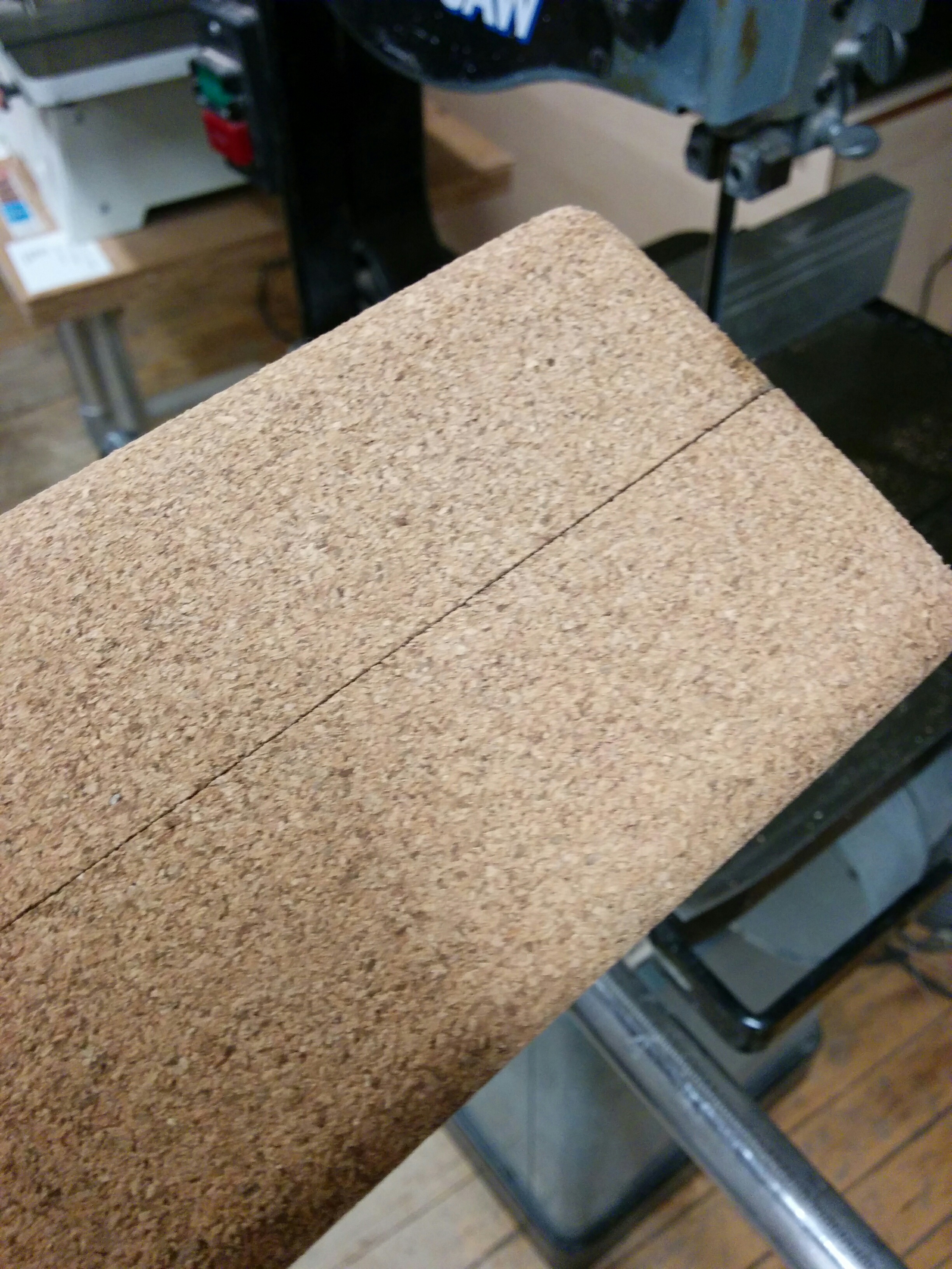
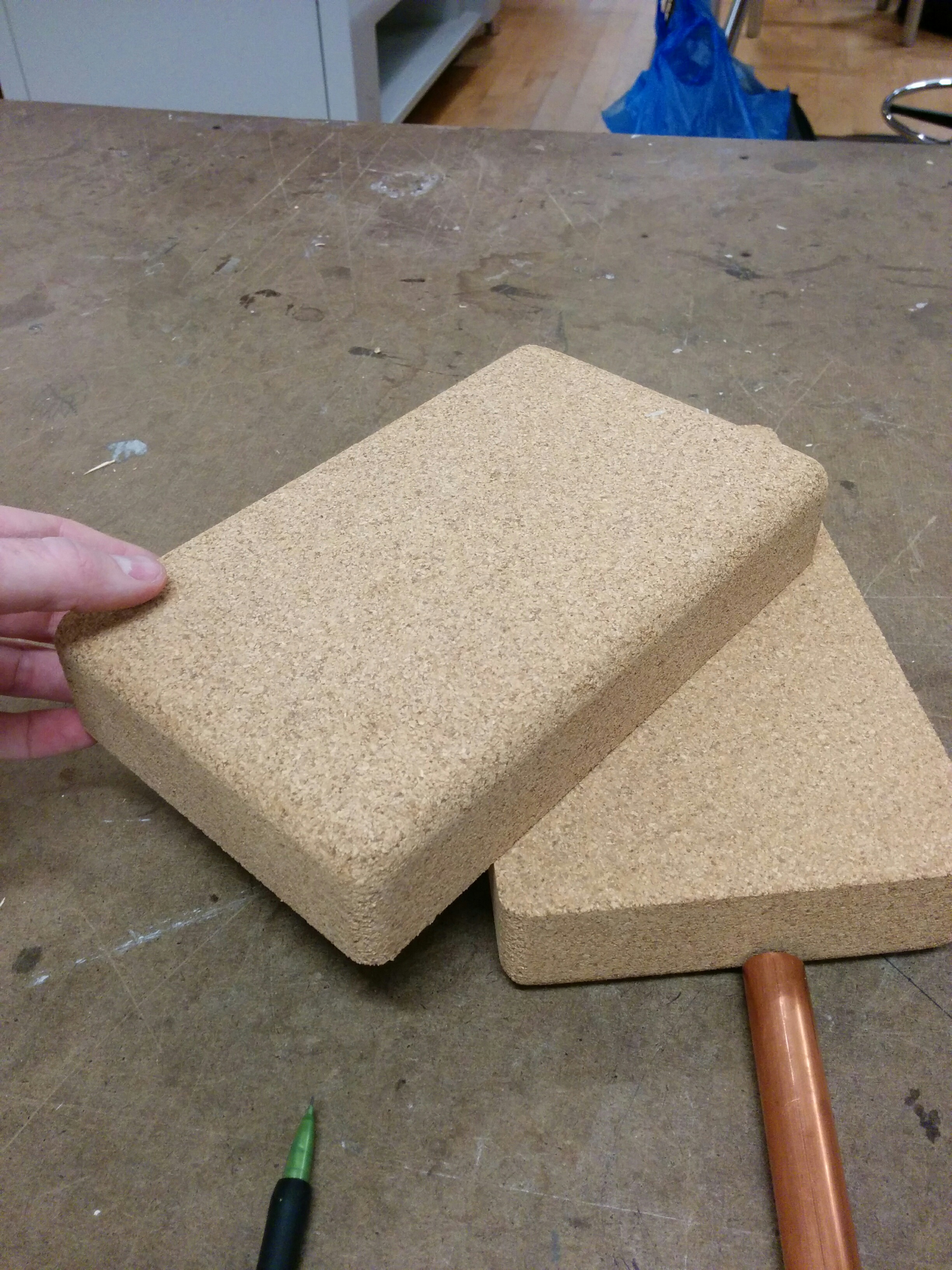
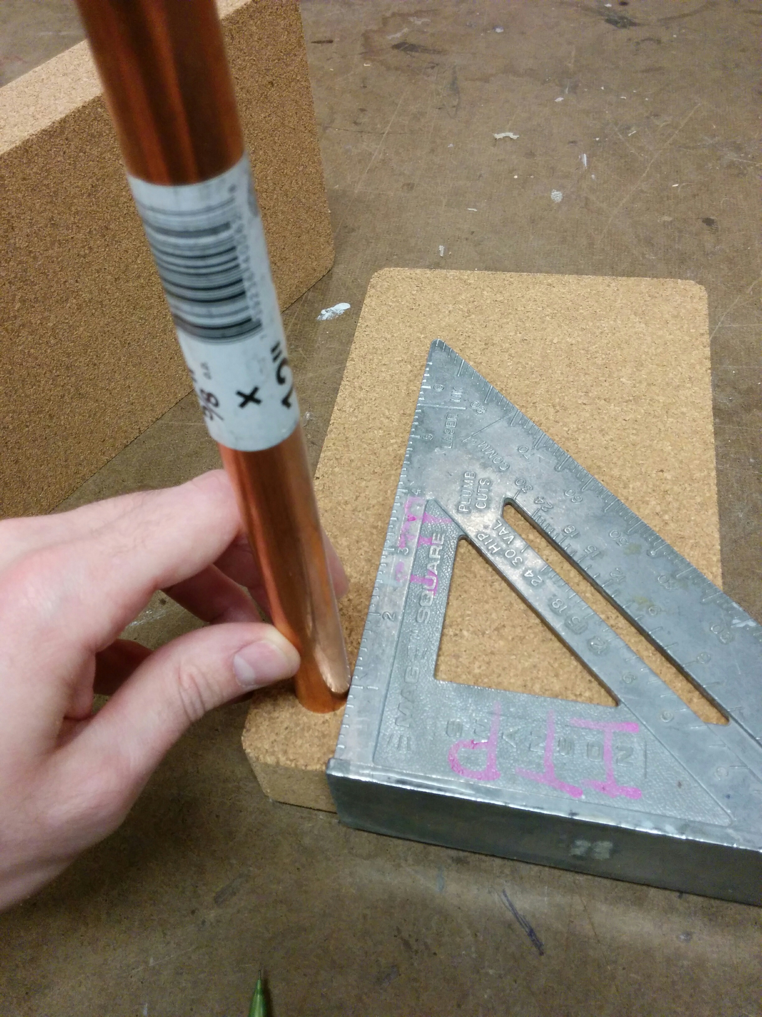
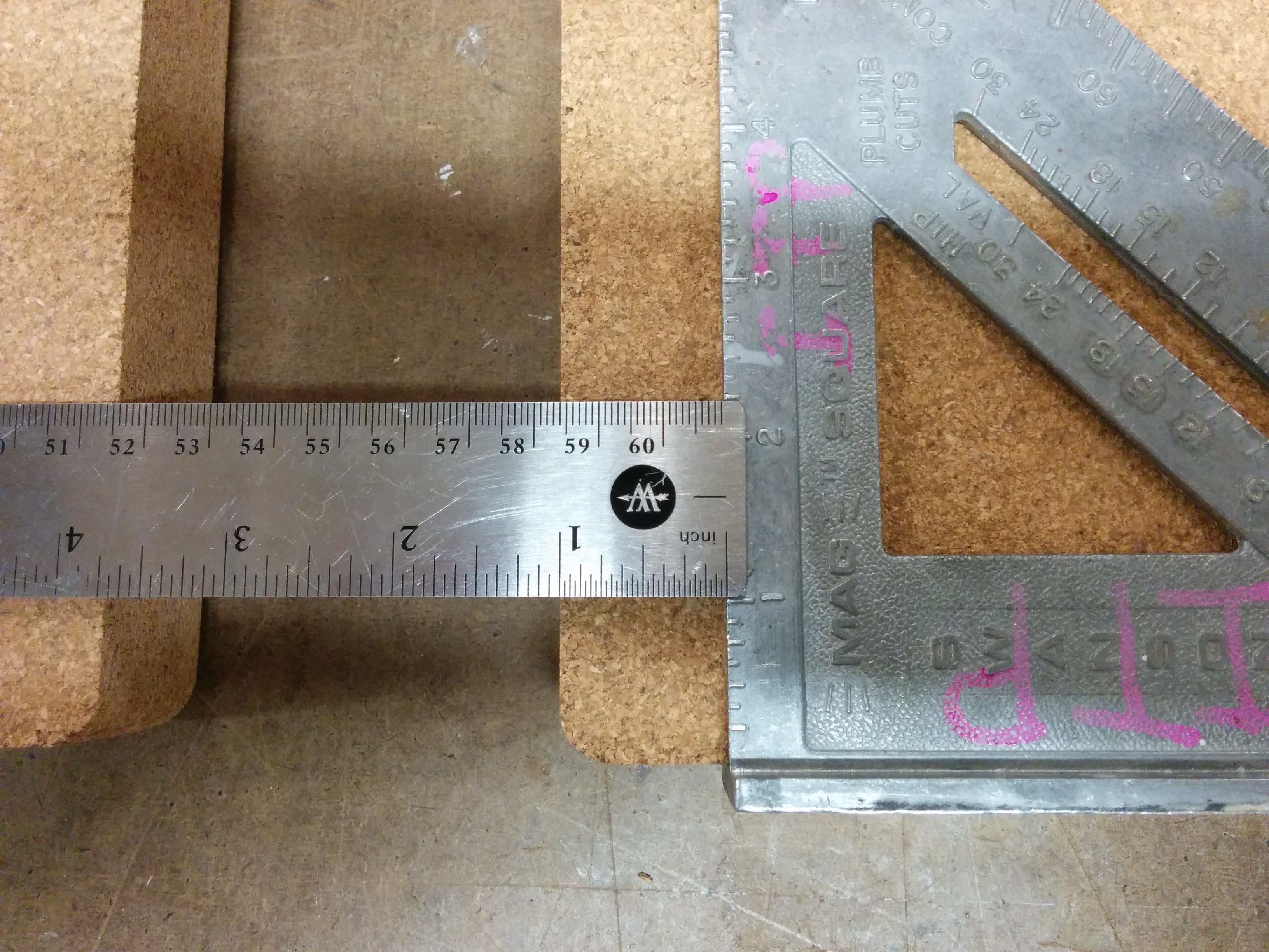
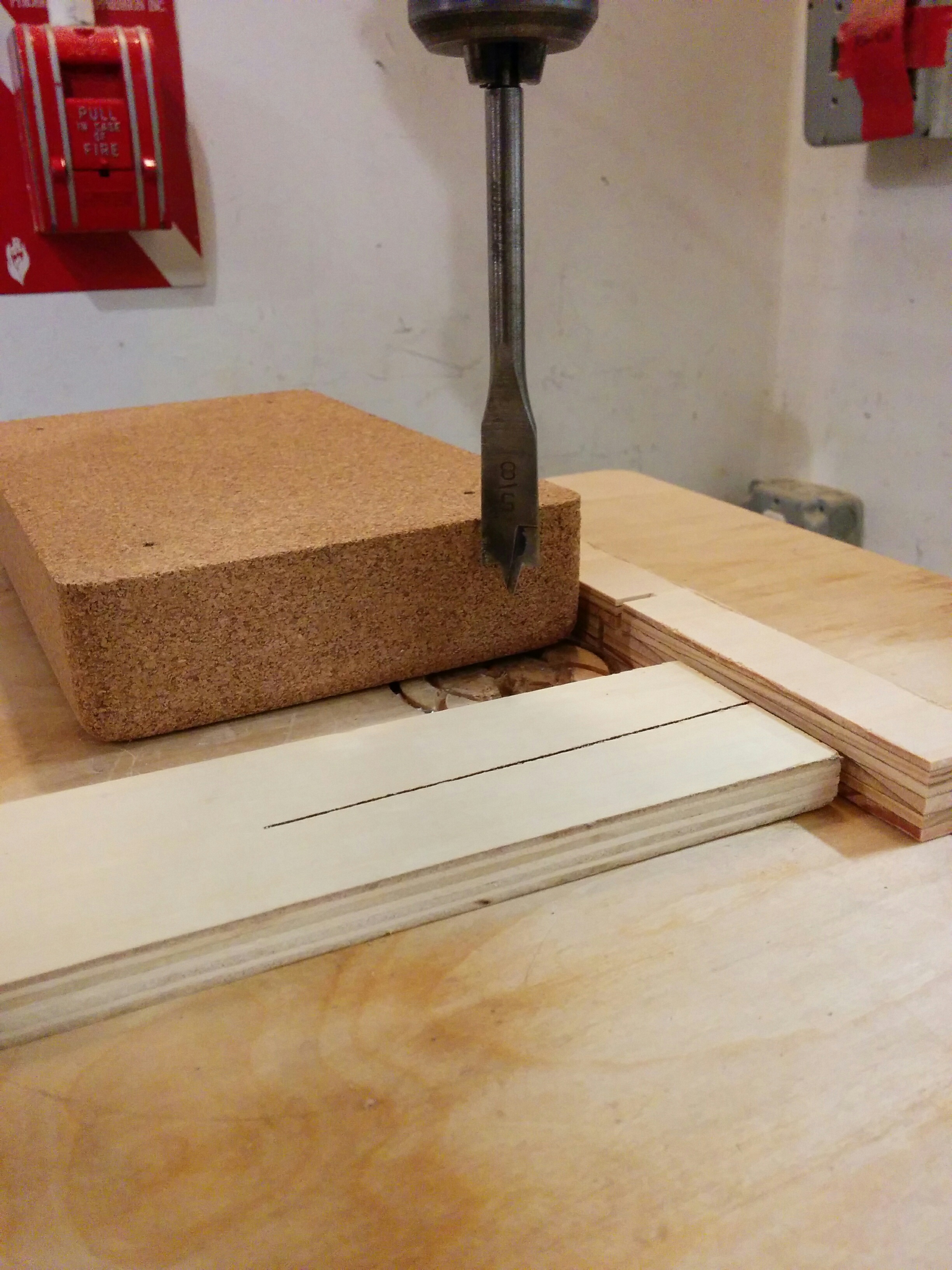
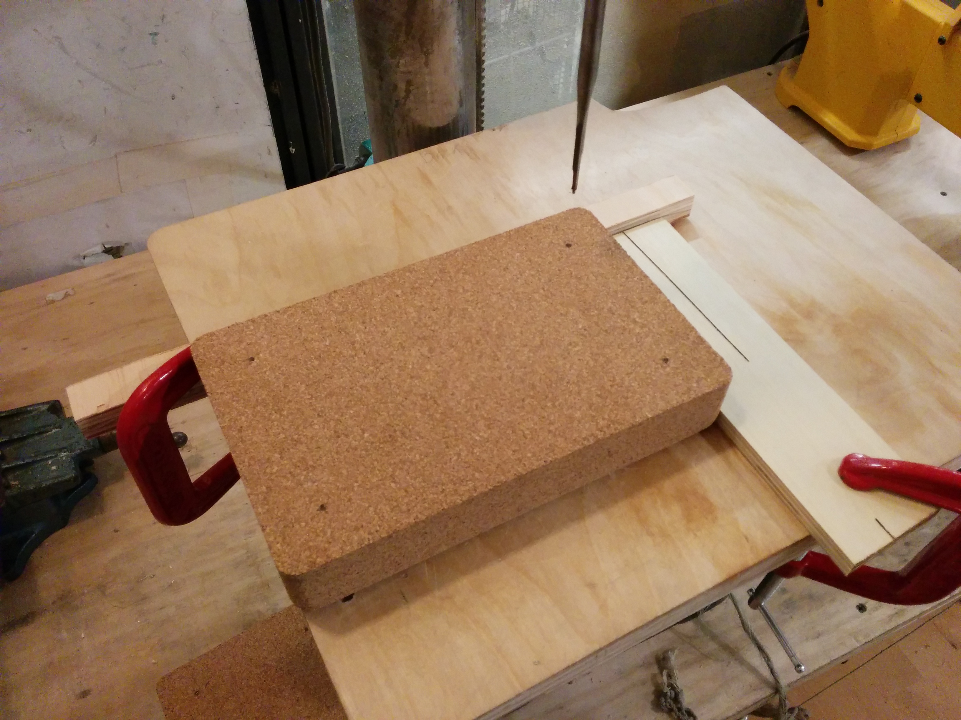
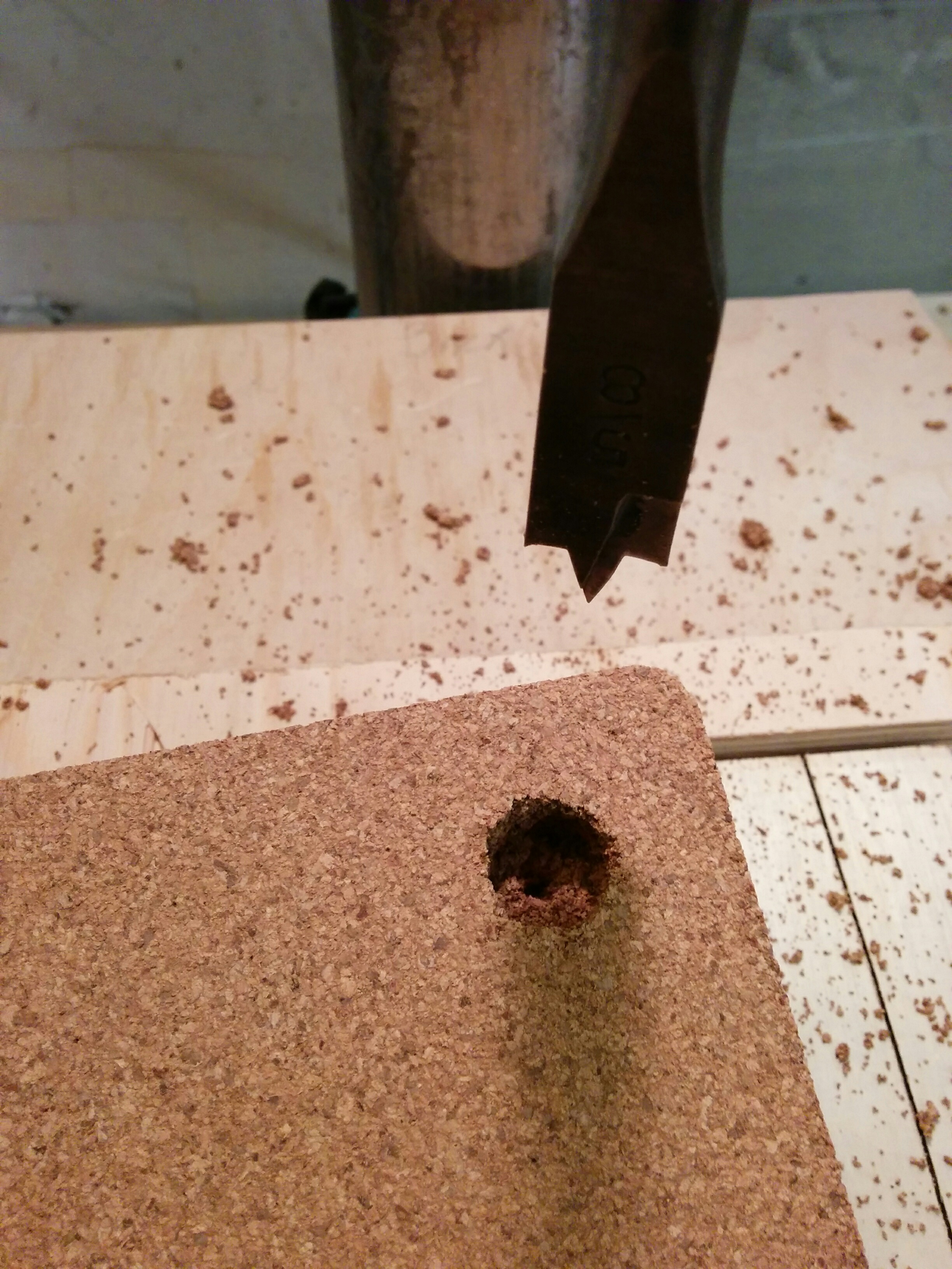
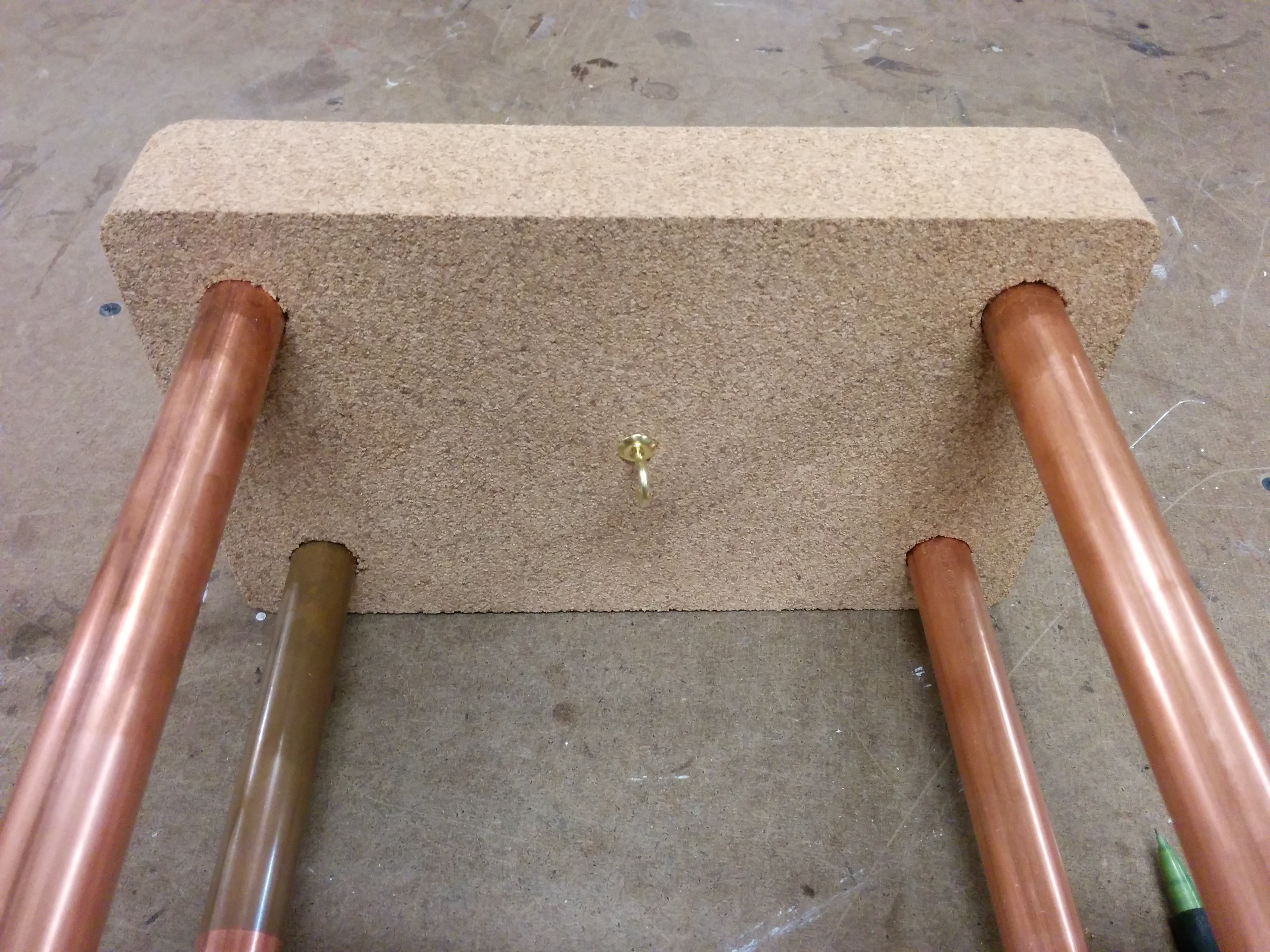
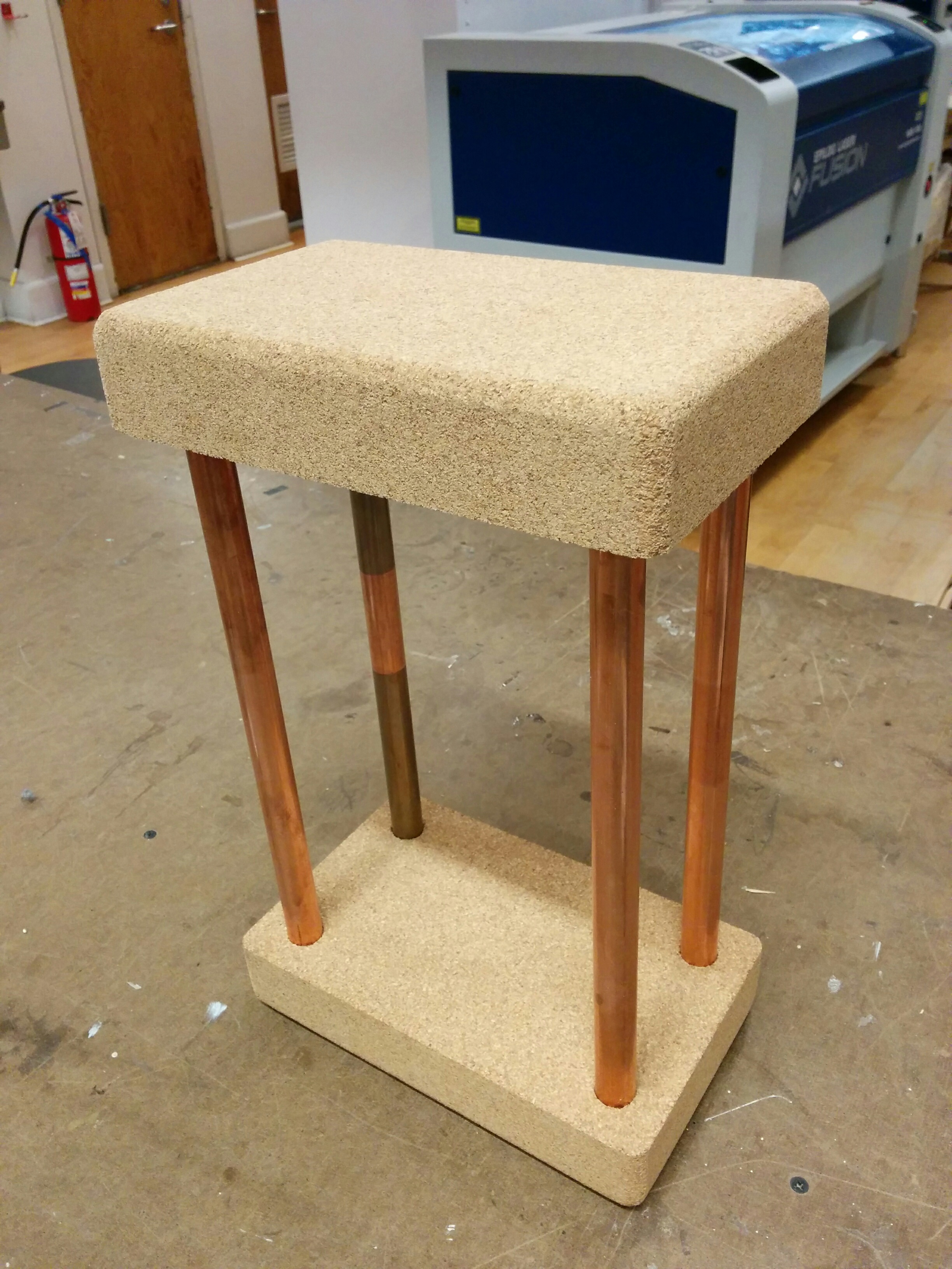
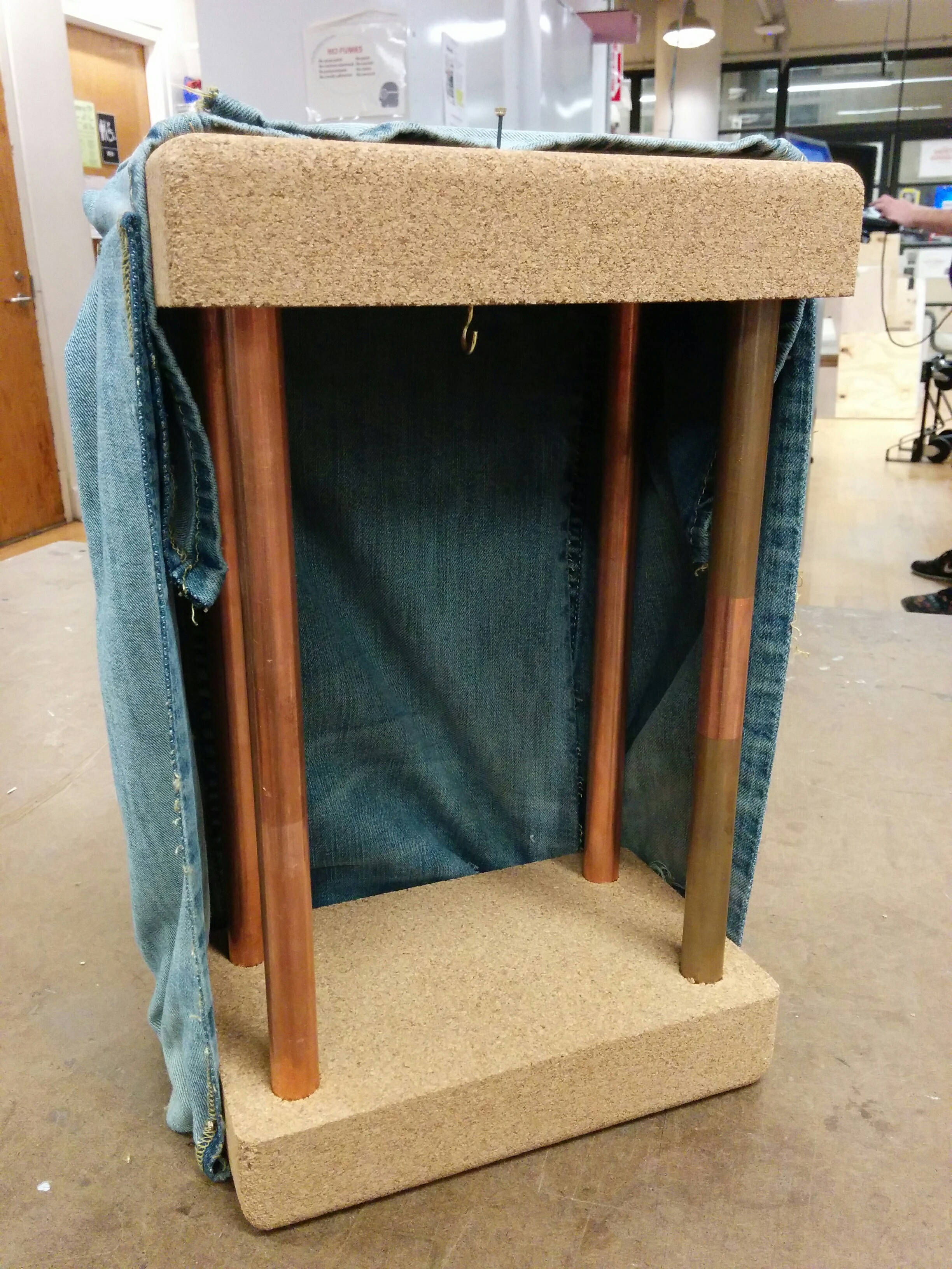
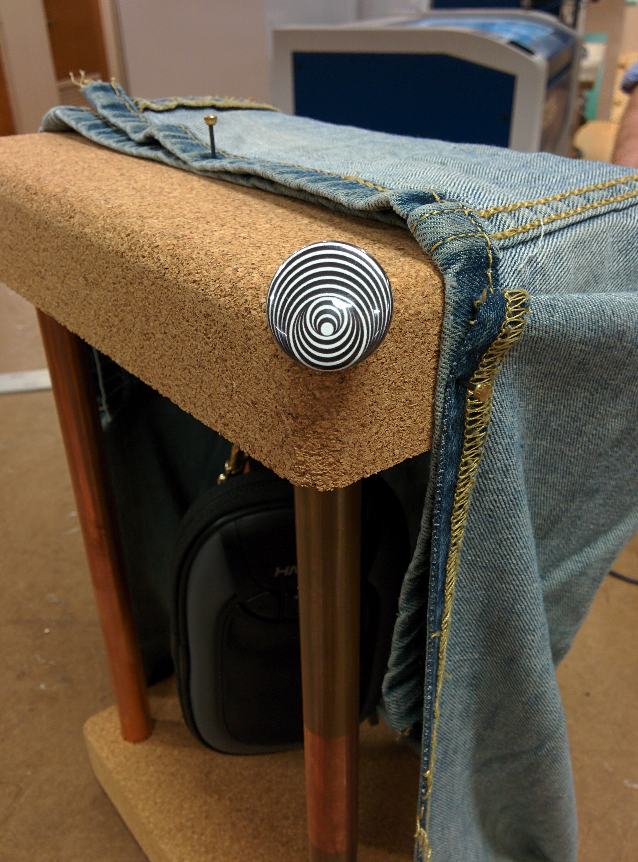
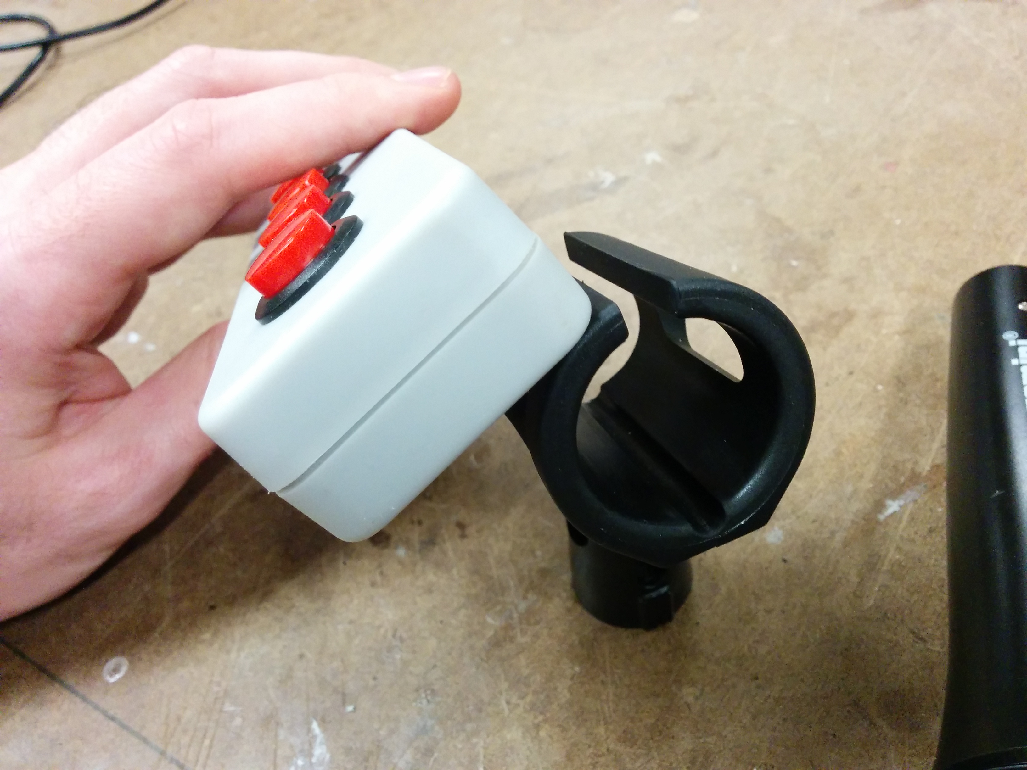
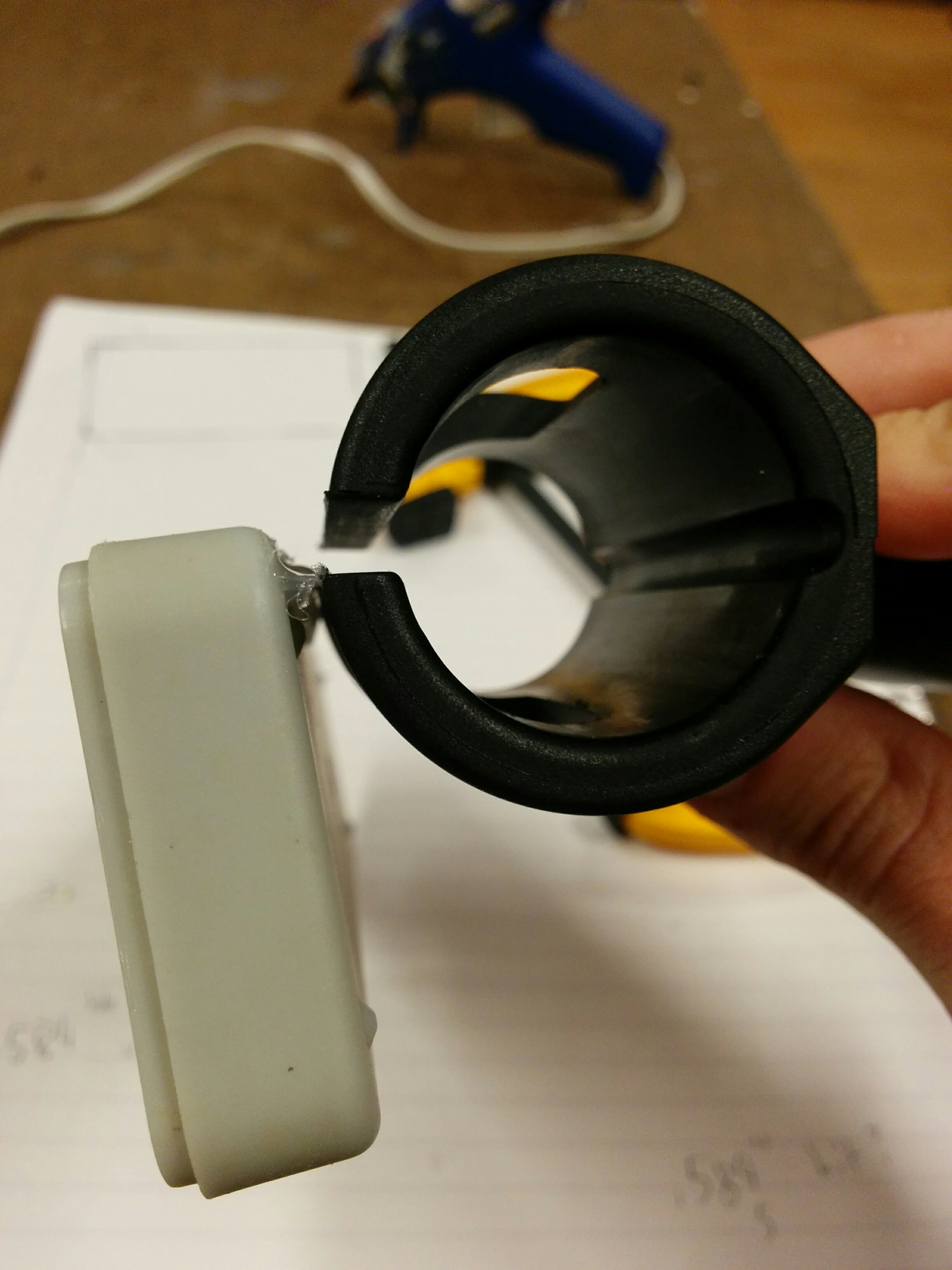
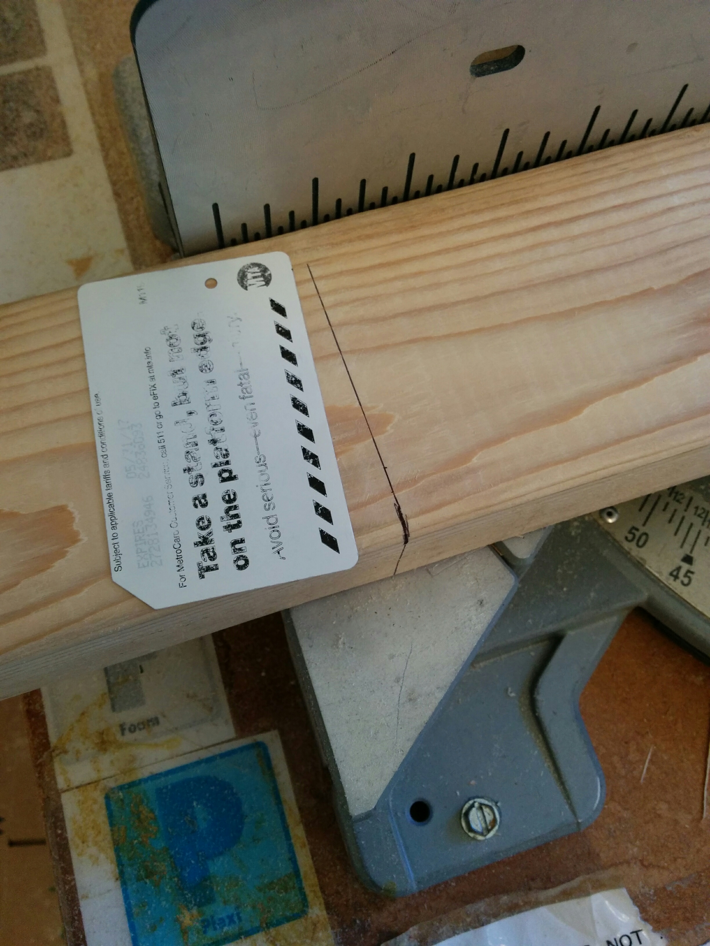
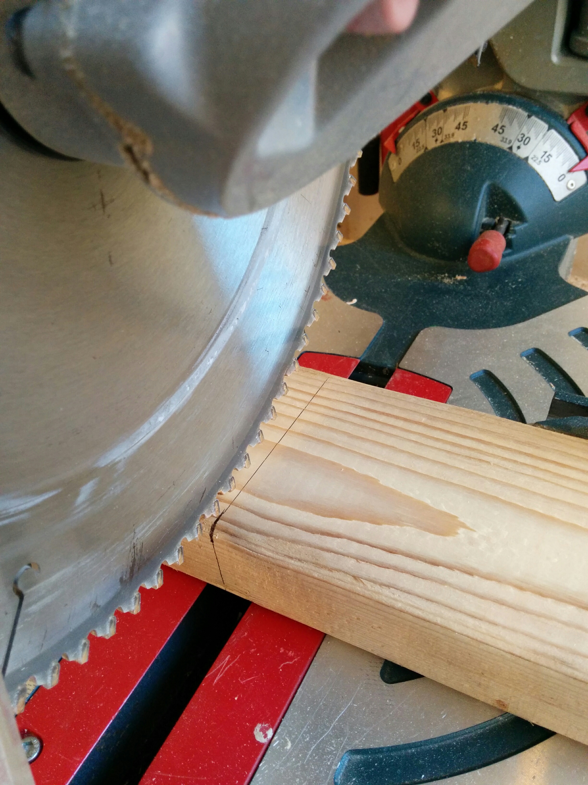
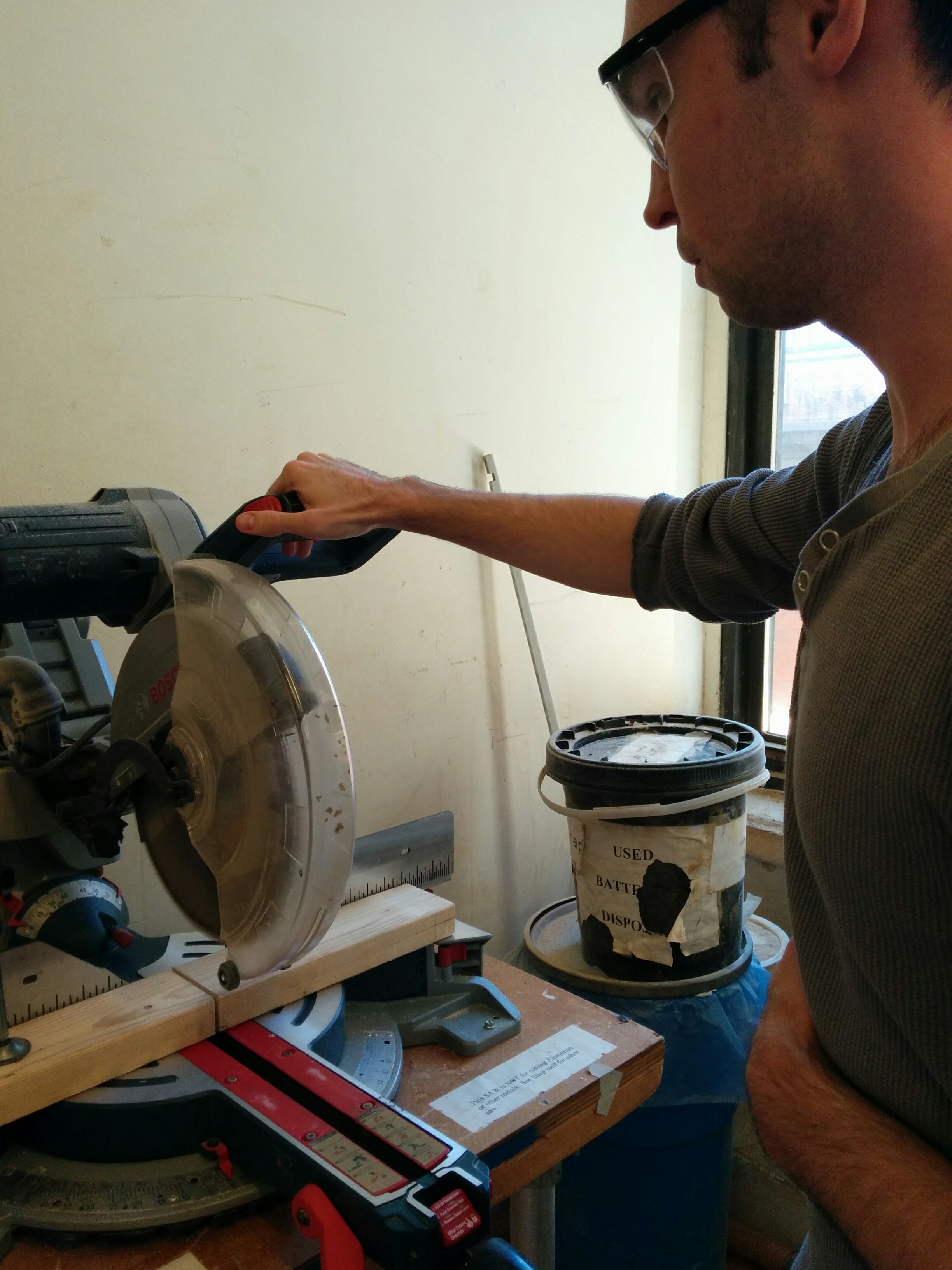
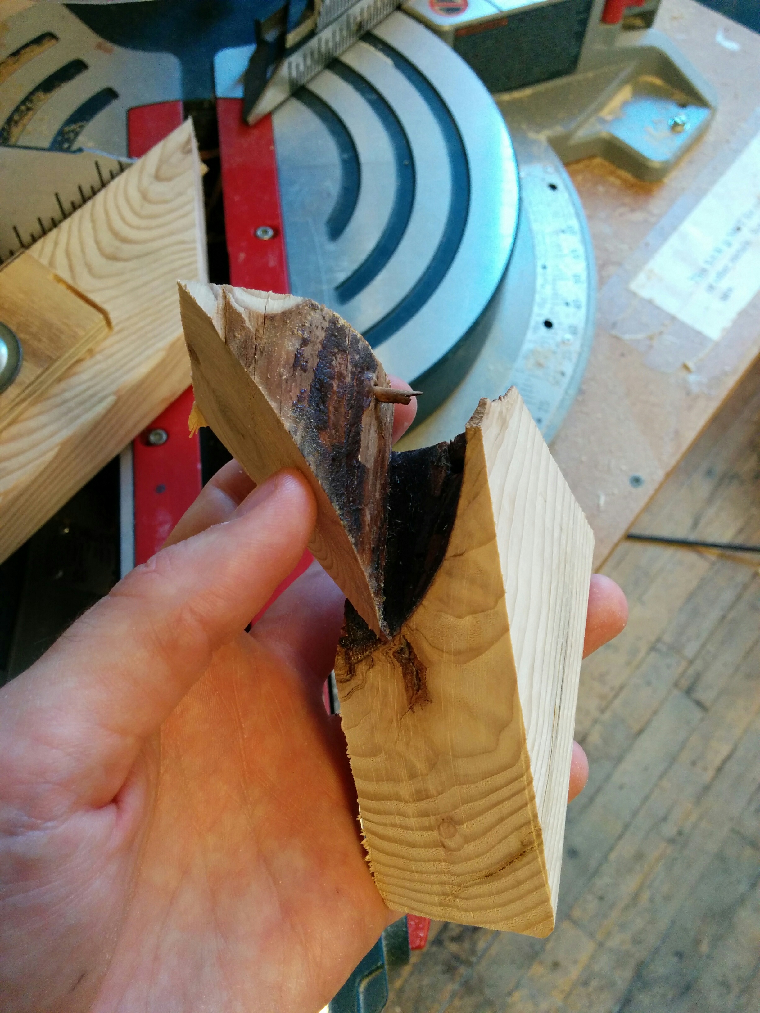
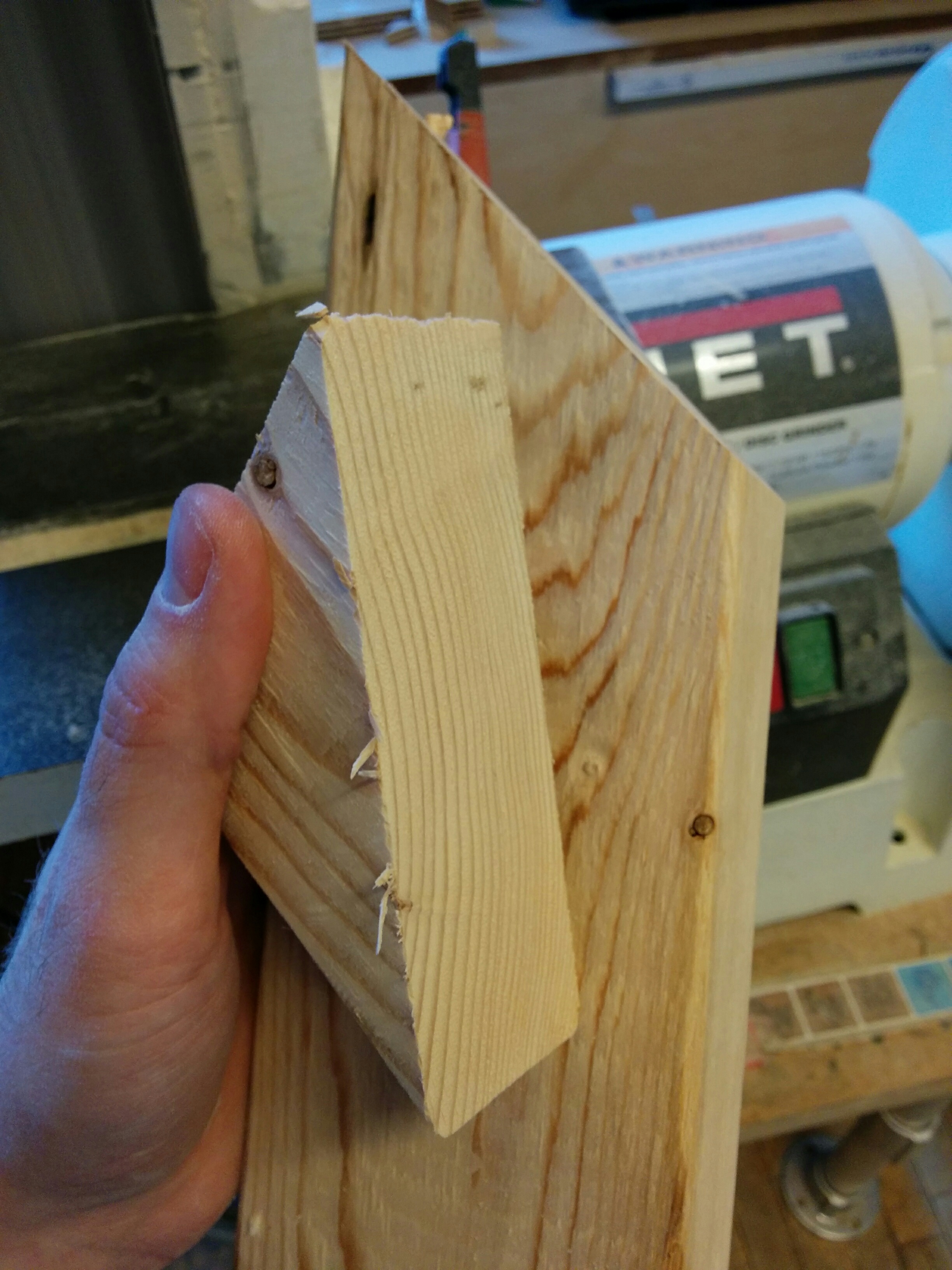
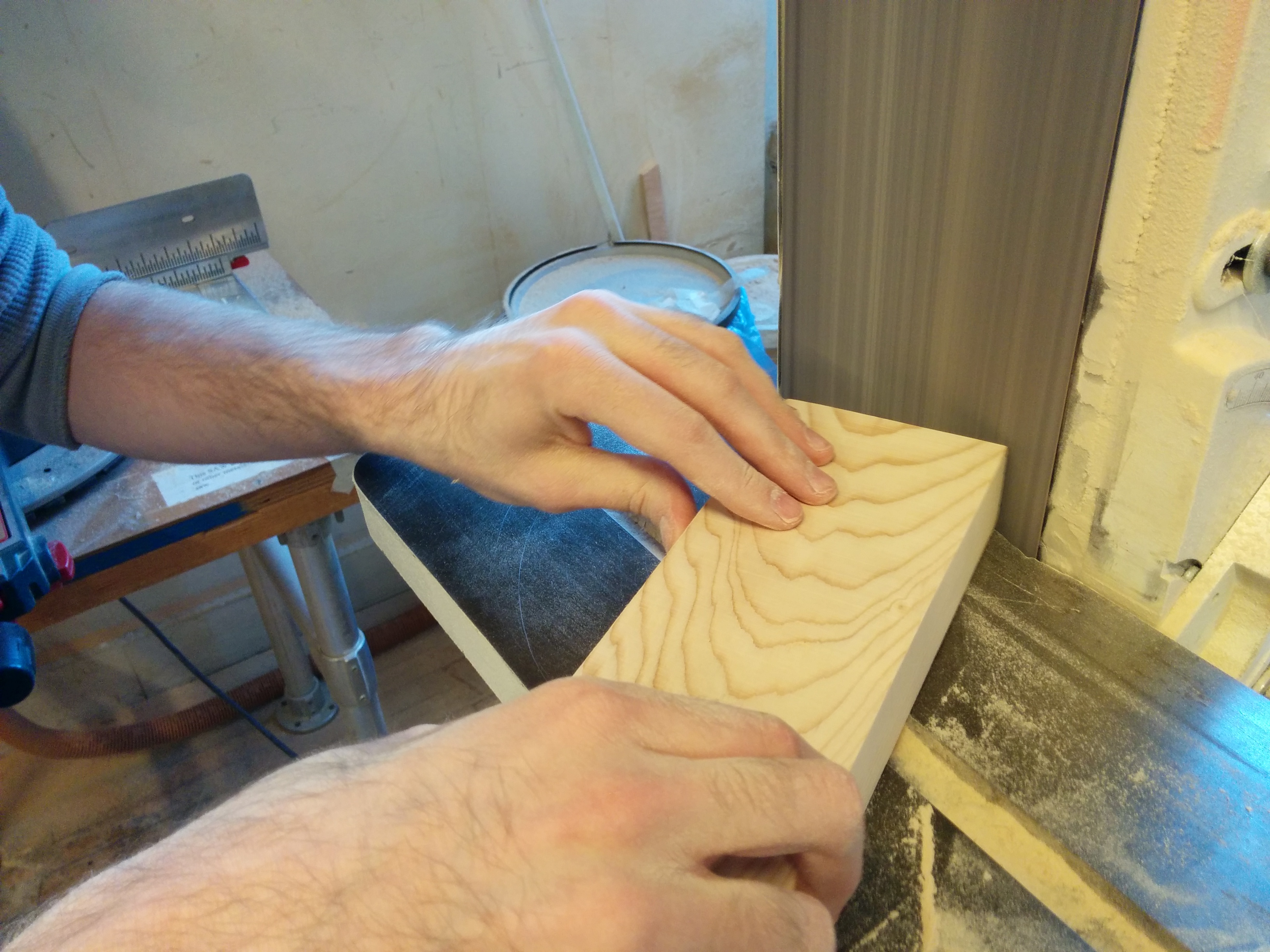
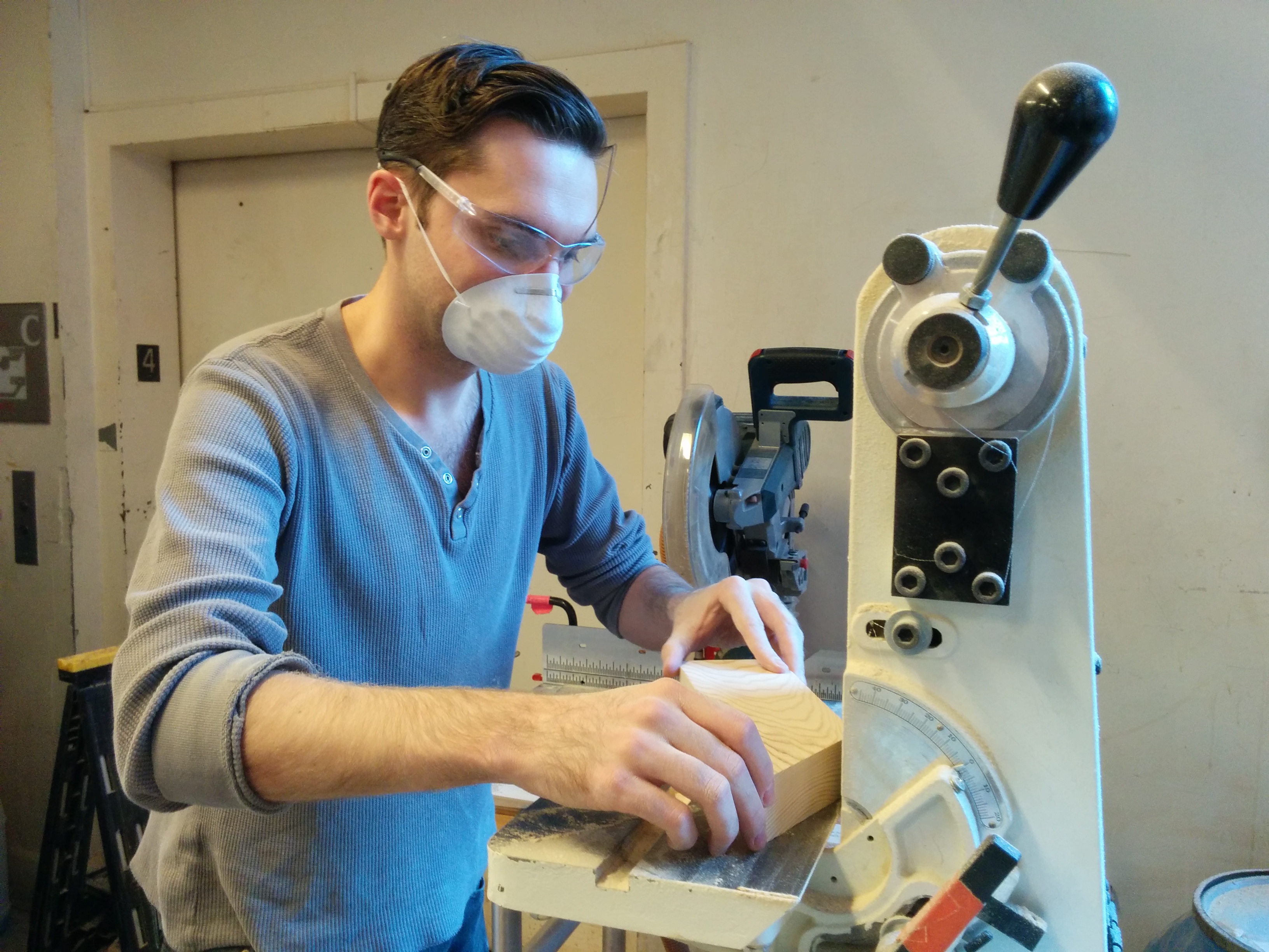
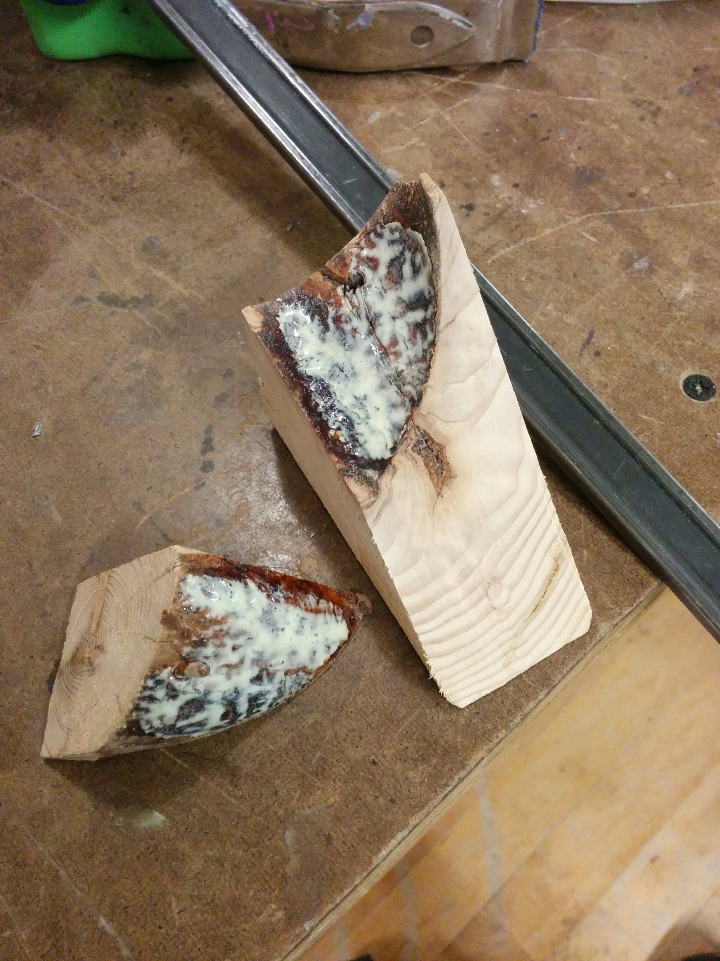
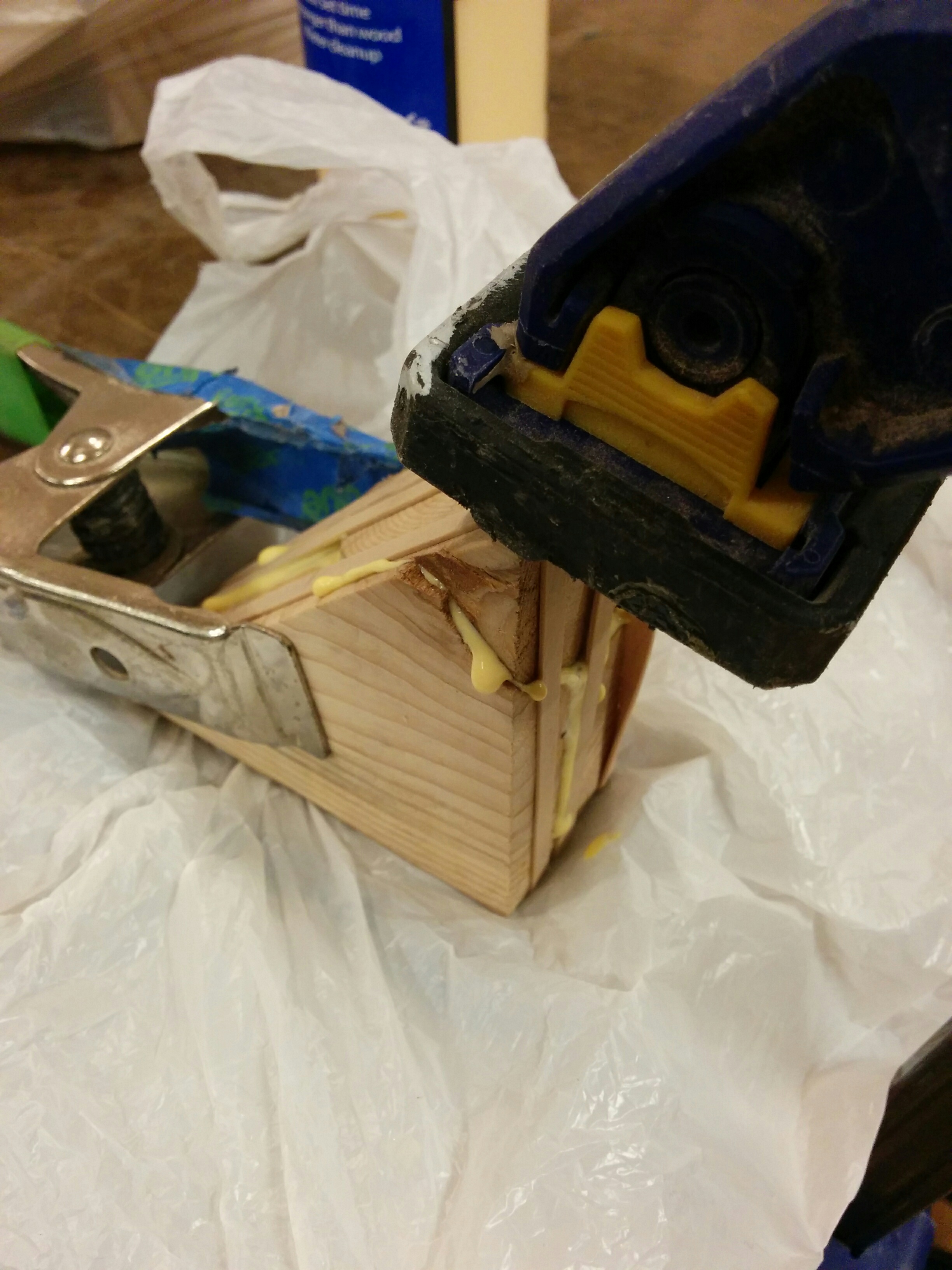
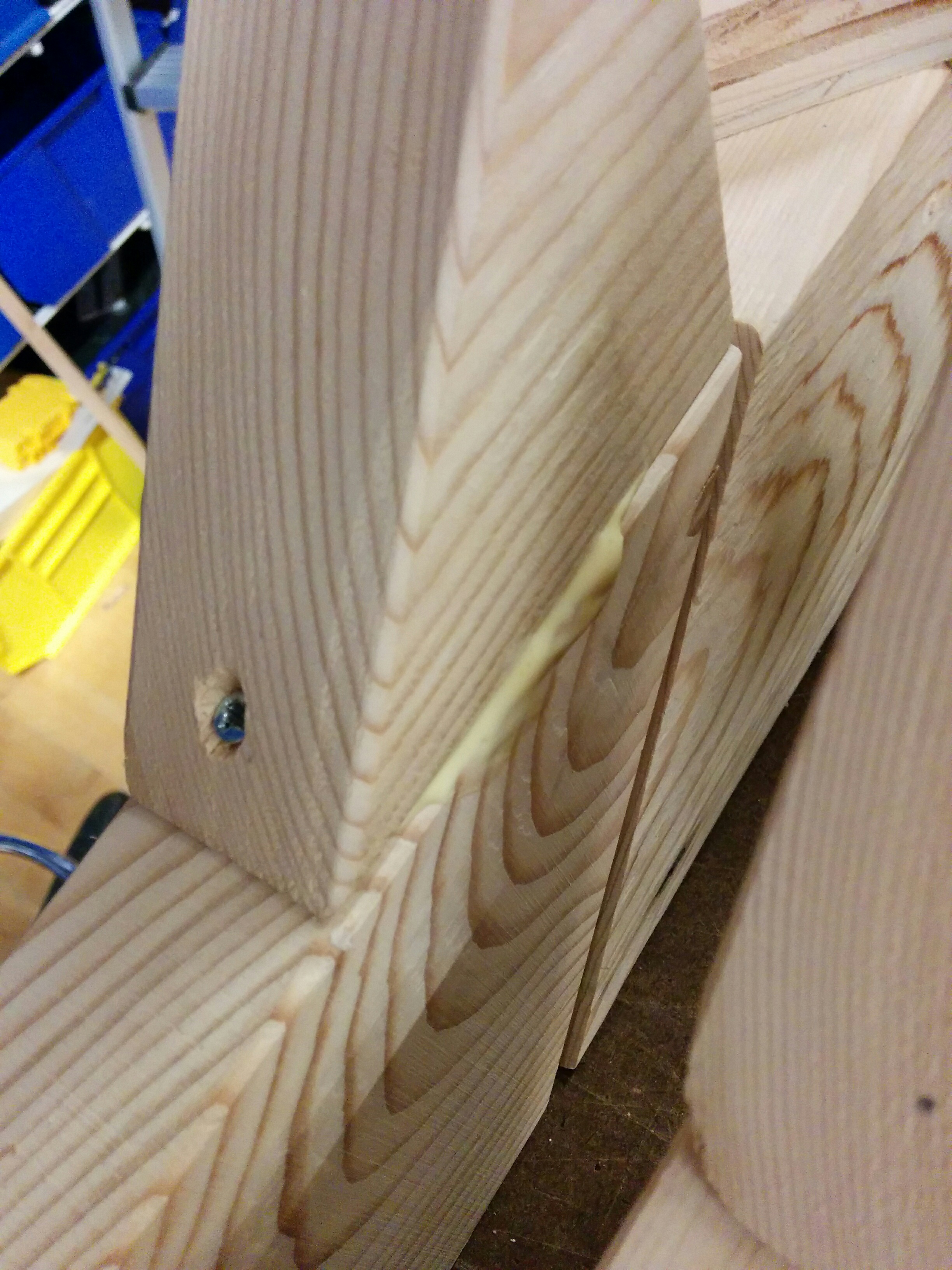
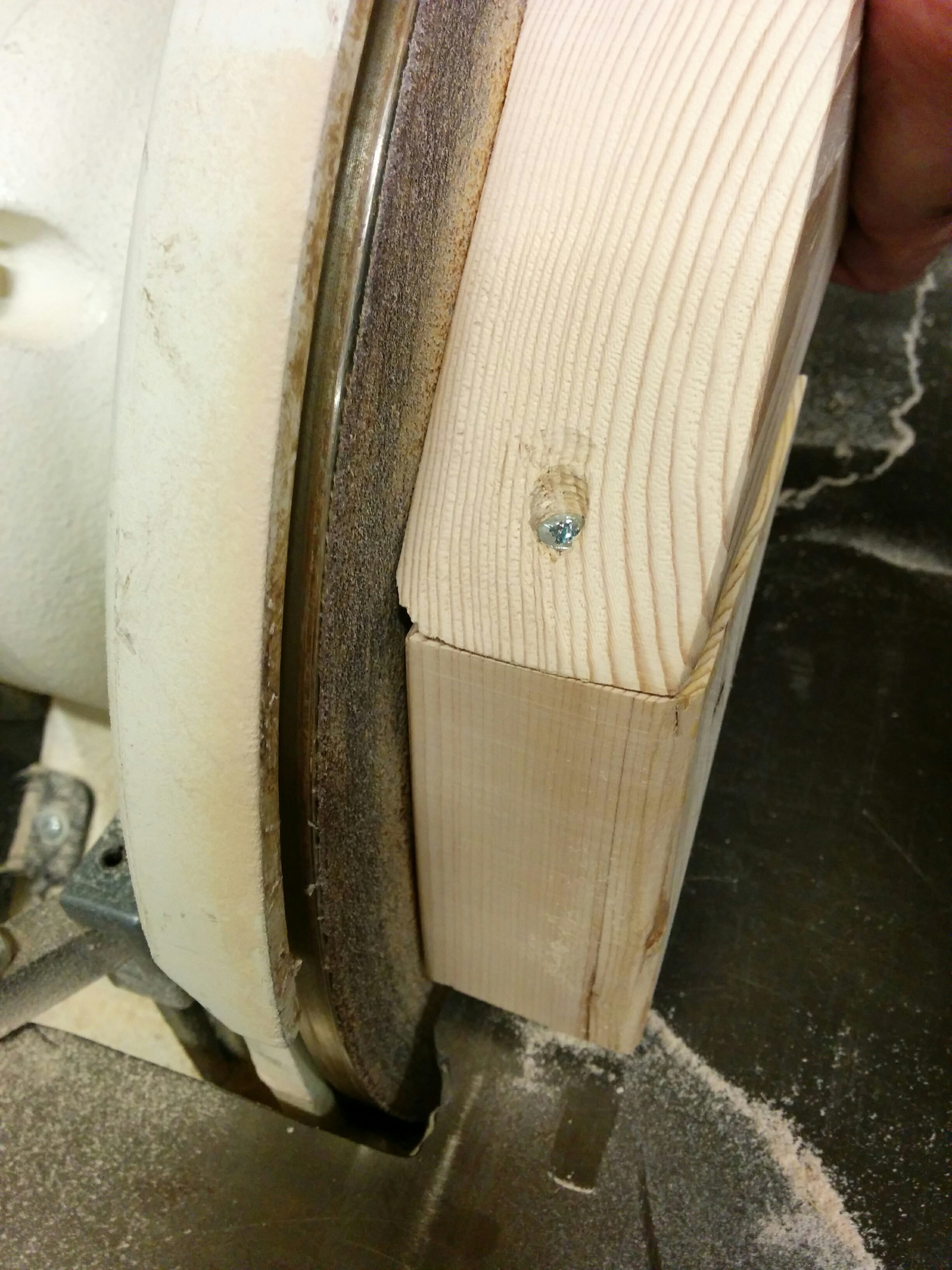
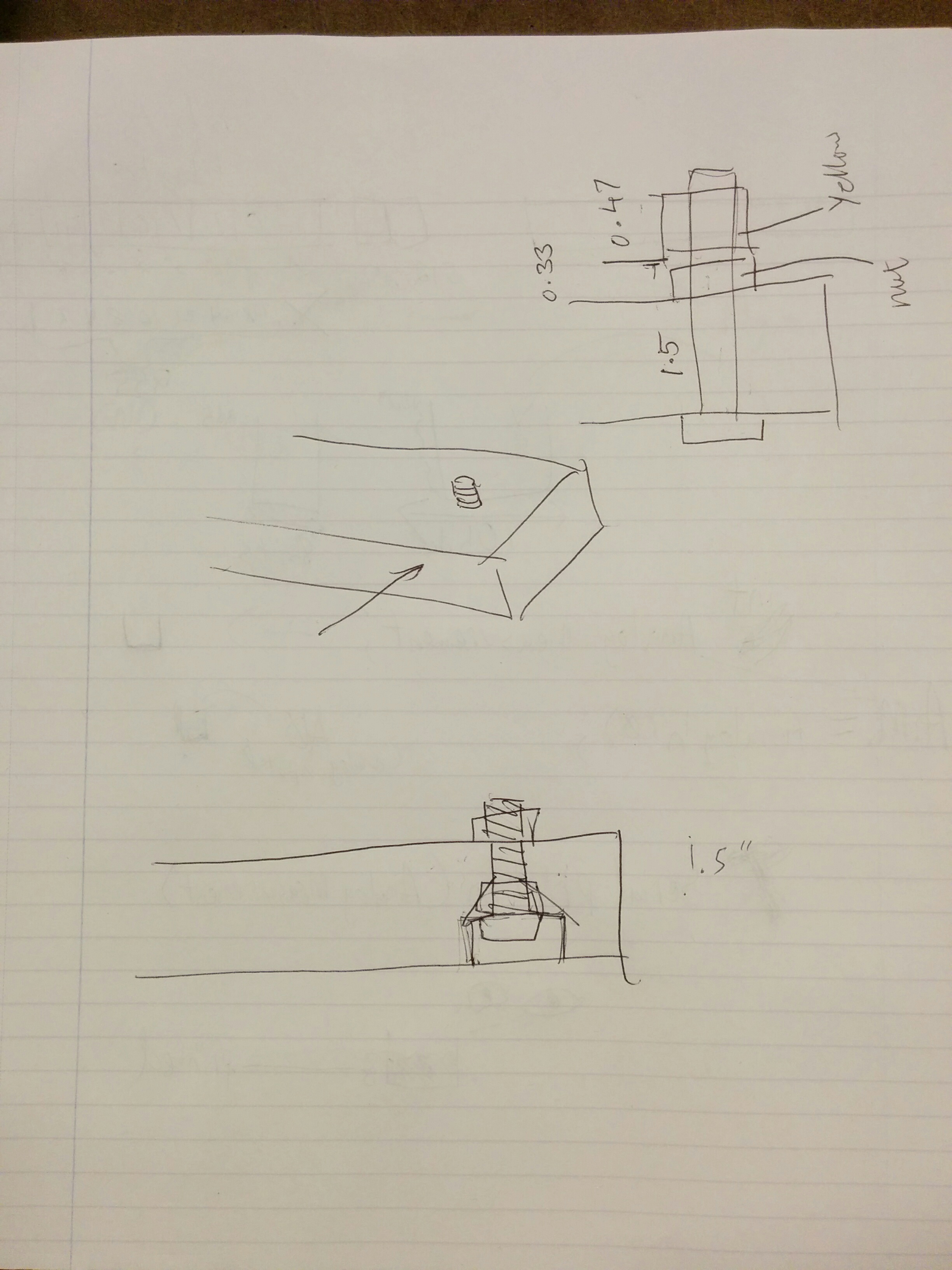
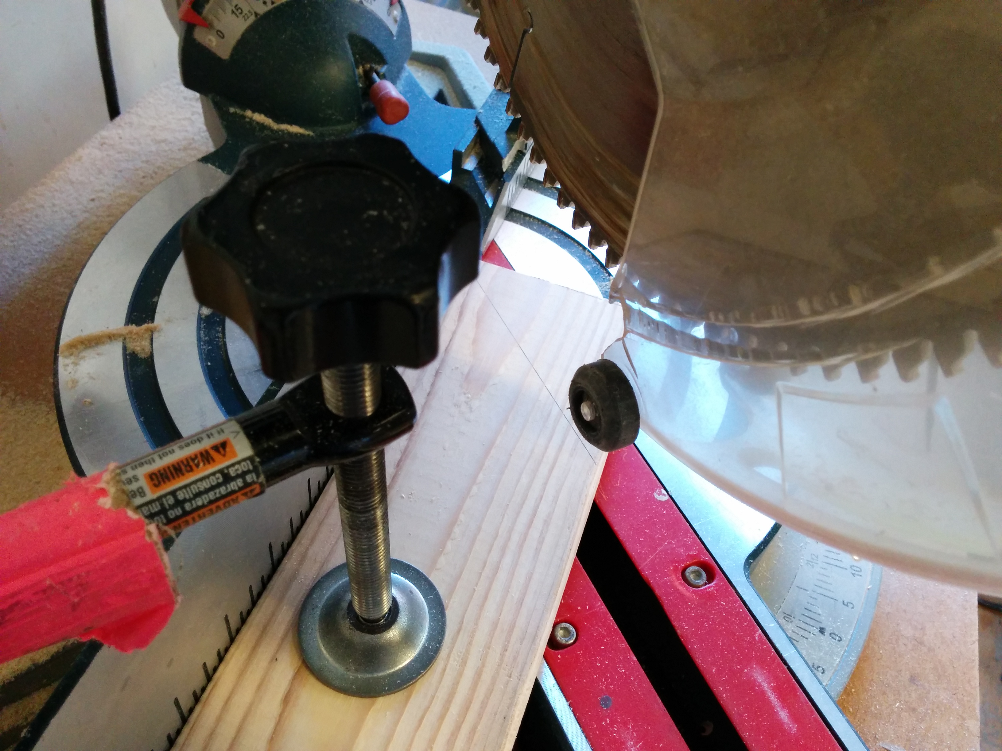
I still my cork from the fastening project, so I decided I would use the pipes from that and mount the motor to the cork. I hit it with the band saw…

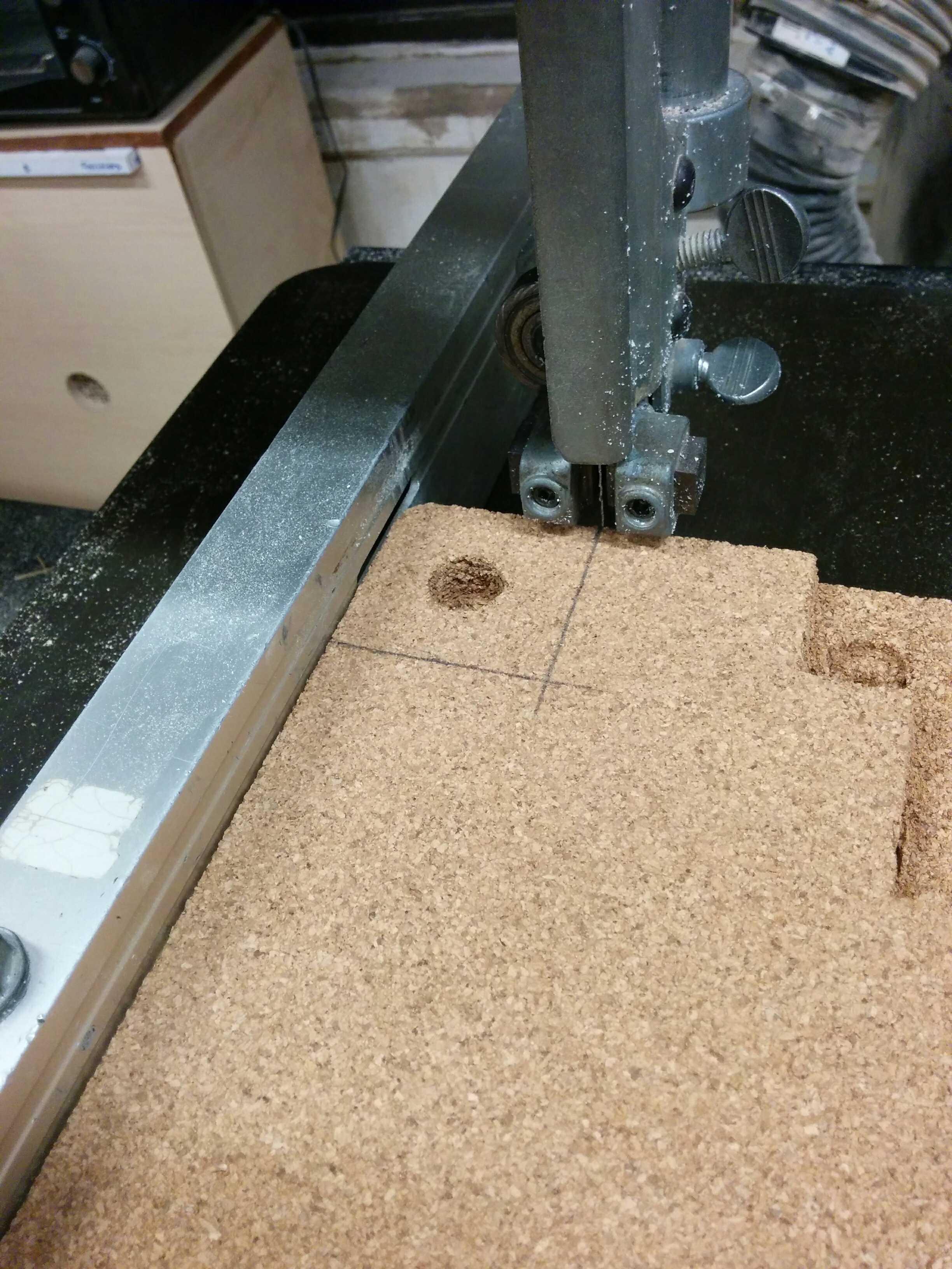
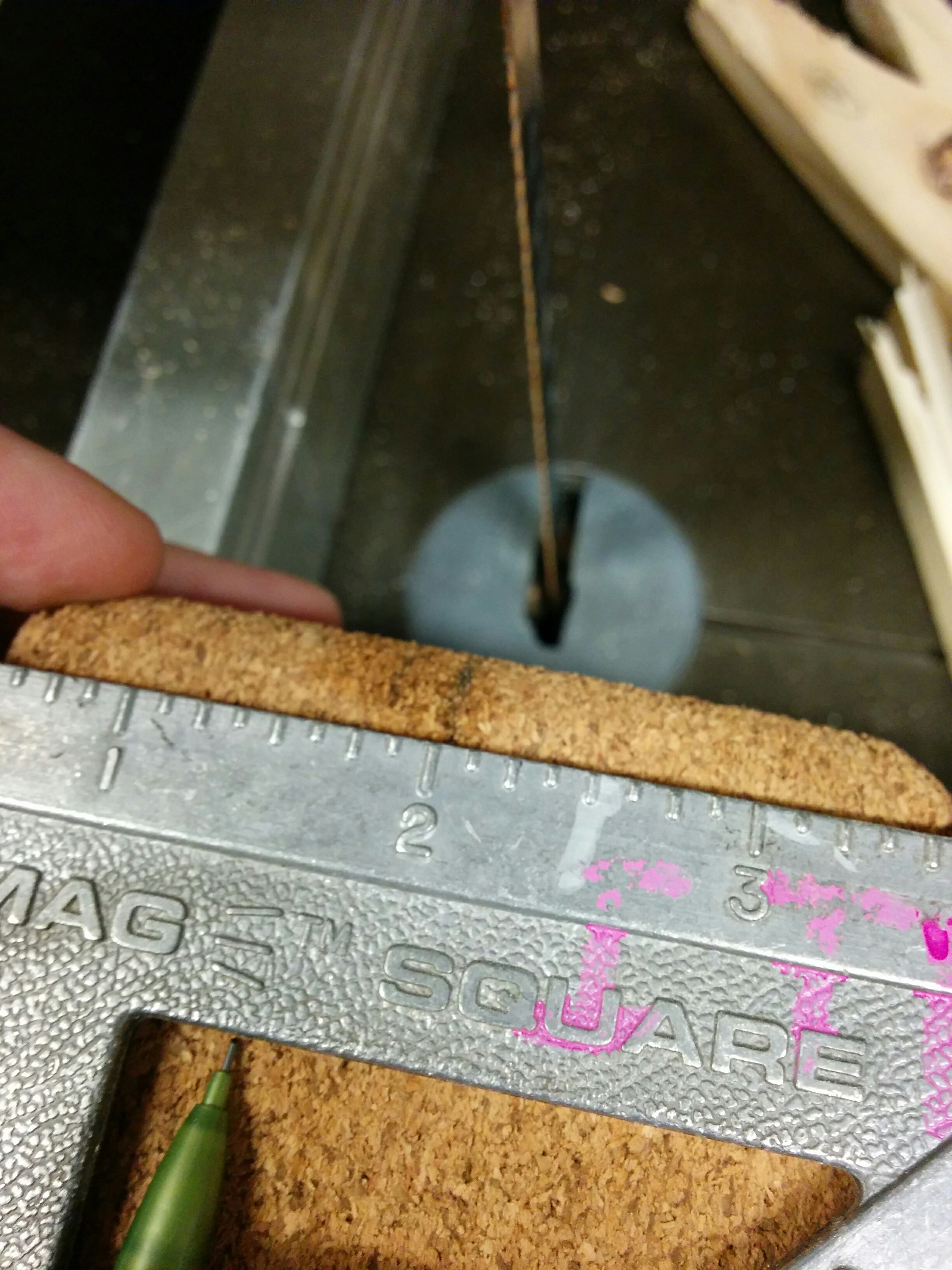
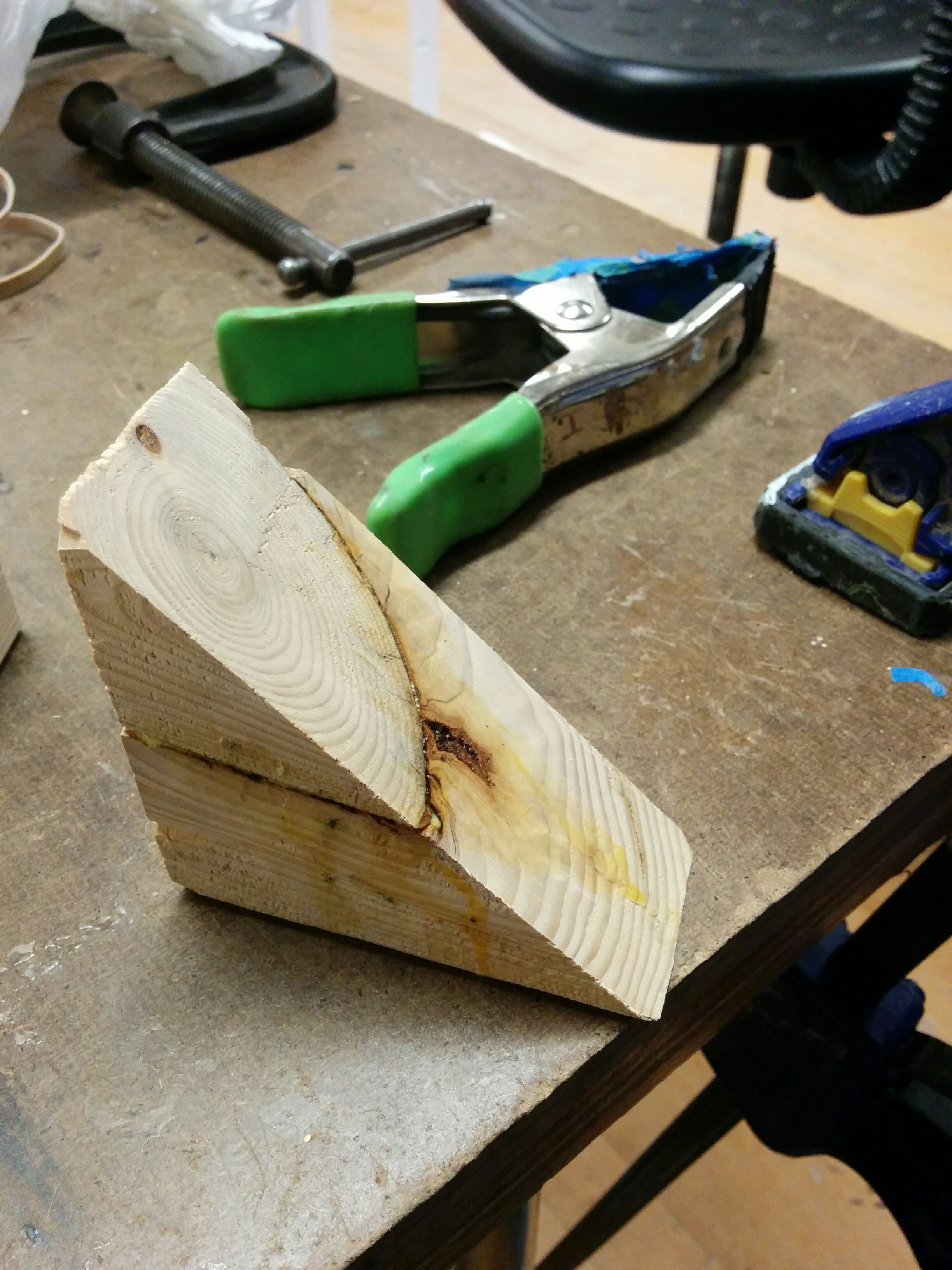
And then tried the other cut, and realized there were space issues on the band saw. I really wanted to keep the band saw fence so I could get somewhat straight results, so I flipped the cork and cut.

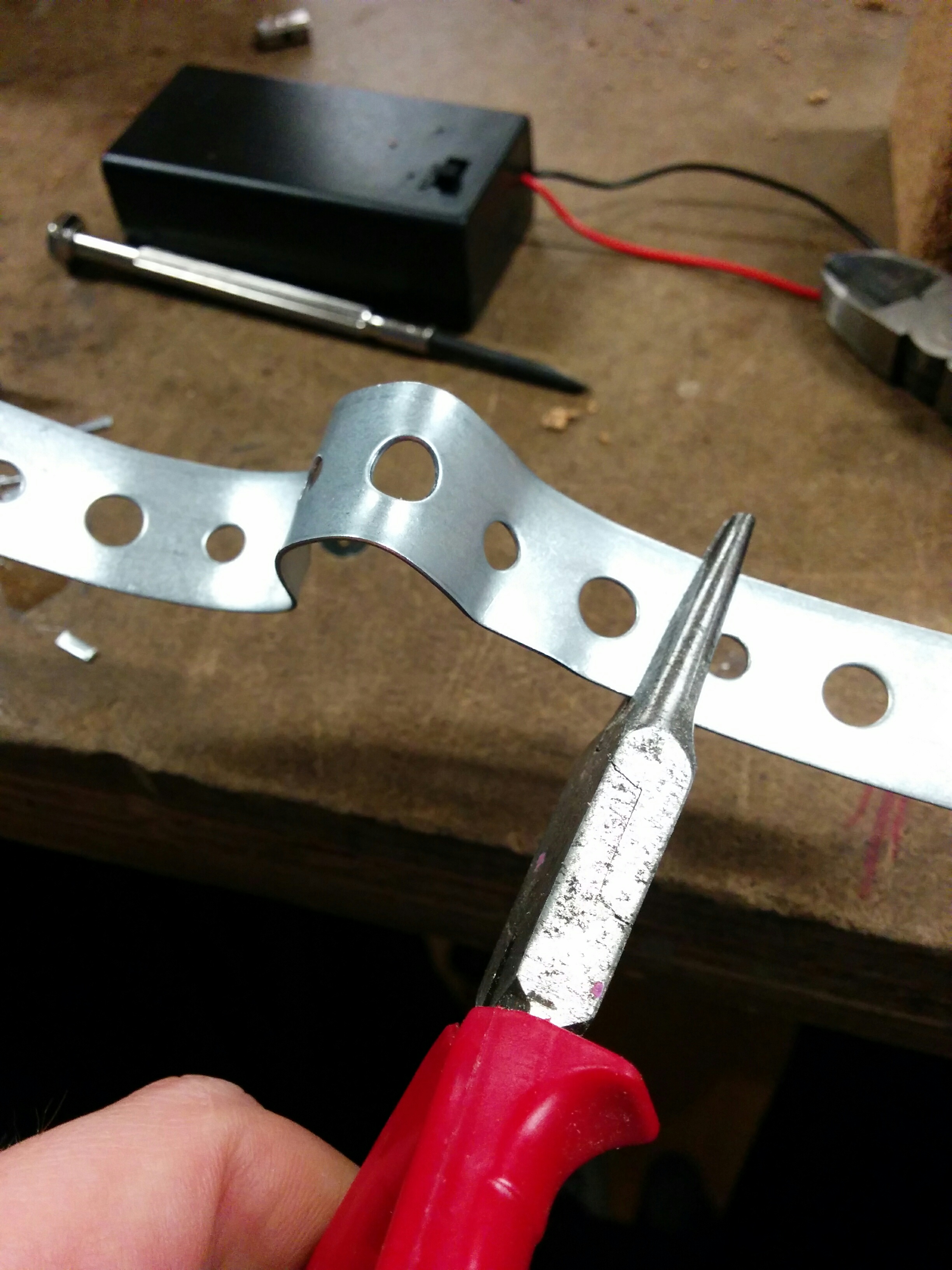
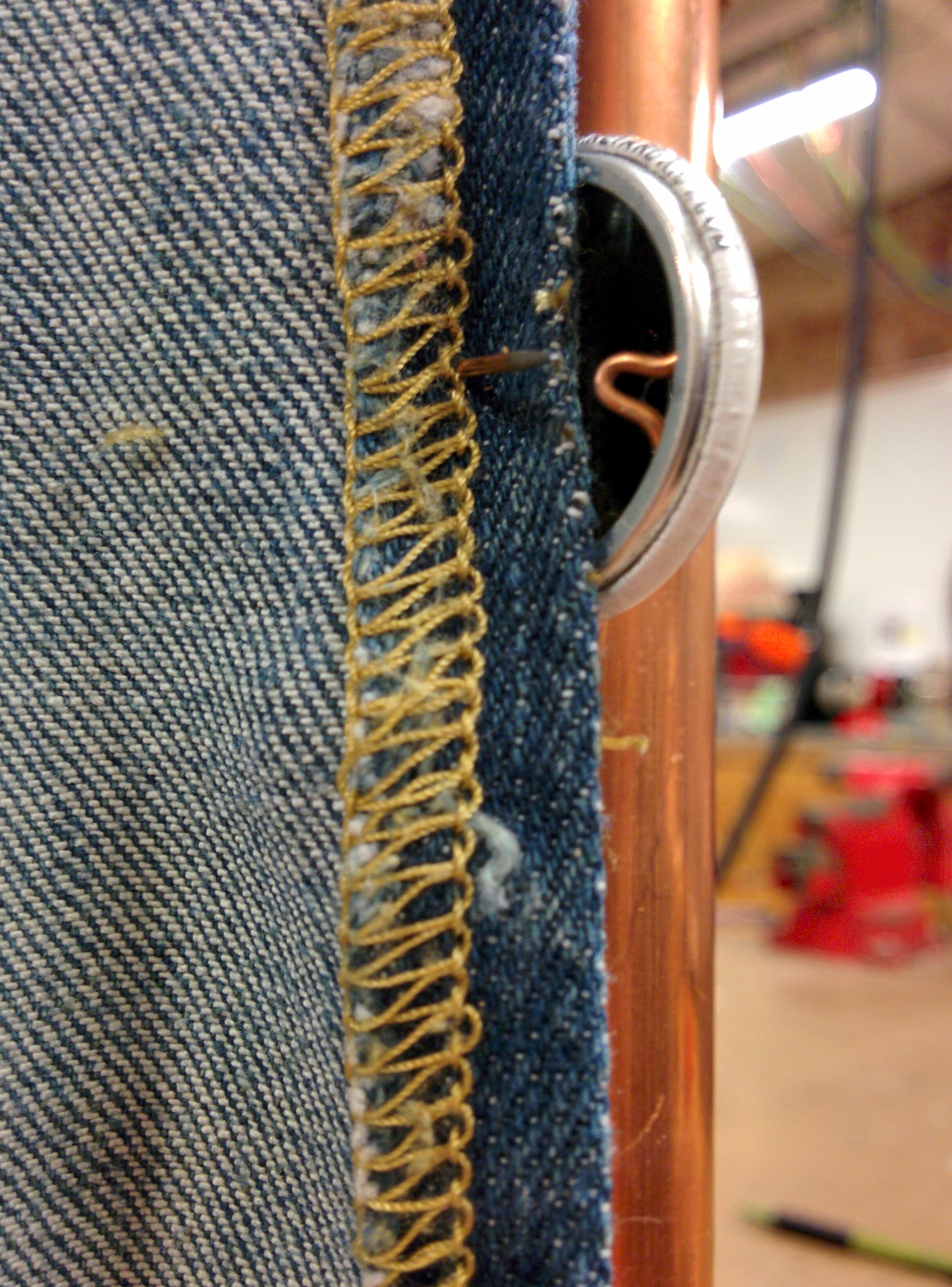
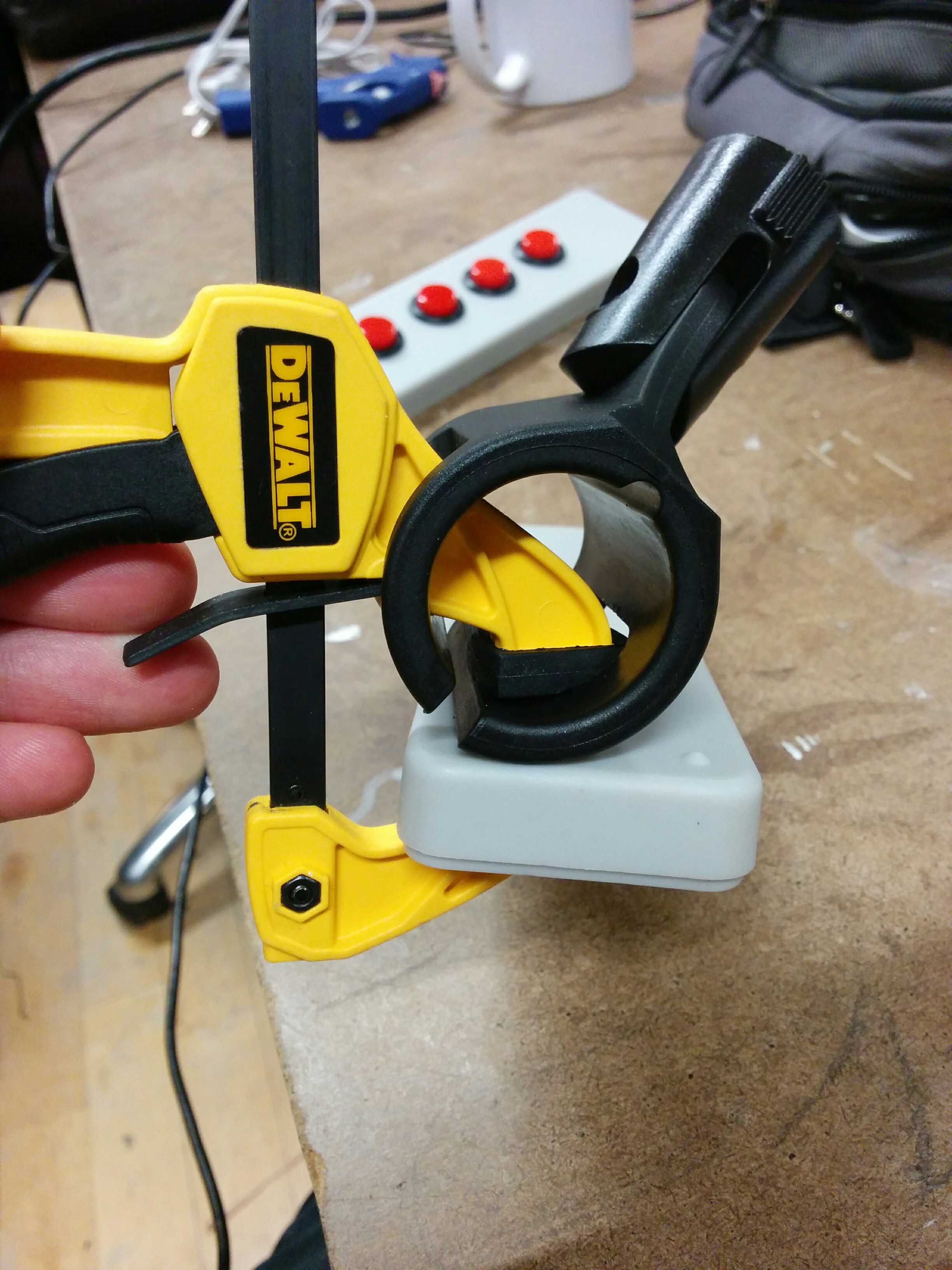
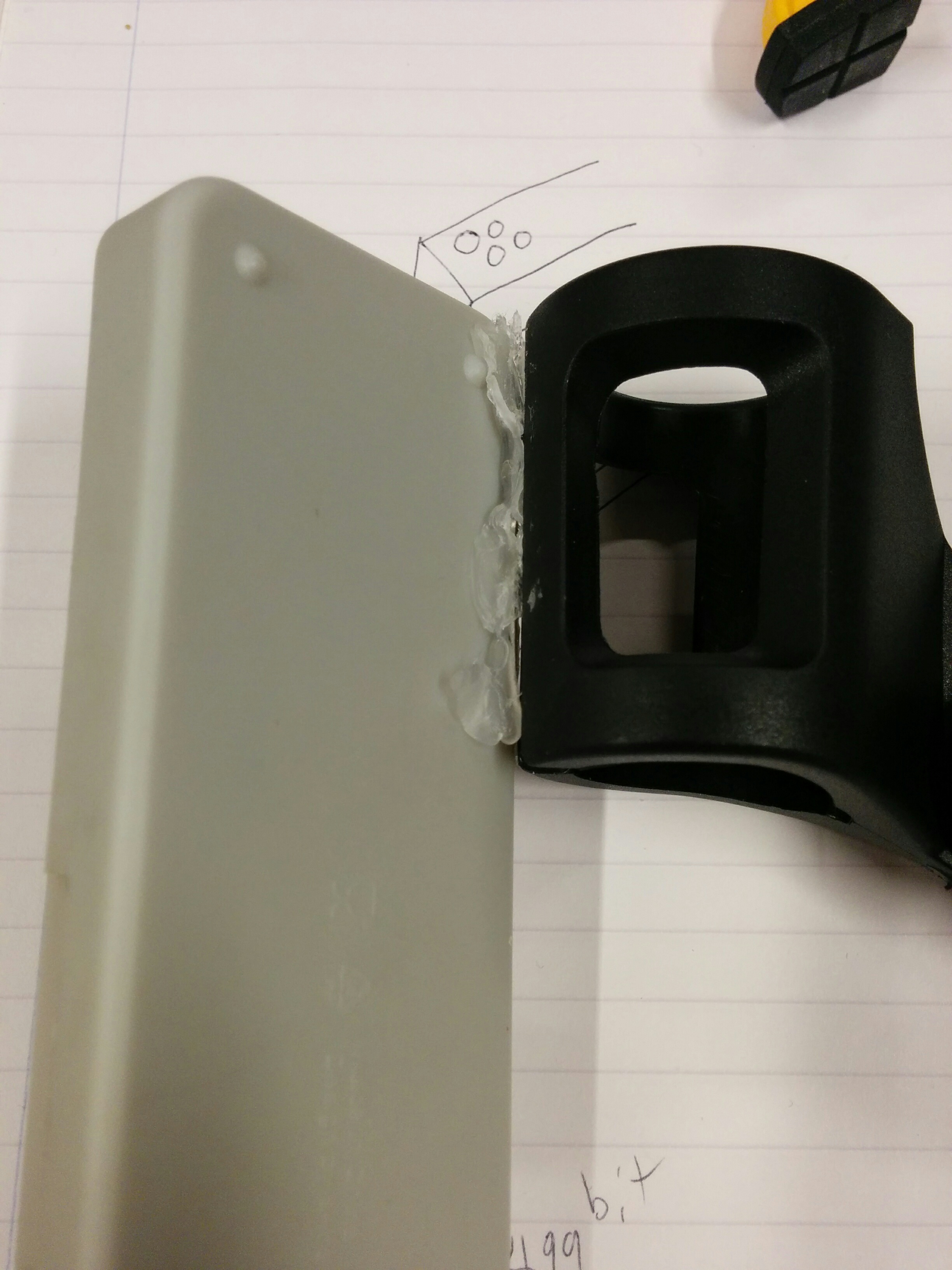
I had gone to the hardware store and gotten the metal bands with circles in them. We didn’t have any snips in the shop that could cut them, but the nibbler came through to save the day.

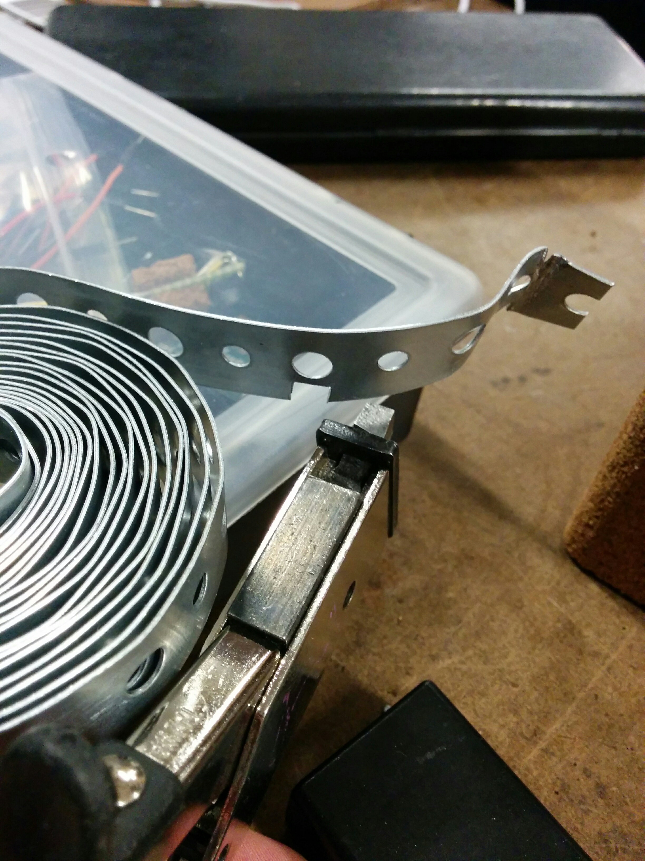
Then shaping the form of the band. Not as easy as it looks. The stiffness didn’t allow for very elegant shaping, but it did feel extremely sturdy.

Now back to my original issue:

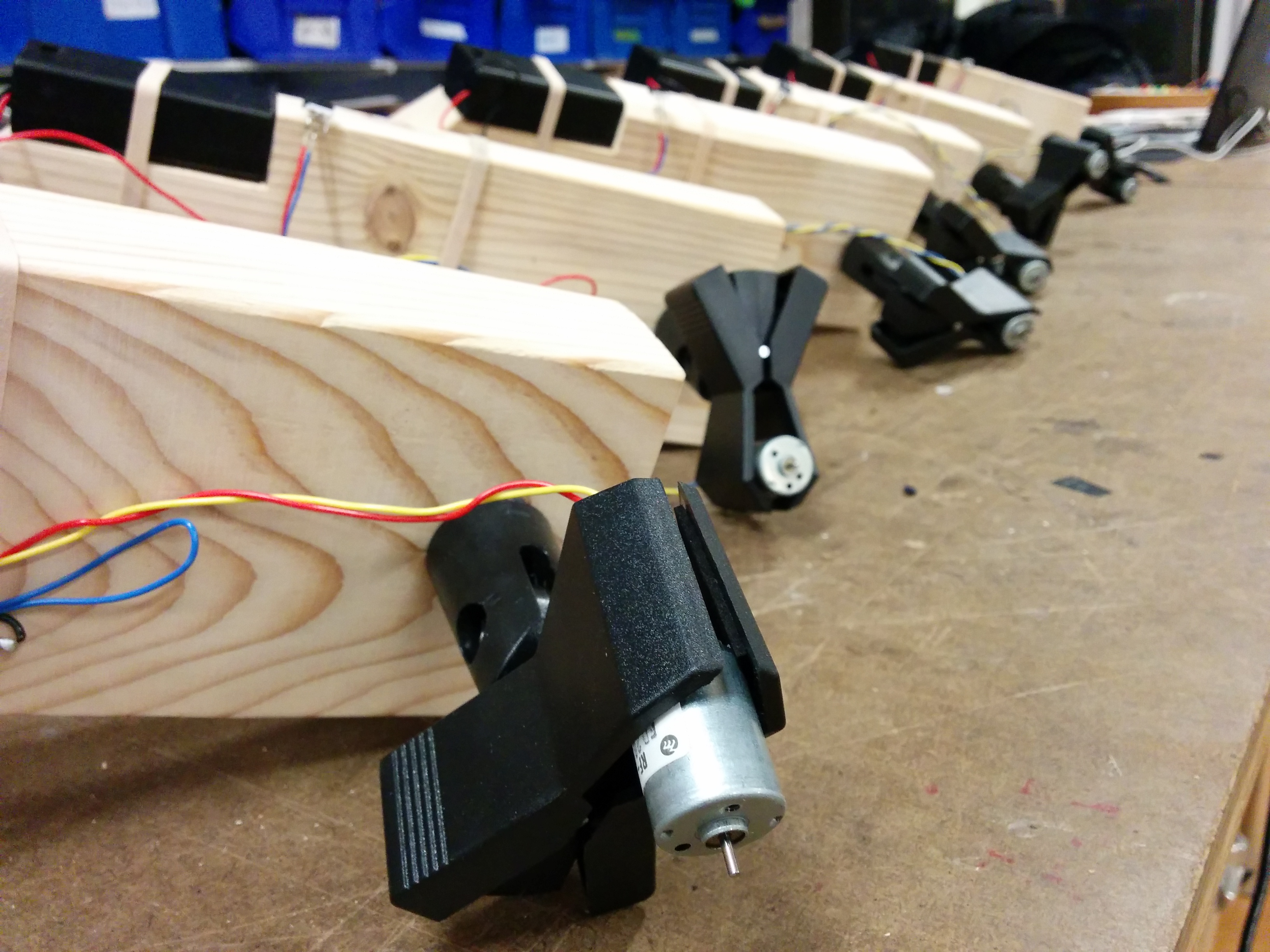
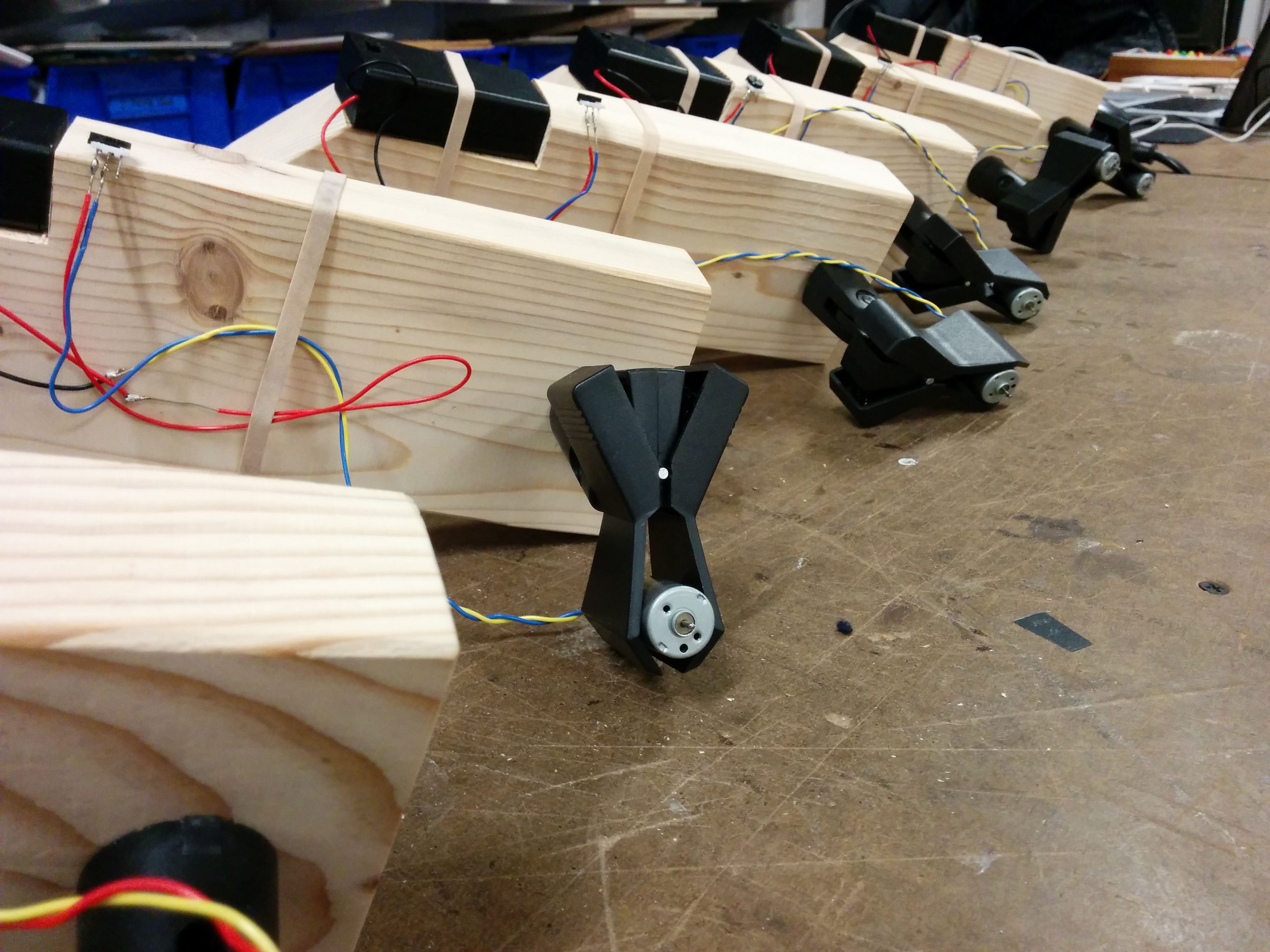
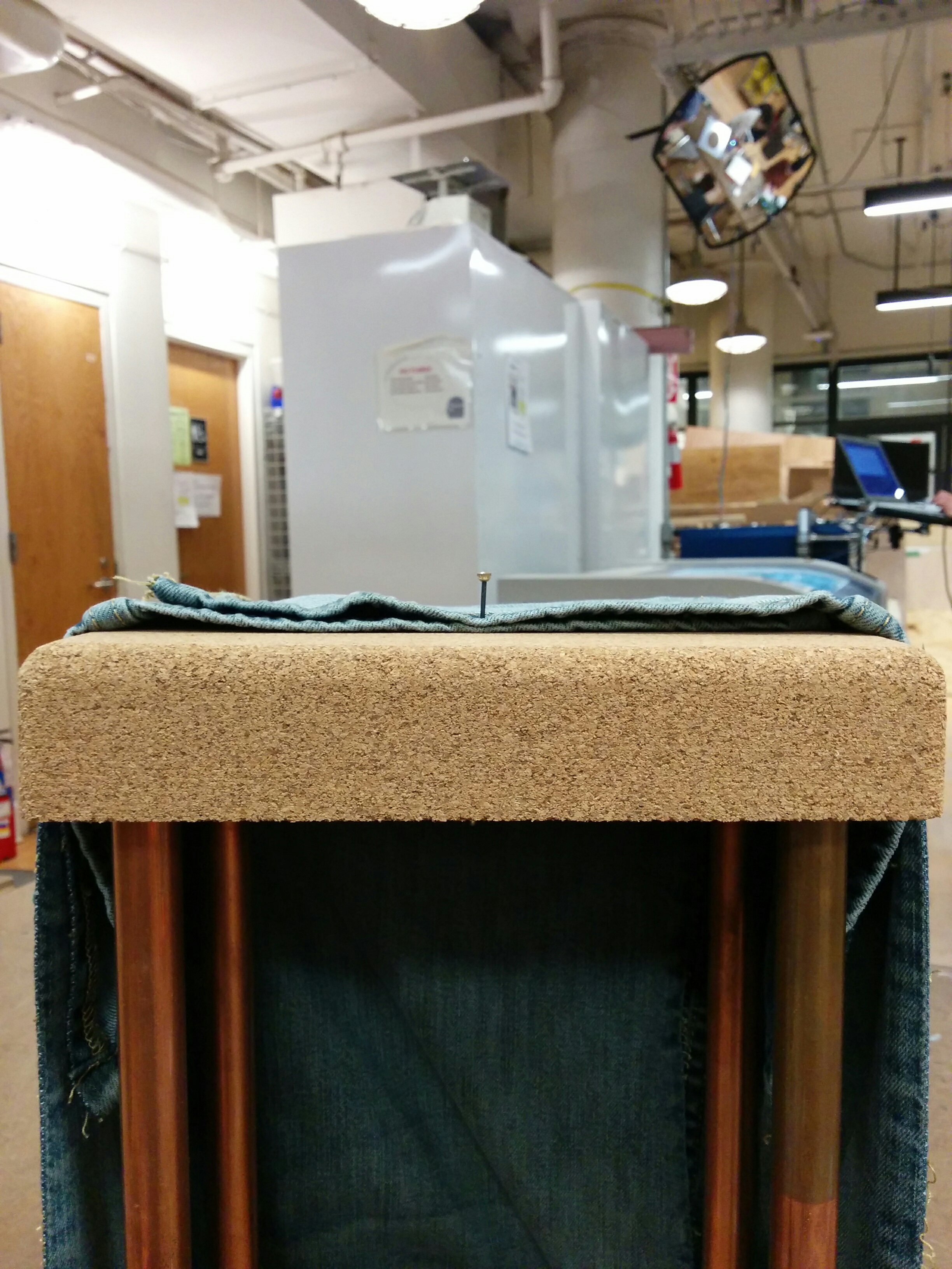
I created a 90 degree hinge for the couplers. (The straight male to male headers had more distance than the pre-bent 90 degree headers). Then I mounted both, thinking that perhaps giving the thread it’s own straight direction away from the axle, it might not get tangled on itself.

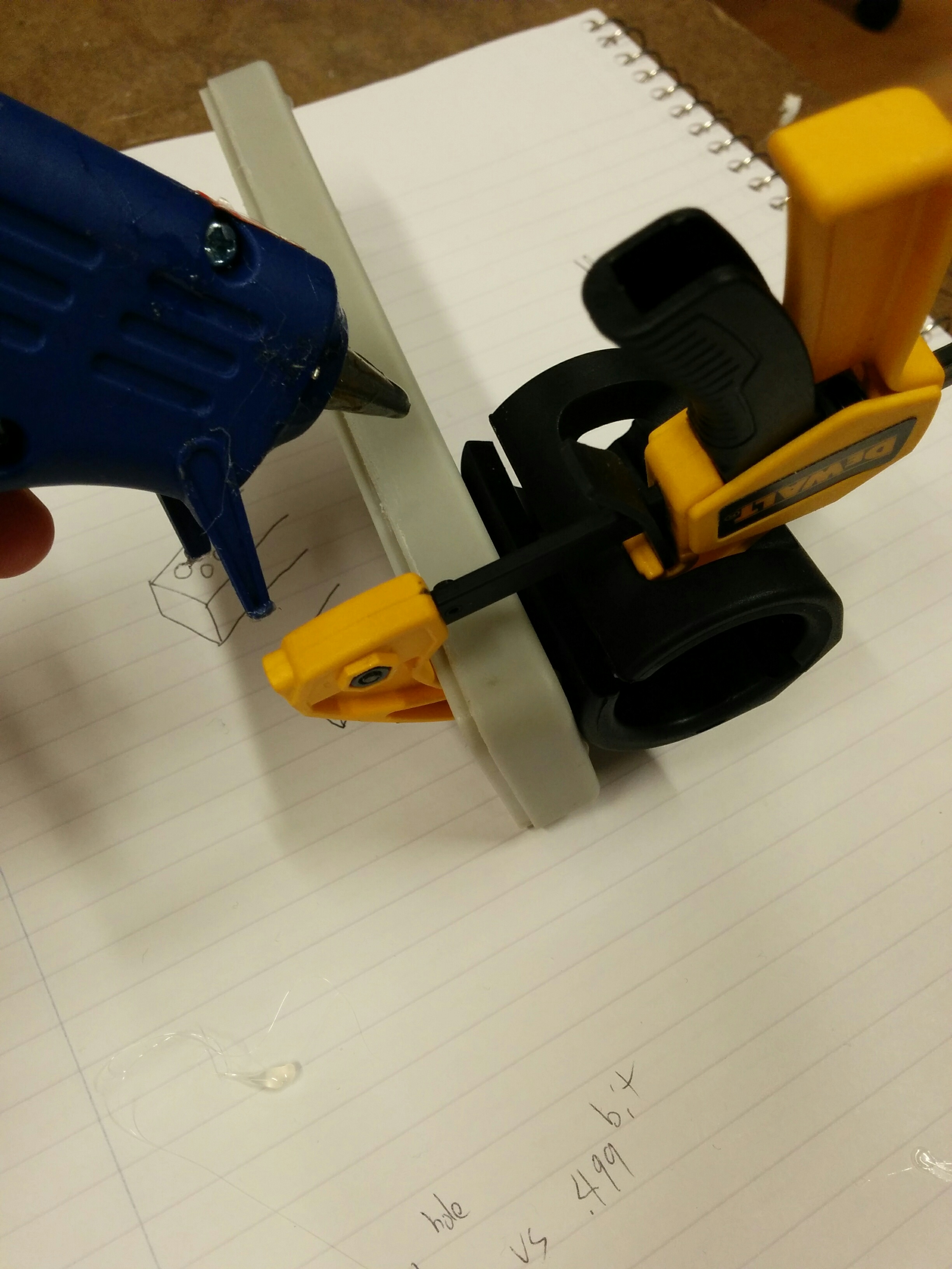
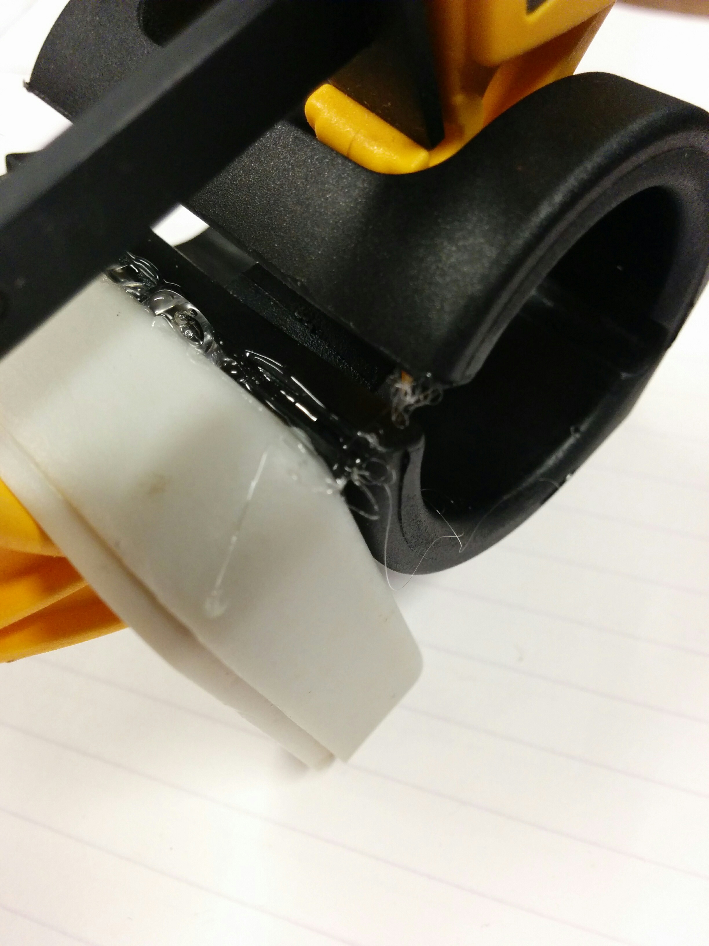
Plus a little bit of weight at the end. But nothing too heavy, so it was less of a weapon and more of an instrument. I had kept these foam balls I had bought for the original multiples project. Hot glue and some tape to prevent the foam from chipping and making dust everywhere (it’s a kind of… crispy? foam that flakes off).

And the test:

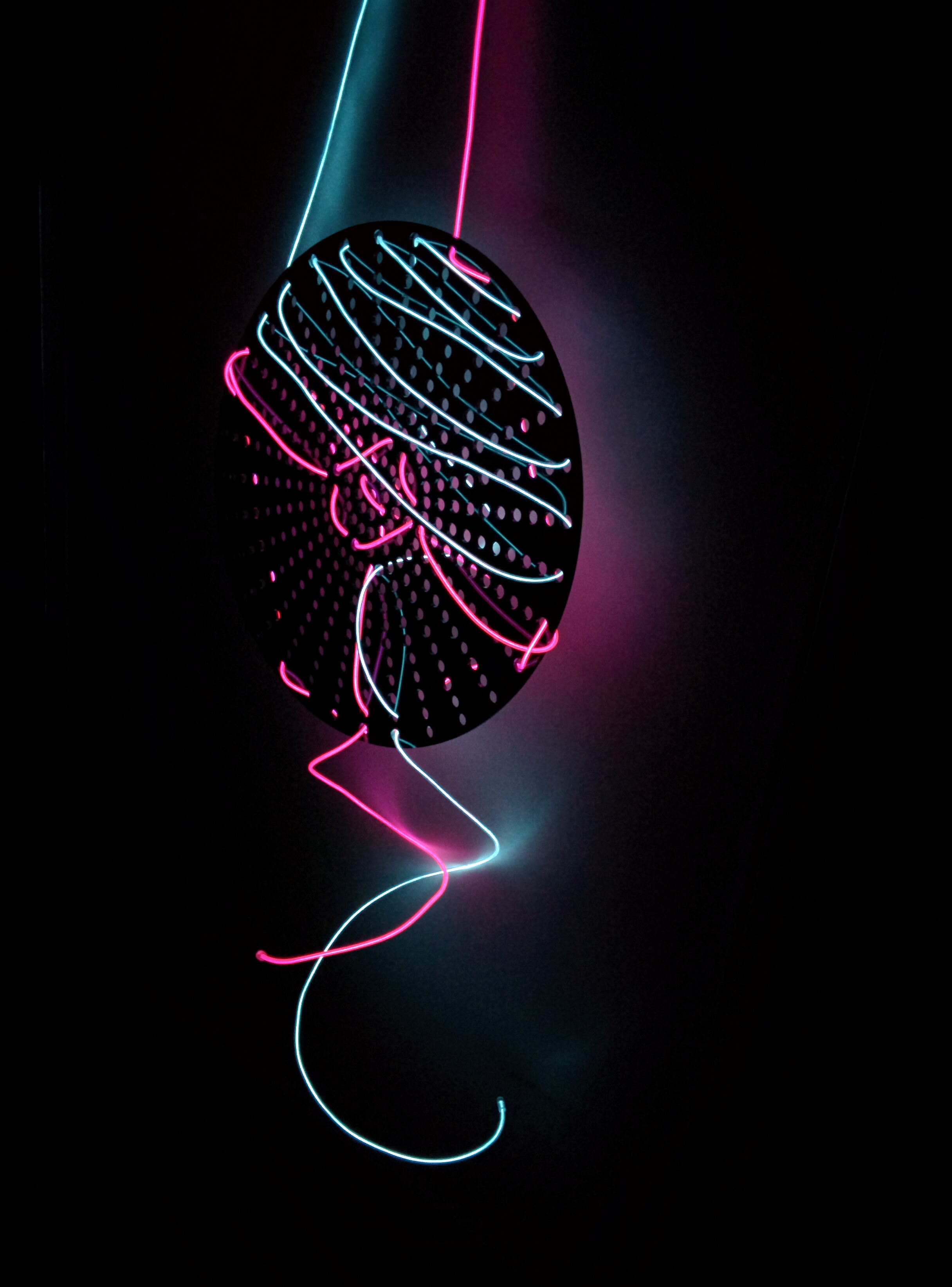
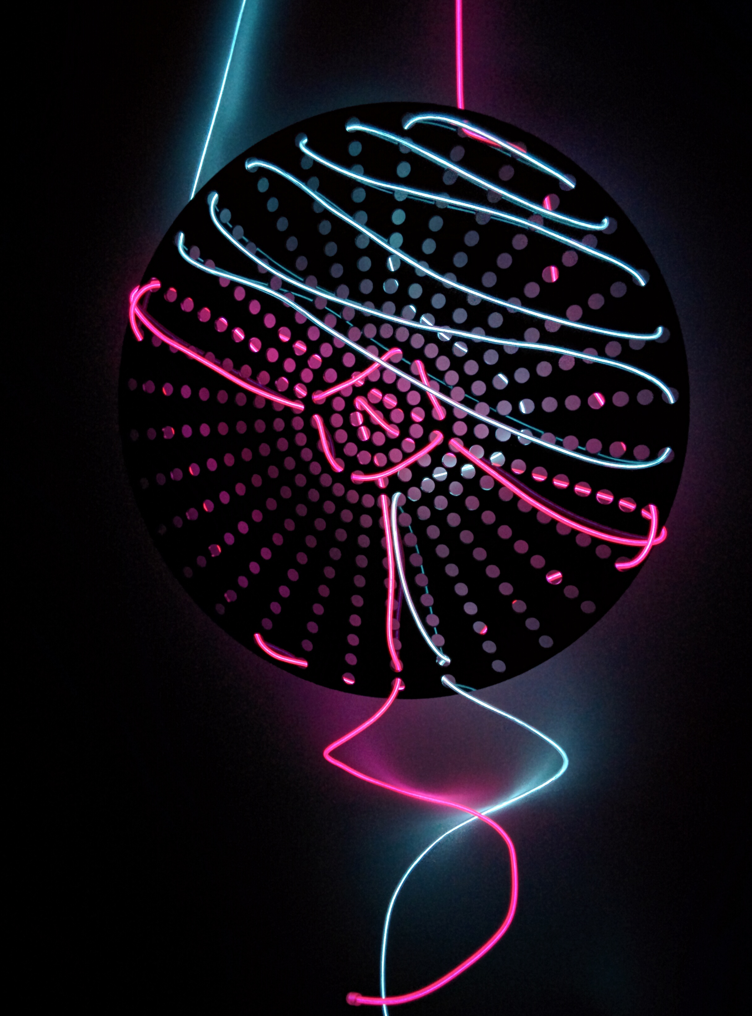
Yeesh. It looks to me like I will either need more distance from the shaft or a mounted wheel to achieve the effect I am going for. I’ve also considered flexible, but a bit more firm material than something like string. Maybe fishing line or a semi-rigid wire? I’m going to continue to hunt for the appropriate materials and try a few things out. But for now, some photos of what I have:

12-14-16, I’m adding some extra progress

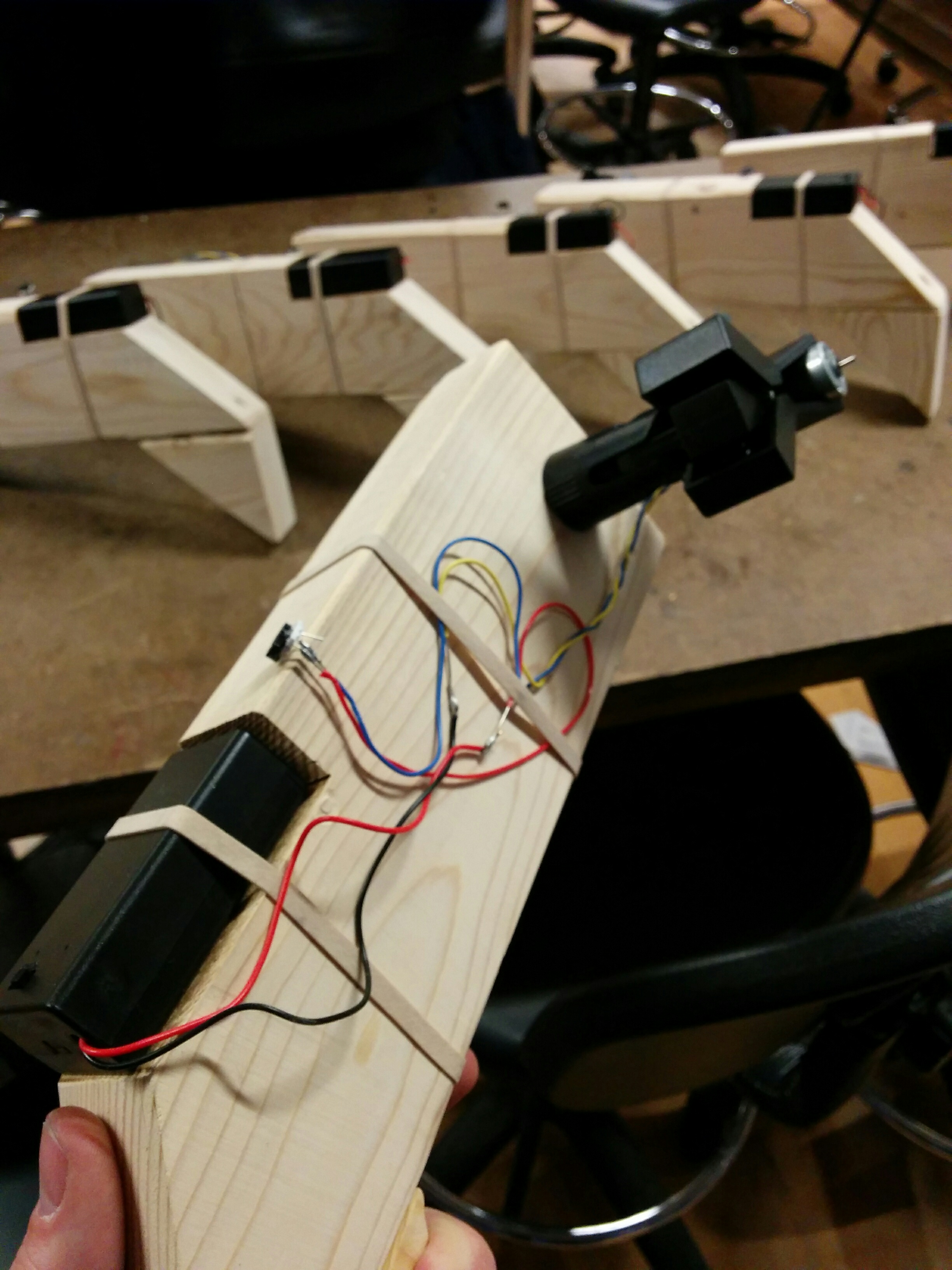
I went to the hardware store and got some thin but stiff wire. Something light, but could stay somewhat rigid.

It was stiff enough to hold a (somewhat) 90 degree angle. It was actually nice to be able to bend it, as it gives the ultimate purpose of making noise a little more flexibility. I reused the ball and hot glued to secure.

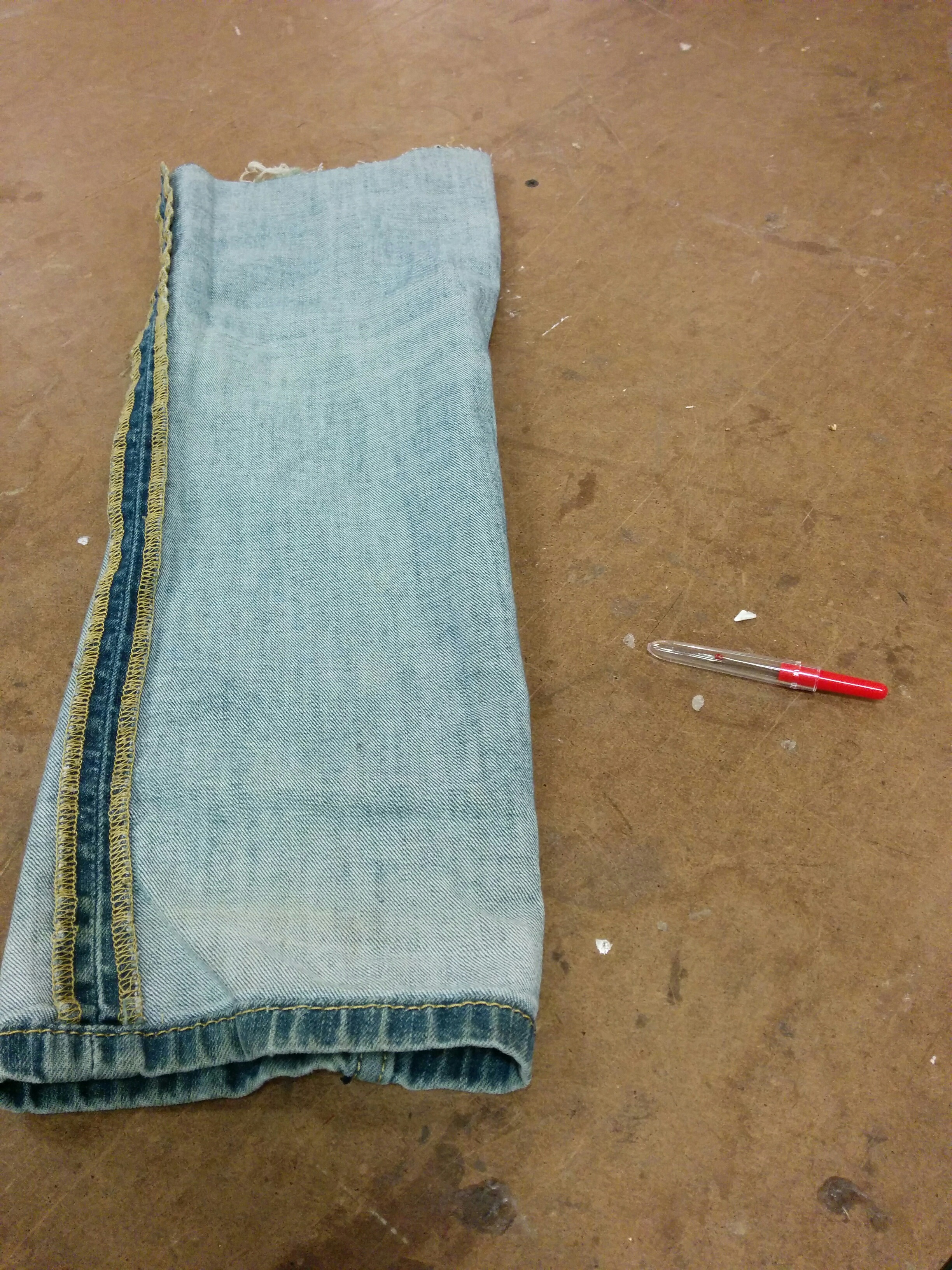
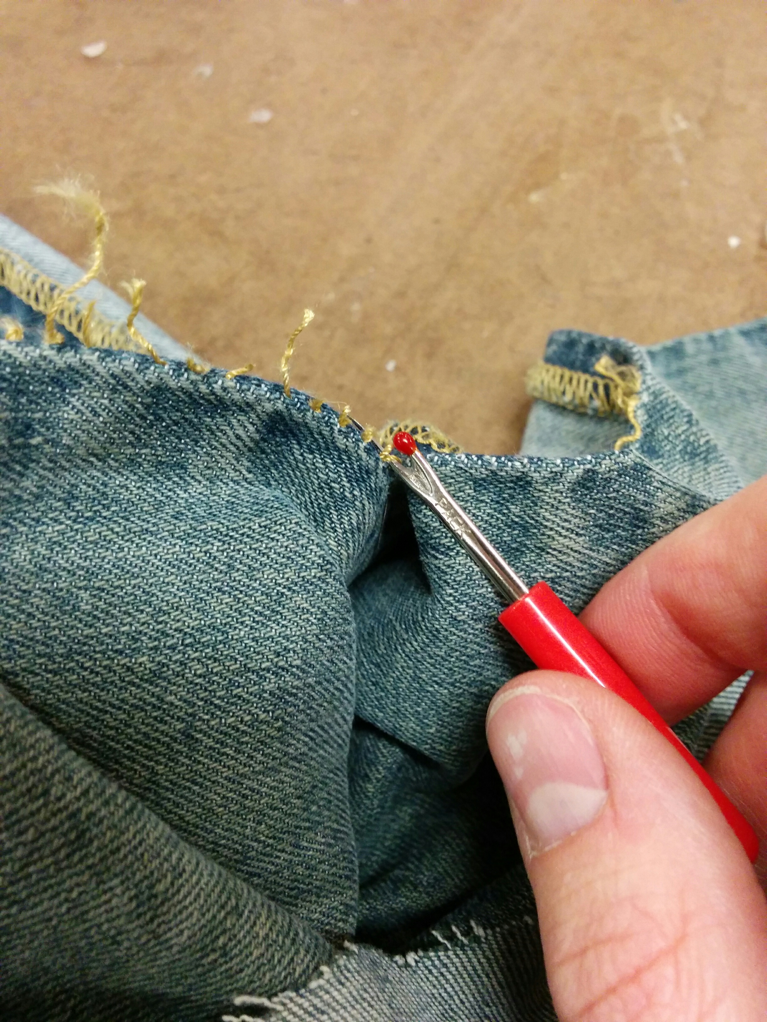
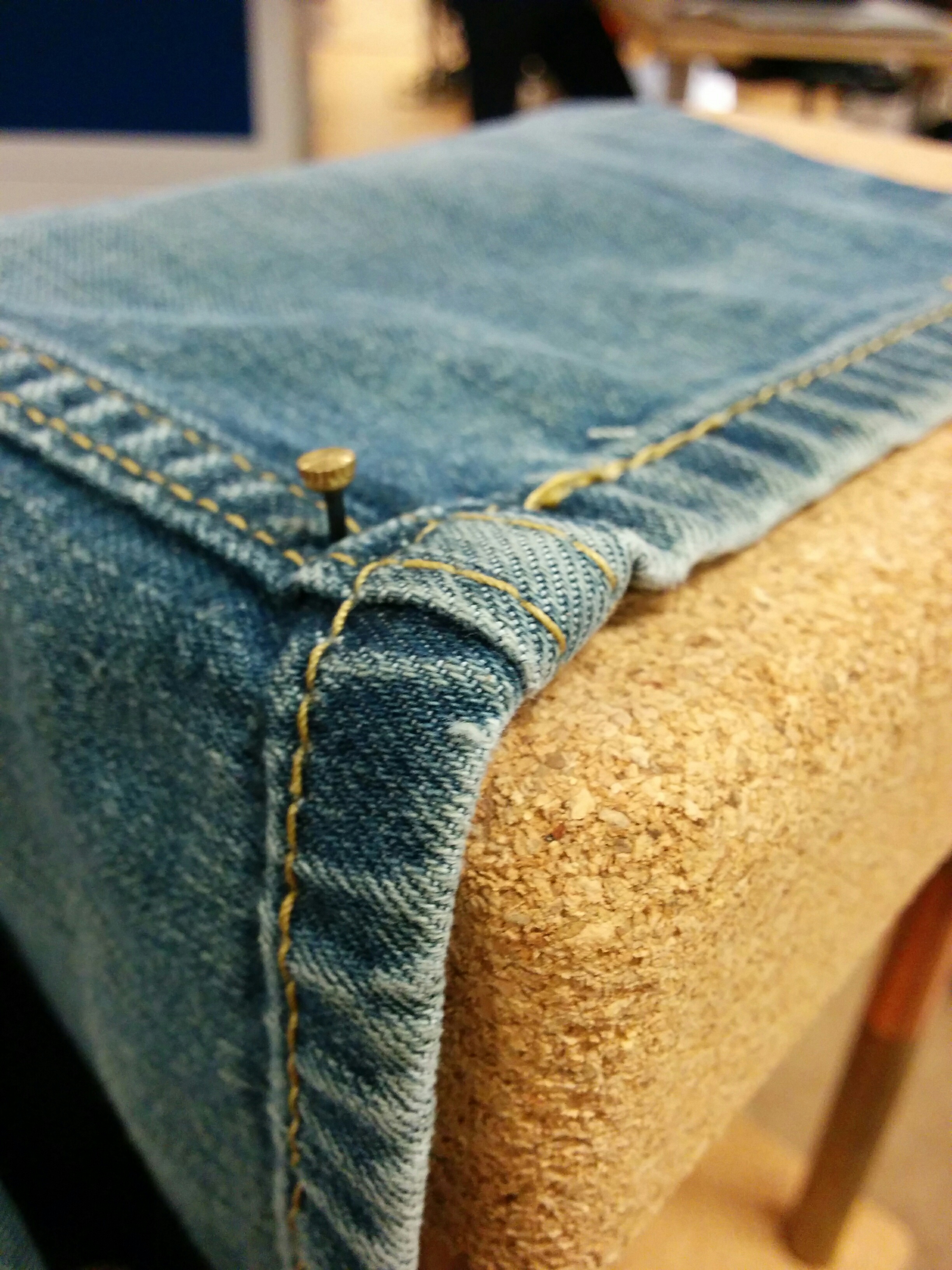
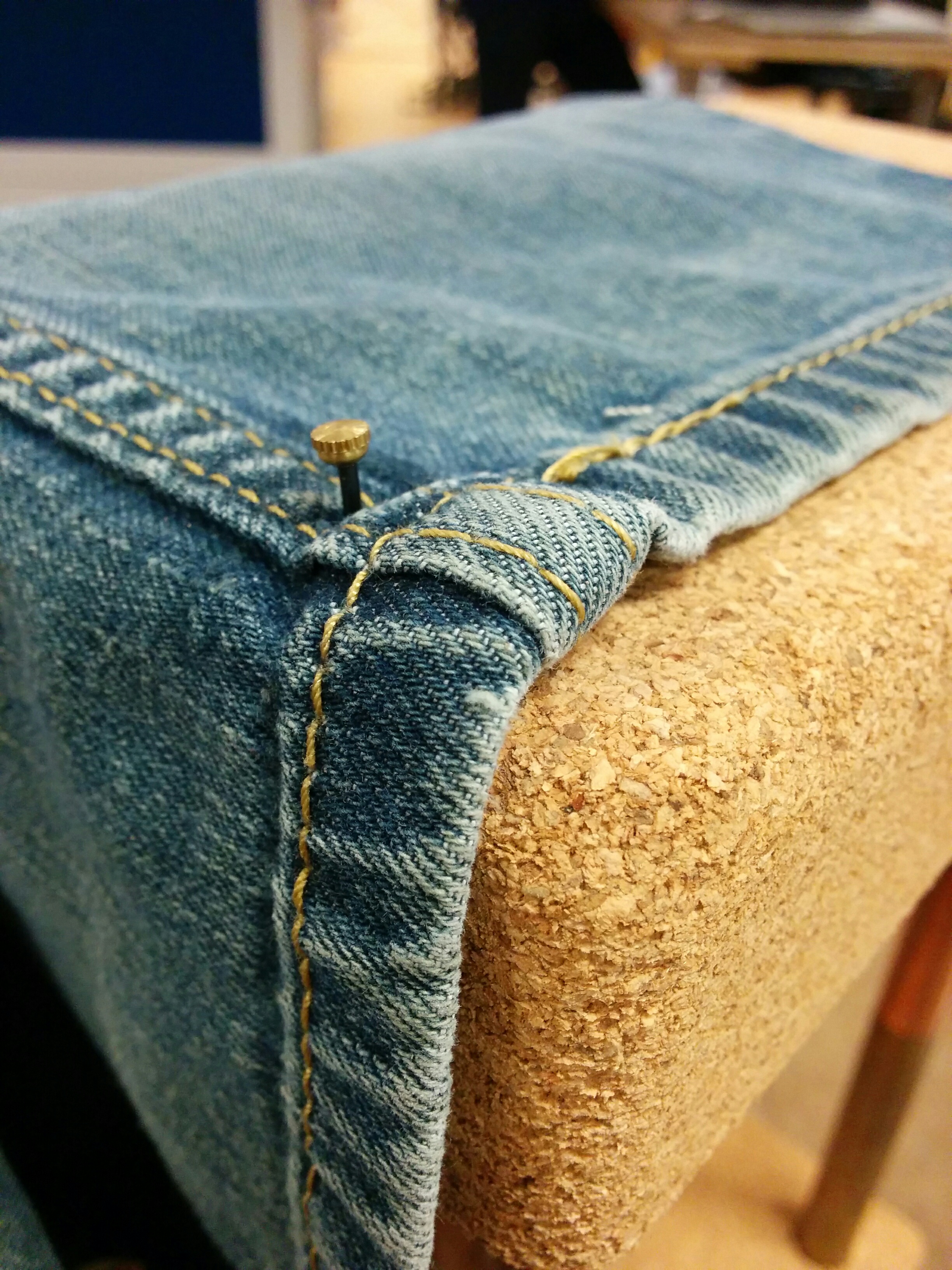
But in order to give it a somewhat more finished look, I used the denim I had to create a soft type of mallet head. This is temporarily secured with a rubber band. I imagine in the future being able to wrap different materials around the ball in order to create different sound qualities.

The first arm length seemed to be a little too long, so took out the wire and shortened it.

Better, but not quite cutting it.

Starting to get a good effect, but running out of room.

I think I’m going to continue experimenting with different tips. The speed of the motor on it’s own seems so powerful, but when you put any kind of load on it, it slows down dramatically. I’m thinking of perhaps doing a simple rubber coating of the tip to make it as light as possible without leaving a sharp edge. There are a few other avenues I could take, and I’m excited to come up with more ideas.

Intro to Fab 4: Materials and Fasteners

We have been pushed away from acrylic and plywood and towards… well, anything else! This week’s assignment is materials and fasteners. Exploring the broader world of materials and their benefits (and drawbacks) is important. And knowing how to attach them together wouldn’t be bad, either. But I was also really happy to see Ben’s emphasis on how fasteners can be emphasized rather than hidden. Sometimes you want to “celebrate the fastener”. Really inspired by this assignment.

img_20161201_182541

I wanted to work with cork. Cork boards are one of my design go-to’s for personal spaces, as it allows me to attach and remove things at will. I like that re-usable and flexible aspect of being able to stick things into cork. Being able to change what is on my wall quickly, trying something out but take it down if I want without damaging a wall, it is great. That might be justifying my commitment issues, but that is the topic for a different blog post.

And despite it’s re-useability, it doesn’t (have to) look cheap. The raw texture of it appeals to me, and the cork I got was a yoga block from REI so it looked better than some of the flat cork board material I have gotten from Staples in the past.

I wanted to use brass elements, as I haven’t really done much with metal yet. At the hardware store I got the last four of 5/8″ pieces of brass plumping pipes, and some decorative fasteners I thought might match.


img_20161201_182859img_20161201_182903

I wanted to see how soft the cork was to work with. It was light, but felt dense at the same time. Pressing one of the brass pipes into it, with a decent amount of force, left a mark. If I really pushed or used a hammer, I could probably force it into the cork.

img_20161201_183841

But I wasn’t going to take that approach. The 5/8″ spade drill bit was perfectly just smaller than the tube, which I wanted to mount into the cork. The sizing made me optimistic for a friction fit.

img_20161201_185800 img_20161201_190013 img_20161201_190150 img_20161201_190334 img_20161201_190344

With some generous advice from the shop staff (again! I’m growing to love them), I setup the cork block to be cut down the middle. We weren’t sure what to expect, but it cut like butter. Very minimal amount of dust, and you would barely be able to tell that it was cut at all from a distance if they were held together. And then they smoothly rub together with no friction. They were fun to just kind of touch and play around with like a toy. I’m looking for excuses to use cork in the future because it is so fun to cut in this way.

img_20161201_190433 img_20161201_190725 img_20161201_193128 img_20161201_193321 img_20161201_193443 img_20161201_193529

I figured out where I wanted to mount my pipes, marked both pieces appropriately, and setup the drill press. I figured out how much depth I wanted to achieve, and made a placement jig so that I could quickly drill the holes in a consistent manner. Coring out the cork was easy, but very messy. LOTS of cork dust. I tested the pipe, and at first was afraid the hole might be a little *too* small. But that turned out to be perfect. Great enough for a friction fit, but I could pull it back out if I needed.

img_20161201_194901 img_20161201_195029 img_20161201_195727 img_20161201_200306 img_20161201_201628

Grrrrrr! The stickers on the pipes could not be any stickier or harder to peel off. Once I finally did get them off by using the shop sink, there was still adhesive on the surface. I took some isopropyl alcohol and rubbed the gunk off of them, which took longer than I thought.

img_20161201_201638 img_20161201_202109 img_20161201_202117

Fasteners. I had gotten little golden colored hooks that had threaded screws as their base. Marking out the middle of one of the cork pieces, I put the hook in the center of it.

img_20161201_202131 img_20161201_202143 img_20161201_202155

After that, I hung the metal carabiner/key holder on the hook. That this point, I thought that I had something compelling looking. I have consciously not told you what I was making up until this point, because I wasn’t entirely sure what it was that I had in my head when I started. I’m imagining many potential uses for this basic form. Maybe hanging a small succulent to dangle in the middle, or a small light source. Or maybe it is just a really fancy key holder.

The real point of it is that you can tack things into it and change it’s appearance and functionality. With this in mind, I moved onto my next step and next material.img_20161201_202921 img_20161201_203209 img_20161201_204130

I had a pair of jeans that had been torn very badly at the knees and were only getting worse. I decided to gift myself a new pair of jean shorts and get some material for my homework at the same time. I used a seam ripper from the soft lab and flattened out both pieces.

img_20161201_204332 img_20161201_204337 img_20161201_204440 img_20161201_204443 img_20161201_204708 img_20161201_205721

I wasn’t sure which fastener I wanted to use to connect the denim to the cork. But thats ok, because its cork! I can always take them out and put in something else. I opted for the smaller nails, and left them a little elevated in order to make them more prominent and noticeable.

img_20161201_205727 img_20161201_210337 img_20161201_210316 img_20161201_210239

img_20161201_210212 img_20161201_210156

While I could push them in for the most part, at some points it was way more difficult so I used a mallet. I also decided I liked the inside of the denim better than the outside, so I undid everything and flipped it (thanks again, cork!).

img_20161201_210623 img_20161201_210640 img_20161201_210647 img_20161201_210726

I then hung a portable speaker in the middle. It can open up and hold a phone inside of it. This was one of my initial ideas, that I could kind of create a speaker enclosure that looks pretty by making something that wraps around a pre-existing speaker.

When first looking for materials, I had the “cork + warm metal” material palette going. But I was afraid it was going to get a little too steampunk-y. But again, the fact that you can stick anything into the cork helps with the potential versatility a lot. Yuèpíng was nice enough to let me borrow a couple of her pins to test out my customization theory.


img_20161201_212511 img_20161201_212521 img_20161201_212626 img_20161201_212639

Adding and removing the pins left minimal wear. I’m sure if this was used constantly, eventually the materials would look a little worse for wear. But for the time being, the use case worked. I’m happy with the end result… even if I’m not entirely sure what this thing is. It is sturdy enough to stand on it’s own and hold certain amounts of weight, but also temporary, flexible and re-useable. Really glad I got a chance to play with cork, and will be using it again in the future. Going to try and hunt down some affordable sources to stock up.

Intro to Fab: Enclosures

This week we were tasked with making enclosures. Since we’ve also been ramping up towards the end of Intro to Physical Computing, this assignment coincided with making some next-step proof of concept builds for my final project in that class.

I asked Ben for some advice, and was convinced to start out more basic. My initial instinct was to try and create a curved shaped enclosure right off the bat, but it makes more sense to start simple. Using a normal pre-made enclosure and then attaching it to a microphone clip seemed to be a good first step.

img_20161117_163225

I went to Tinkersphere and bought a project enclosure that complimented the size of my microphone clip, and then bought surface mount buttons for it. They were the rare kind that make no noise when you press them (if I am using this with a microphone, it is best to avoid clicky noises). With these two constraints, my choices were made fairly quickly for me. However, I wasn’t so sure about the spacing:
img_20161117_163505 img_20161117_163615img_20161118_142300 img_20161118_142336

While perhaps technically possible to fit all the buttons onto the surface, I started having second thoughts when I brought everything back to the shop and was able to measure. Luckily, Ben had given me a different enclosure to try out. The more I looked at it the more it made sense:

img_20161118_150907img_20161118_143902

“Small is hard” kept echoing in my head, and even though larger I felt like this could work decently for my play testing. I went to measure out the distance between buttons and started making some holes on the drill press.

img_20161118_143530 img_20161118_143711 img_20161118_144138 img_20161118_145826 img_20161118_150809

The box had two hinges made of plastic, one broken. Trying to clamp it effectively weren’t going well, and the one good hinge was looking a little flimsy so I just separated the pieces. Made for a much more secure clamp. Also, as you can see from my notes, I could only find a 1/2″ bit in the shop, and nothing larger. Would have to do for now, as John explained that the larger spade bits we have in the shop shouldn’t be used on plastic.

img_20161118_151948 img_20161118_151955

The holes came out alright, but I was hoping that maybe I could just kind of force the buttons in. The plastic turned out to be much more resilient than to allow that. So I cleaned out the inside pieces of the enclosure and started slowly, piece by piece, expanding one of the holes with the Dremel.

img_20161118_152729 img_20161118_152139img_20161118_153033img_20161118_153047img_20161118_153208

It was more Dremeling than I thought I would have to do. You can pretty clearly see the hole size difference with the naked eye. It wasn’t too bad, but if I was making multiples this is where I would be kicking myself and/or going on a quest for the perfect bit.

img_20161118_155125

Which is even more apparent when you look at the end result. After trying to keep an even hand, slowly testing the button and returning to the Dremel, then sanding out the end results, some of the holes were looking… interesting.

img_20161118_160001 img_20161118_160005 img_20161118_170112 img_20161118_170129

However ugly, they were effective. Constantly testing them made sure that the buttons fit as tightly as possible.img_20161118_170230 img_20161118_170315

Putting this up against the mic clip, I was happy that I started walking before I ran. Going with a more straightforward box now feels like a wiser choice when considering how things can and will change over my prototyping process. But I wasn’t sure of the best way to properly attach them together. Because of the nature of the clip, which expands as mics are inserted and is tightly flush against the surface of the mic neck, there were many approaches that I would normally take that were off the table.

Not entirely sure where to turn… I went with plain ol’ hot glue.

img_20161118_171806 img_20161118_172337 img_20161118_172917

Hot glue. It’s like this totally normal thing that people use all the time, right? Wow can it get messy quick. One day I would like to get some tutoring on elegant hot glue technique (if such a thing exists). Luckily, it was easy enough to pull away the fine strands and peel off the egregious errors where necessary. I wound up with somewhat of a loose hinge:

img_20161118_173014img_20161118_173136

Then with that I was able to do a second round that covered more surface area and adhered solidly.

img_20161118_173422img_20161118_173757img_20161118_173844

Yeesh! These glue strands get everywhere. But after some cleaning up I wound up with something fairly sturdy:

img_20161118_173555 img_20161118_173610 img_20161118_173619

That is where I’ve left off for now. I have some parts coming in, and depending on specifics might change the focus of the rest of this assignment. It could make sense to just keep it more or less looking the way it is and hook it up to my microcontroller once I get all the parts, and keep this as a version 1.0 functional prototype. However, despite it’s early 80’s beige/gray charm, there is a part of me that would like to make this look a bit more presentable. Updates will soon follow.

Part 2

Having some issues uploading my images, but I will do so as soon as my internet connection gets a little better. In the meantime, I have added a little slot for my microcontroller to sit inside of the enclosure. There were some other issues, but I’ve got some decent end results to share. More updates tonight and tomorrow!

The first dissapointment I had upon returning to my project was that the hot glue did not hold. Not sure if this was due to being bumped (it was in my open project box), or otherwise.

img_20161122_131716

But it was an opportunity to make the work a little easier to handle. I received the microcrontroller I need for my Physical Computing class, the Teensy LC.

img_20161122_141502

But there are no mounting holes on the board! I hadn’t accounted for this when I originally ordered, but it removed the option of using standoffs as a mounting solution.

img_20161122_132226 img_20161122_132452

I started clearing out space in the enclosure in order to hold a bread board, which fit *just* perfectly…

img_20161122_134450img_20161122_134415

Until I put the board onto the bread board and saw I didn’t have enough clearance. The last button was getting in the way.

img_20161122_141521

I started playing around with placing the board onto the plastic nibs that were inside of the enclosure to start.img_20161122_141808 img_20161122_142023 img_20161122_142309 img_20161122_143129img_20161122_145648 img_20161122_150719

It isn’t very pretty right now, but I think for my initial functional play testing this can serve its purpose. Next step was to re-glue and attach a cable.

img_20161122_151515img_20161122_151935 img_20161122_152229 img_20161122_152236 img_20161122_152317

Once I had gone all in on my enclosure choice, it made it a little difficult to go back. But I think after this assignment I’m definitely going to re-asses my options. For my playtesting, I might wind up kind of hacking this thing apart into something resembling less of a traditional enclosure for the sake of being able to re-wire and re-position things quickly. But I certainly learned plenty about what was possible in terms of pre-made enclosures and will feel comfortable about going to the drill press to quickly produce little homes for my projects.

Intro to Fab 3: Laser Cutting

“Don’t fall in love with the laser! DON’T fall in love with the laser!” While I will never forget Ben’s words, I will say that at the very least I had a great weekend with the laser and I will be calling it back.

Having never used acrylic before, I was curious about making something that could accentuate the shiny, slick qualities of it. I had some EL wire around that I hadn’t gotten to use yet, and came up with a lighting idea. An acrylic cut shape with multiple holes in it that I could weave the EL wire in and out of. The wire seemed sturdy enough to hold itself and light amounts of weight, so I got excited enough about the idea to see how it would actually work.

screenshot_ai

I was really happy with my trip to Canal Plastics. They were a great help, there were a bunch of 24″x12″ precut sheets of laserable acrylic that fit our bed dimensions perfectly, and they offer student discounts of 10%.


I was advised by people in the shop to keep the paper on the acrylic while laser cutting, and given some friendly advice about speed, power, and frequency. I started cutting at 50/100/100.

img_20161112_141322

I ran it twice just to be safe.

img_20161112_141545

But it wasn’t budging, and the tape trick of trying to pick up cut pieces was not working at all. After further discussion, I dropped the speed to 30.

img_20161112_142042

A few flareups on the surface convinced me thoroughly why the fan needs to be on. However, after two extra times on 30/100/100… still not budging…

Take advice, but cautiously. And double check everything. After 4 laser sessions, I went to the source and checked the cutting guide on the ITP website. Suggested speed? 15. Change the settings and here we go.

img_20161112_144049

Woo! Really glad for that fan now. But it was working. The pieces were starting to fall on their own.
img_20161112_144158img_20161112_144618

And the tape trick was working like a charm. I moved everything to a table and started popping out the little pieces. Using my hands was fun, like popping bubble wrap. But towards the lower right side I needed to use a screw driver for a little extra help.img_20161112_144913 img_20161112_145023 img_20161112_145027 img_20161112_145213img_20161112_145651img_20161112_150116

And then I started removing the tape

img_20161112_150554 img_20161112_150750 img_20161112_151126

I think that, in the end, I am happy I kept the tape on. Being able to see the laser cuts (or lack there of) was a real help when I was having trouble. However, it was a bit finnicky cleanly taking all of it off when there were so many intricate cuts. Worth keeping in mind for future jobs.

Next up was the EL wire.

img_20161112_151653 img_20161112_154354

I think there should be honest subtitles for classes at ITP. This should be, “Intro to Fabrication: Why did I think that one part would be easy?” Feeling like I was done, I started “just” threading the EL wire through the holes in my desired pattern. Getting to know the right amount of flex and force, trying to keep things straight, double checking my work, all while trying to be gentle with everything was more difficult than I thought it would be. Essentially, I’m trying to do a kind of EL wire cross stitching. It is possible, but just for the record, not nearly as quick as with needle, thread, and cloth.

But in the end the idea works, perhaps with some managed expectations. I think I might try to iterate a bit on this to help manage the wire more, but I like the effect overall in a dark room.

img_20161112_161441 img_20161112_161501img_20161112_161514img_20161112_161538img_20161112_161559

Intro to Fab 2: The Multiples

Our task for this week in intro to fabrication was to make multiples of a design (at least 5). I have had an idea for what I’ve called a “percussive wand”, a tool that allows a DC motor and attachments to be used as a musical instrument. At first I thought about the multiples challenge in terms of something that would fit as a set of things. However, it occurred to me that if I wanted to do user testing of a prototype, it might be good to have multiple prototypes to give out.img_20161108_072635

img_20161108_072610
Credit Joe Mango for help thinking about how to screw in the handle


Starting Material

I went to Midcity Lumber and picked up 8ft of 2×4 pine. I figured that each wand would be approximately 1ft long, so to acheive 5 solid pieces I bought more than I needed.

img_20161104_151211img_20161104_151220


Process

Midcity does $2 a cut. For the sake of my fellow MTA riders, I had the 8ft cut into two pieces. When I returned to ITP, I started measuring initial cuts. From 4ft to 1 ft pieces.

img_20161104_151908

But the Midcity cuts weren’t perfect. I had initially thought I would be clever and use the mitre saw to cut both pieces at the same time. However, after marking the middle point of both pieces, I realized that they weren’t *exactly* the same length. It wasn’t that much more work to individually cut each piece, so I opted for that.

img_20161104_152511

A little improvisation when I needed a straight edge to draw the cut…

img_20161104_153020img_20161104_153119img_20161104_153218

Will definitely need to sand these! I knew cuts were rough, but I was surprised at the amount of splintering.

img_20161104_154453


Moving onto the 45 degree cuts. This creates the handle for each wand, allowing a sloped end that meets up with the handle. Additionally, it saves material.

img_20161104_161651 img_20161104_161759 img_20161104_162016

Weird… didn’t notice those little dots before. Wait! I forgot a shim when clamping!img_20161104_162203


Measuring out positioning the mitre saw, when I realized… “Hey… this top one moves!”

img_20161104_162329


I cut 8 pieces and hit my first Bad Pancake™ ! When sawing into one of the pieces, it seems like I hit or dislodged a gnarly knot inside of the 2×4.

img_20161104_162453

I had my first pieces, and then did an initial sanding.
img_20161104_164529 img_20161104_170015 img_20161104_170040img_20161104_170111img_20161104_170122


Can I save a pancake? I used some wood glue and clamps to see if it could be salvaged. Had to go with the speed clamp because the heavier clamps kept tipping everything over.

img_20161105_141259 img_20161105_143259

Did it work? Not like this! I waited 30 minutes as directed and the piece came apart pretty easily. I proceeded to totally over compensate, making a bit of a glue-y mess in the process. I waited longer for the clamping and managed to save the pancake! Maybe not the best choice for final production, but perhaps useful in my jig process later.

img_20161105_144348img_20161105_144847img_20161105_165313


Making a jig

I was trying to find a good way to position my pieces and keep them stable as I did my first drilling. This is where you can really see that each piece is certainly not “exactly” the same. This ain’t photoshop! No copy and paste here.

img_20161105_171436img_20161105_172421

img_20161105_172653

This made designing a good jig a little tough. I needed a tight fit, but thats hard to do when things aren’t exactly the same. Had to mess with it a bit… and then it failed on me. Turns out I wasn’t putting enough screws in it, and it started moving on it’s own. Not helpful, jig. I decided to re-think my approach.img_20161105_173049img_20161105_173419


Back to the drawing board. I never lost faith in you, bad pancake. Your second life in service to the jig will never be forgotten.

img_20161105_174316 img_20161105_174412 img_20161105_180236


The first (full) pancake

Before duplicating my process, I wanted to test it. I used one small drill bit as a pilot hole, then used a 1/4″ drill bit to just hit the top and allow for a screw head. Then I screwed that, moved the handle, applied glue between the handle and the body, and then did my drill and screw routine on the other side. Then clamp as the glue dried. (And slowly learning my lesson about using too much glue.)


img_20161105_181727 img_20161105_182040 img_20161105_182056img_20161105_181654


Assembly line

At the end I had a decent piece that felt sturdy in the hand. Then I started prepping everything for the assembly line. Marking out drill spots, arranging my clamps and double checking the workflow.

img_20161105_182817 img_20161105_185001 img_20161105_185410 img_20161105_185840 img_20161105_192105 img_20161105_193040


Stain?

I brief intermission followed as I had to go home for the day. I took a piece of wood with me and tested some stain that I bought, since we aren’t allowed to use stain in the shop. After an overnight drying, it was interesting to see the results. I kind of liked the color, but I feel like it would do well with a waxing. Ultimately, with some other issues outstanding (more on this later), I decided to go against staining. If I needed to make changes and alterations, it would just mess up my stain job, I’d need to re-apply, and make things even more messy and complicated. Interested in using it in the future, though.

img_20161106_135840 img_20161106_135851 img_20161106_135902


Glue n’ Screw

With that tangent aside, I set up the workflow for the rest of the pieces. Going to the shop when no one is there is *very* useful, as you can take as many drills as you want. I laid them out in order: pilot drill, space drill, glue, screw.

img_20161106_172455img_20161106_172023 img_20161106_172212 img_20161106_172342img_20161106_172733img_20161106_172834img_20161106_172906


I even made a little makeshift shelf for my small clamp so it would be elevated and within arms reach.

img_20161106_174654


Then I used cardboard to protect all the pieces and clamped them up for a while.

img_20161106_181253 img_20161106_181324


Sand again

I can almost hear Ben’s laughter now. None of these were “exactly” the same at all. Handles weren’t perfectly lined up, and gaps between the handles and the wand were visible and varied from piece to piece. This didn’t interfere with the base function, however. I decided to sand them down to make them as flat and uniform as possible, and additionally soften sharp edges that would be gripped by hands.

img_20161106_200621


The heartbreak

damagedpackage

Why Amazon? Why? Whyyyyyyyy? One of my sets of components had been damaged in transit and was being re-sent… for delivery on Wednesday. Additionally, there were some issues with delivery of the other pieces. I now know more about the ITP, NYU and USPS mail system than any sane person needs to. But I was sweating a bit as well. This is what I was keeping in mind when I didn’t stain: if I had to change things around, I might need to make more cuts or change the design in order to get something done by Tuesday.


Time to improvise

As of this writing, I am waiting on a few other pieces of gear. Depending on when I get what I get, I’ll need to adjust my final project. Will I get my materials on time? Will I have to radically change my final design? Will Ana up front ever forgive me for pestering her incessantly about when packages are getting in? Find out next time in part two of… The Multiples!

img_20161108_101138
(During the intermission, I will solder the components that I *do* have)

Thank your shop staff: Dhruv

I have been blessed by the friendly shop staff! Dhruv helped me figure out an alternative mounting solution that would replace my broken/missing delivery.img_20161108_111954

Essentially, we found a threaded bolt that was the perfect size for the clips that I have. Dhruv helped me get the right drill bit, and I went at testing the theory.img_20161108_110635img_20161108_111150

Yes! After the proof of concept, I was ready to continue. First marking, then drilling, and of course going back to the sander yet once again.img_20161108_120927 img_20161108_121900 img_20161108_122142 img_20161108_123119


I found the right tool for the job (ratchet, and then wrench for more delicate scenarios). Then, I laid out everything again to do my assembly line round 2.

img_20161108_123737 img_20161108_124416

Not without a brief heart attack thinking that I had permanently attached a ratchet head to one of my pieces. (It was really… really stuck on there.)

img_20161108_124937


And I got it working! Except…♫one of these things is not like the other, one of these things does not belong♫img_20161108_130514

(Yes, it annoyed me enough that I fixed it. Luckily my design made it simple to unscrew and re-screw everything back together the right way).

As of this writing, I had gotten this far but still hadn’t received my packages yet. Desperate, defeated, and considering an expensive run to Tinkersphere. But just when I was getting ready to give up, I received a call… from the Campus Mail Services!

I’m not sure I will be able to post everything completed before 6pm tonight, so I wanted to get this blogged least to show how much I have gotten so far. I’m confident I will finish tonight and have something to show tomorrow morning. Updates to follow, stay tuned!

And now, for the thrilling conclusion of… The Multiples!

Motors! Battery cases! And just when I thought it couldn’t get any better, Ana hand delivered my batteries to the shop. Lets get these guys on!

img_20161108_185415

Of course, it would have been better to not have the screws in. But instead of undoing and redoing those, I found some wood scraps to elevate as I cut.

img_20161108_190100

img_20161108_190104 img_20161108_190147


With my first test set, I was ready to duplicate.

img_20161108_190403 img_20161108_190558 img_20161108_192049 img_20161108_192332

Lots and lots of soldering for the wiring

img_20161108_200159


The final product(s)

img_20161108_203457 img_20161108_203725 img_20161108_214822 img_20161108_215008 img_20161108_215018 img_20161108_215039 img_20161108_215103 img_20161108_215113 img_20161108_215121 img_20161108_220621


I had some material I was trying to attach to the motor in order for it to hold different percussive mediums (brush, wire, etc). However, that did not work out that well. I think I’m going to set these aside for now and perhaps take more time in approaching that specific feature in more detail later.

*Phew!* I got something to show tomorrow. Certainly learned a lot. Can’t wait to discuss more and see what the rest of the class has cooked up.

And that concludes the thrilling tale of The Multiples!


Intro to Fab: Week 1

Excited to go into a new class for the second half of the semester! Ben started off Intro to Fabrication with a really wonderful story about a flashlight he made for his grandmother when he was a child. Our first assignment was to build a flashlight of our own. The definitions have been generously outlined as something 1) portable, that 2) creates light.

Inspiration

I like the idea of things that are dual use, to save on resources, space and money. Maybe not the best example, but I’ve always been drawn to the glowing umbrellas in Blade Runner. A light and an umbrella in one! (Not sure how often that is needed, though…)

As for this assignment, I thought it would be nice to create a flashlight that wouldn’t only sit in a drawer for most of it’s life. A more practical approach would be something like a lantern. It can be portable light when you need it, but can also sit stationary as a lamp.

A simple paper lantern

Drawings

Maybe there could be a specially shaped lamp that could have the functionality of a flashlight when desired. A lamp type use case when needed, and directed light when desired.

img_20161031_093955

What I came up with was essentially a “standing” flashlight. Hold it like a normal flashlight in one use case, but when you place it light-down there are affordances to let certain amounts of light through.

Raw Material

I enjoy having clever ideas, but I am skeptical of “clever” ideas. What if there is a good reason I haven’t seen this kind of design somewhere? I thought the best initial incarnation of this concept would be cardboard. Test out if the general form is even a good idea to begin with.

img_20161029_143156

The cardboard is brought together by duct tape. The inside of the piece has tin foil on the sides to increase reflectivity, which is held into place by duct tape and normal clear tape. There is also  a little patch of velcro for functionality I will outline later. At one point I used to styrofoam to test out some functionality, but it did not stay in the final design.

The light source is a breadboard with 4 yellow LEDs, appropriate resistors, a 9 volt battery source with appropriate connection terminal, and a “soft touch” switch. These are connected via stiff, on-board jumper wires, a looser jumper cable for the switch, a screw terminal to connect the switch to the wires. I used some alligator clips during testing of the circuit, but they did not stay in the final design.

Mid-Process

The questions started almost immediately, as I was unsure what would be a good size for the frame. I wanted something small enough so that I could hold it in my hand but large enough to justify as a stationary light source. I wound up going with 4.5 inches.

img_20161029_143736 img_20161029_143935

I wired up my breadboard with 4 LEDs and a 9 volt battery and shone the light through my cardboard tunnel. Not too bad.

img_20161029_152545 img_20161029_152602 img_20161029_152643

Then the tin foil was added to increase light reflection. Not really sure this made that much more of a difference. To my eye, it was more than these photos might convey, but certainly a minimal difference. However, the light was coming out and was forced into a direction, so I decided there was enough functionality for now.

img_20161029_152946 img_20161029_152956

Cuts were added to the bottom 3rd of the cardboard to create the lamp legs, and measurements were made in order to cut a piece of styrofoam. This was a quick way to punch out a hole and rest my light on top of the structure to see how the lamp functionality worked.

img_20161029_154050 img_20161029_154507img_20161029_155649img_20161029_160012img_20161029_160213

Getting there. But the legs need to allow more light out. I measured and drew my window holes, and cut with my box cutter. Not without some issues…

img_20161029_162055 img_20161029_163157

But eventually they were all clear. This was the moment of truth: would the legs hold the weight of the entire light source?

img_20161029_164157

It stayed up! Also, this gave me a moment to turn off the lights and test the LEDs. Glad I went with the yellow, which provide a much warmer glow.

img_20161029_163725

The switch was tested with alligator clips, then made more permanent with male to female jumper wire, a block terminal, and the soft touch switch. I cut another piece of cardboard to make a more permanent top, and attached the breadboard to it via a patch of velcro.

img_20161030_163250

img_20161030_165725

img_20161030_164733

A cross pattern cut was made, which allowed me to push the push button base through while keeping as much tension as possible to hold the button in place.

img_20161030_171029 img_20161030_171312

Then I taped one side of this ‘lid’ to the top of the structure. Instead of taping the entire piece down, I created a kind of flap out of duct tape on the other side. This attaches to the side of the light with velcro. This allows access to the inside, for electrical troubleshooting, replacing batteries, or adding/removing LEDs.

img_20161030_172033 img_20161030_172041 img_20161030_172219 img_20161030_172247

List of tools used

The star tool of the show was a box cutter for going through cardboard and styrofoam. Pencil and measuring tape for marking things out, along with a hard ruler for marking as well as being a hard object to bend cardboard around in straight lines. A very small flat head screwdriver was used to secure the block terminals that held the wiring. Alligator clips were used for the testing of the circuit.

img_20161031_113639

Final Images

Despite its cardboard prototype appearance, I’m happy with the result. The variations on this concept are many; differing sizes, leg/body ratios, and patterns for letting light through. Getting something together, even if only in cardboard, gives a good opportunity to really feel what design choices can resonate the most.

img_20161031_120435 img_20161031_121044 img_20161031_121158 img_20161031_121219 img_20161031_121327